B94SDGOB1392802.11bgn 1x1 SDIO Module
HP Inc.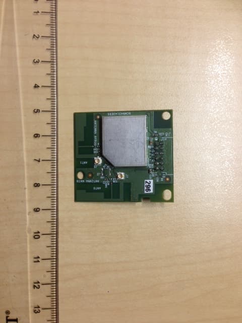
Click to zoom
Application Details
- Equipment Class
- DTS - Digital Transmission System
- Date of Grant
- Sep 19, 2013
- Application Purpose
- Original Equipment
- Date of Application
- Sep 19, 2013
- Equipment Note
- 802.11bgn 1x1 SDIO Module
- Frequency Range
- 2412.00000000 - 2462.00000000
- Company
- HP Inc.
- Country
- United States
Documents & Files
Document Text
Text extracted from the exhibit documents filed with the FCC. Open a document above to read the original.
Users Manual
Introduction: 802.11b/g/n WLAN Module, SDGOB-1392 User's Guide Before you begin Things you should know SDGOB-1392 network Before you begin Obtain the following information from your network administrator (if you are a home user, obtain this information from the person that installed your wireless access point): l Network names (SSID) of the specific wireless networks that you want to connect to. l WEP (Wired Equivalent Privacy) key information (if any) for the networks you want to connect to. l For Microsoft® Windows® networking, your customer name and workgroup name. l For your network account, your user name and password. l Your IP address (if not using a DHCP server) Things you should know When you start your computer, your SDGOB-1392 card detects certain wireless networks that are within range. Before you can connect to these and other wireless networks, you must configure a profile for each network using the information you obtained from your network administrator. WEP is a security protocol for wireless local area networks (defined in the IEEE 802.11g standard) that encrypts data sent over radio waves. The use of the WEP key is optional and can be enabled or disabled. If the network you are connecting to has enabled WEP, you must also enable WEP in the network profile and set the WEP key to match the WEP key used by the network. Otherwise, you cannot connect to the network. Broadcom SDGOB-1392 network The SDGOB-1392 card solution allows you to make a wireless connection to a network, as illustrated below. Back to top Using the Broadcom Wireless Utility: Broadcom AirForce™ 54g™ and Intensi-fi™ Wireless Network Adapter User Guide Back to Contents Page Using the Broadcom Wireless Utility: Broadcom AirForce™ 54g™ and Intensi-fi™ Wireless Network Adapter User Guide Overview Utility Components Overview The Broadcom Wireless Utility enables you to do the following network tasks: l Manage your wireless networks and create network connection profiles (Wireless Networks tab) l Connect to available networks (utility icon in notification area) l Get information about the network status and signal and noise of your network connection (Link Status tab) l View current and accumulated statistics (Statistics tab) l Find out which broadcasting networks are in range and search for nonbroadcasting networks (Site Monitor tab) l Run tests on the wireless network adapter (Diagnostics tab) l Get date and version information about the utility, and software, hardware, and location details about your wireless network adapter ( Information tab) l Manually add or delete trusted servers and enable the manual acceptance or rejection of auto- provisioning and A-ID group changes ( Wireless Networks tab) l Manually import EAP-FAST PACs (Wireless Networks tab) In the utility, you can open Wireless Network Wizard to connect to a basic network or create an ad hoc network, or you can open the Wireless Network Connection Settings tool to connect to an advanced network. To do any of the other tasks, click the tab that is associated with the described task. To start using the utility, right-click the utility icon in the notification area, and then click Open Utility. If the icon is not available, open Broadcom Wireless Utility in Control Panel. NOTE: The utility icon may not appear exactly as shown here. See " Table 1. Signal Strength Indicated by the Broadcom Wireless Utility Icon." Utility Components Utility components include the utility icon in the notification area, the six utility tabs, and Wireless Network Connection Settings. file:///P|/User%20Manuals/WLANCard-UM302_LaLa/HTML/utility.htm (1 of 12)4/25/2006 1:57:41 PM Using the Broadcom Wireless Utility: Broadcom AirForce™ 54g™ and Intensi-fi™ Wireless Network Adapter User Guide Utility Icon To do any of the following tasks or operations, right-click the utility icon, and then click the appropriate item. l Open the on-line Broadcom AirForce™ 54g™ and Intensi-fi™ Wireless Network Adapter User Guide (Help Files) l Open About WLAN Card Utility to view links to Broadcom and Broadcom Customer Support websites and to view the version and date of the utility (About) l Hide the utility icon (Hide Tray Icon) l Disable or enable the radio (Disable/Enable Radio) l Connect to any of the networks for which you have created a connection profile and are within range (Connect To) l Open the utility to the Wireless Networks tab (Open Utility) l Open the utility to the Link Status tab to view information about the connection (Status) l Display a log of your wireless network events (Display Log) Wireless Networks Tab The Wireless Networks tab has tools that enable you to do the following: l Use the utility to manage your wireless networks l Add a network connection profile l Edit or remove a network connection profile l Change the order in which profiles are listed under Preferred network connections l Connect to any listed network without changing its order in the list l Disable or enable the radio (Disable/Enable Radio) l Show or hide the utility icon in the notification area l Choose which type of network to access l Lock or unlock a preferred network connection profile l Save your wireless network connection profiles as a WPN file l Import a WPN file l Manually add or delete trusted servers and enable the manual acceptance or rejection of auto- provisioning and A-ID group changes l Manually import EAP-FAST PACS On the Add menu, you can use either the wireless network wizard that is available from Broadcom Wireless Utility (see Connecting to a Basic Network or Creating an Ad Hoc Network Using the Wireless Network Wizard") or the utility (see "Connecting to an Advanced Network Using the Broadcom Wireless Utility") to add a network connection profile. To use the utility to manage your wireless networks, select the Let this tool manage your wireless networks check box. To add a network connection profile, click the Add arrow, and then click either Use Wizard (basic network) or Use Ut…
Text truncated - open the document above for the full version.
Users Manual
OEM Installation Guidance Document For HP SDGOB-1392 FCC ID: B94SDGOB1392; IC: 466D-SDGOB1392 Page 1 of 8 Conditions on using HP regulatory approvals: A. Customer must ensure that its product (the “CUSTOMER Product”) is electrically identical to Broadcom’s reference designs. Customer acknowledges that any modifications to Broadcom’s reference designs may invalidate regulatory approvals in relation to the CUSTOMER Product, or may necessitate notifications to the relevant regulatory authorities. B. Customer is responsible for ensuring that antennas used with the product are of the same type, with same or lower gains as approved and providing antenna reports to Broadcom. C. Customer is responsible for regression testing to accommodate changes to Broadcom’s reference designs, new antennas, and portable RF exposure safety testing/approvals. D. Appropriate labels must be affixed to the CUSTOMER Product that comply with applicable regulations in all respects. E. The Broadcom radio is approved as a client/slave device; to ensure compliance with local regulations, the device should be set to the country domain in which the access point is installed. F. A user’s manual or instruction manual must be included with the customer product that contains the text as required by applicable law. Without limitation of the foregoing, an example (for illustration purposes only) of possible text to include is set forth below: 1. USA—Federal Communications Commission (FCC) FCC COMPLIANCE STATEMENT: This device complies with part 15 of the FCC Rules. Operation is subject to the following two conditions: (1) This device may not cause harmful interference, and (2) this device must accept any interference received, including interference that may cause undesired operation. INFORMATION TO USER: This equipment has been tested and found to comply with the limits for a Class B digital device, pursuant to Part 15 of FCC Rules. These limits are designed to provide reasonable protection against harmful interference in a residential installation. This equipment generates, uses, and can radiate radio frequency energy. If not installed and used in accordance with the instructions, it may cause harmful interference to radio communications. However, there is no guarantee that interference will not occur in a particular installation. If this equipment does cause harmful interference to radio or television reception, which can be determined by tuning the equipment off and on, the OEM Installation Guidance Document For HP SDGOB-1392 FCC ID: B94SDGOB1392; IC: 466D-SDGOB1392 Page 2 of 8 user is encouraged to try and correct the interference by one or more of the following measures: -Reorient or relocate the receiving antenna -Increase the distance between the equipment and the receiver. -Connect the equipment to outlet on a circuit different from that to which the receiver is connected. -Consult the dealer or an experienced radio/TV technician for help. Any changes or modifications not expressly approved by the party responsible for compliance could void the user’s authority to operate the equipment. System integrators must include the FCC ID on the end product. FCC Radio-Frequency Exposure & Approval Conditions: 1. Antennas must be installed in the display section of Netbook/notebook/laptop computer to provide at least 20 cm separation distance from the transmitting antenna to the body of user during normal operating condition. - For modular SAR approved devices, the antenna is mounted on lossless foam material for SAR testing. In order to use Broadcom modular approval, PC–OEMs must install antennas with non –conductive materials surrounding the antenna. 2. Transmitting antenna(s) can only be installed at the display section of computer. When this device is installed other than notebook computers, at least 20 cm separation distance shall be maintained between the transmitting antenna(s) to the body of user or nearby person. 3. The antenna(s) used for this transmitter must not be collocated or operating in conjunction with any other antenna or transmitter within a host device, except in accordance with FCC multi-transmitter product procedures. 4. Only those antennas with same type and lesser gain filed under this FCC ID number can be used with this device. 5. The regulatory label on the final system must include the statement: “Contains FCC ID: B94SDGOB1392 “or using electronic labeling method as documented in KDB 784748. 6. The final system integrator must ensure there is no instruction provided in the user manual or customer documentation indicating how to install or remove the transmitter module except such device has implemented two-ways authentication between module and the host system. 7. The final host manual shall include the following regulatory statement: This equipment has been tested and found to comply with the limits for a Class B digital device, pursuant to Part 15 of FCC Rules. These limits are designed to provide reasonable OEM Installation Guidance Document For HP SDGOB-1392 FCC ID: B94SDGOB1392; IC: 466D-SDGOB1392 Page 3 of 8 protection against harmful interference in a residential installation. This equipment generates, uses, and can radiate radio frequency energy. If not installed and used in accordance with the instructions, it may cause harmful interference to radio communications. However, there is no guarantee that interference will not occur in a particular installation. If this equipment does cause harmful interference to radio or television reception, which can be determined by tuning the equipment off and on, the user is encouraged to try and correct the interference by one or more of the following measures: -Reorient or relocate the receiving antenna -Increase the distance between the equipment and the receiver. -Connect the equipment to outlet on a circuit different from that to which the receiver is connected. -Consult the dealer or an experienced radio/TV technician for help. This device complies wit…
Text truncated - open the document above for the full version.
Attestation Statements
Inkjet Consumer Solutions (ICS) Division 16399 West Bernardo Drive San Diego CA 92127-1899, USA _______________________________________________________________ GENERAL DECLARATION We, Hewlett Packard Company, declares that the device does not have “Ad Hoc on non-US frequencies” and/or “on DFS frequencies” while applying for the following product. The device operates on Ch1-11 in the US. Model Name: 802.11 b/g/n WLAN Module Model Number: SDGOB-1392 FCC ID: B94SDGOB1392 If you have any questions regarding the declaration, please don’t hesitate to contact us. Thank you! Sincerely yours, 26 August, 2013 Bansi R. Patel Date Product Regulations Engineer 858-655-3593 (tel) 858-655-3346 (fax) [email protected]
Cover Letter(s)
Page 1 of 1 National Technical Systems – Silicon Valley TCB 41039 Boyce Road Fremont, CA. 94538 RE: FCC ID: B94SDGOB1392; IC: 466D-SDGOB1392 To whom it may concern: The enclosed documents constitute a formal submittal and application for Equipment Authorization for an 802.11bgn 1x1 SDIO module pursuant to the following rules: Subpart C of Part 15 of FCC Rules (CFR 47), Intentional Radiators RSS-Gen Issue 3, December 2010, “General Requirements and Information for the Certification of Radiocommunication Equipment” RSS-210, Issue 8, December 2010, “Low-power Licence-exempt Radiocommunication Devices (All Frequency Bands): Category I Equipment” National Technical Systems – Silicon Valley, as duly authorized agent prepared this submittal. A copy of the letter of our appointment as agent is included with the application. If there are any questions or if further information is needed, please contact National Technical Systems – Silicon Valley for assistance. Sincerely, Mark Hill Staff Engineer NTS-SV
Cover Letter(s)
Authorization on Behalf of Hewlett-Packard Company For the US Federal Communications Commission Office of Engineering and Technology and Other FCC Programs and Offices 1. I, David P. Adams, am Canada/USA Technical Regulations Manager for Hewlett-Packard Company (“Hewlett-Packard”) and Applicant/Grantee Contact of Record for Hewlett-Packard together with its subsidiaries and affiliates worldwide (collectively, “HP”) for HP’s dealings with the United States Federal Communications Commission (“FCC”). I am duly authorized by HP to make this Authorization on HP’s behalf. 2. This Authorization will designate the person named below to act on my behalf and HP’s behalf as authorized agent and representative, until further notice, with the additional power to designate one or more third party agents for HP with regard to particular matters and applications. All acts carried out and requests made by this named representative relating to any matter before the FCC, including requests for confidentiality, shall have the same effect as mine. Name: Bansi R. Patel Title: Product Regulations Engineer Address: Attention: Bansi R. Patel Mail stop 65-220 Hewlett-Packard Company 16399 West Bernardo Drive San Diego, CA 92127-1889 Telephone: 858-655-3593 E-mail: [email protected] 3. Questions about the scope and effect of this Authorization should be addressed as follows: David P. Adams Canada/USA Region Technical Regulations Manager 1501 Page Mill Road, MS 1419 Palo Alto, CA 94304-1126 650.857.4423 Telephone 650.362.6534 Fax [email protected] 4. I declare under penalty of perjury that the foregoing is true and correct, and that this Authorization was executed at Palo Alto, California, on the date indicated below my signature. ____________________________ Signature David P. Adams Canada/USA Technical Regulations Manager Hewlett-Packard Company __July 16, 2013 __________________________ Date
Cover Letter(s)
Designation of Third Party Representative By Authorized Agent of Hewlett-Packard Company 1. I am an authorized agent and representative of Hewlett-Packard Company together with its subsidiaries and affiliates (collectively, “HP”), designated as such by David P. Adams as HP’s Applicant/Grantee Contact of Record for the FCC, pursuant to his Authorization as attached hereto. My name, address and contact information appear below. Any questions about the scope of this Designation of Third Party Representative should be directed to me. 2. Pursuant to this authority, I designate the third party identified below as HP’s agent for the matters and applications specified below, for the term specified below, unless earlier terminated by HP. a. Name, address and contact information of third party: National Technical Systems 41039 Boyce Road Fremont, CA 94538, USA b. Matters and applications covered (product and/or model identification, FCC ID where available): Product name: 802.11 b/g/n WLAN Module Model name: SDGOB-1392 FCC ID: B94SDGOB1392 c: Term of designation, unless earlier terminated by HP: 1 year(s). 3. All invoices for FCC’s services should be sent as specified in paragraph 2a, above. Licenses and test reports generated for HP should be sent as specified in paragraph 2a but copied to the undersigned. No access should be granted to any HP file or project information except as necessary in connection with the matters and applications specified in paragraph 2b. All acts carried out and requests made by the third party representative relating to any matter before the FCC, including requests for confidentiality, shall have the same effect as HP’s own. Signature Name: Bansi R. Patel Title: Product Regulations Engineer Address: Hewlett-Packard Company Attention: Bansi Patel, Mailstop 65-220 16399 West Bernardo Dr. San Diego, CA 92127-1899 Telephone: 858-655-3593 E-mail: [email protected] 16, July, 2013 date
Cover Letter(s)
Inkjet Consumer Solutions (ICS) Division 16399 West Bernardo Drive San Diego CA 92127-1899, USA Federal Communications Commission Authorization and Evaluation Division 7435 Oakland Mills Road Columbia, MD 21046 Re: Request for Confidentiality In reference to the application under FCC ID: B94SDGOB1392, and pursuant to Sections 0.457(d)(1)(ii) and 0.459 of the Commission's Rules, the Applicant hereby requests confidential treatment of the accompanying information as outlined below: Schematics Block diagram Theory of Operation Antenna specifications The above materials contain trade secrets and proprietary information not customarily released to the public. The public disclosure of these matters might be harmful to the Applicant and provide unjustified benefits to its competitors. In additional to above mentioned documents, pursuant to Public Notice DA 04-1705 of the Commission’s policy, in order to comply with the marketing regulations in 47 CFR §2.803 and the importation rules in 47 CFR §2.1204, while ensuring that business sensitive information remains confidential until the actual marketing of newly authorized devices. We are requesting the commission to grant short-term confidentiality request on the following attachments until 12/31/2013: External Photos Internal Photos Test Setup Photos User Manual It is our understanding that all measurement test reports, FCC ID label format and correspondent during certification review process cannot be granted as confidential documents and those information will be available for public review once the grant of equipment authorization is issued. The Applicant understands that pursuant to Rule 0.457(d)(1)(ii), disclosure of this Application and all accompanying documentation will not be made before the date of the Grant for this application. Sincerely yours, ___________________________________ 16, July 2013 Bansi R. Patel Date Product Regulations Engineer 858-655-3593 (tel) 858-655-3356 (fax) [email protected]
Cover Letter(s)
Applicant/Grantee Hewlett- Packard FCC ID: B94SDGOB1392 Section 15.212 Modular Transmitters Request for Modular Approval Request for Limited Modular Approval Requirements EUT Conditions Comply (Y/N) Single Modular Approval Requirements 1 The radio elements of the modular transmitter must have their own shielding. The physical crystal and tuning capacitors may be located external to the shielded radio elements. Refer to external photos. Shield is over the radio circuit module. Y 2 The modular transmitter must have buffered modulation/data inputs (if such inputs are provided) to ensure that the module will comply with Part 15 requirements under conditions of excessive data rates or over-modulation. All inputs to the modules are buffered through logic or microprocessor inputs. Refer to Schematics. Y 3 The modular transmitter must have its own power supply regulation. Internal 3.3V power regulator. Refer to schematics. Y 4 The modular transmitter must comply with the antenna and transmission system requirements of Sections 15.203, 15.204(b) and 15.204(c). The antenna must either be permanently attached or employ a “unique” antenna coupler (at all connections between the module and the antenna, including the cable). The “professional installation” provision of Section 15.203 is not applicable to modules but can apply to limited modular approvals under paragraph (b) of this section. Module contains a hirose connector. The module will go inside final product where the antenna(s) will be integral to the end product, which can be considered permanently attached. Y 5 The modular transmitter must be tested in a stand-alone configuration, i.e., the module must not be inside another device during testing for compliance with Part 15 requirements. Unless the transmitter module will be battery powered, it must comply with the AC line conducted requirements found in Section 15.207. AC or DC power lines and data input/output lines connected to the module must not contain ferrites, unless they will be marketed with the module (see Section 15.27(a)). The length of these lines shall be the length typical of actual use or, if that length is unknown, at least 10 centimeters to insure that there is no coupling between the case of the module and supporting Module was tested outside. Refer to test setup photos in test report. Y equipment. Any accessories, peripherals, or support equipment connected to the module during testing shall be unmodified and commercially available (see Section 15.31(i)). 6 The modular transmitter must be equipped with either a permanently affixed label or must be capable of electronically displaying its FCC identification number. (A) If using a permanently affixed label, the modular transmitter must be labeled with its own FCC identification number, and, if the FCC identification number is not visible when the module is installed inside another device, then the outside of the device into which the module is installed must also display a label referring to the enclosed module. This exterior label can use wording such as the following: “Contains Transmitter Module FCC ID: XYZMODEL1” or “Contains FCC ID: XYZMODEL1.” Any similar wording that expresses the same meaning may be used. The Grantee may either provide such a label, an example of which must be included in the application for equipment authorization, or, must provide adequate instructions along with the module which explain this requirement. In the latter case, a copy of these instructions must be included in the application for equipment authorization. (B) If the modular transmitter uses an electronic display of the FCC identification number, the information must be readily accessible and visible on the modular transmitter or on the device in which it is installed. If the module is installed inside another device, then the outside of the device into which the module is installed must display a label referring to the enclosed module. This exterior label can use wording such as the following: “Contains FCC certified transmitter module(s).” Any similar wording that expresses the same meaning may be used. The user manual must include instructions on how to access the electronic display. A copy of these instructions must be included in the application for equipment authorization. Refer to label provided. Y 7 The modular transmitter must comply with any specific rules or operating requirements that ordinarily apply to a complete transmitter and the manufacturer must provide adequate instructions along with the module to explain any such requirements. A copy of these instructions must be included in the application for equipment authorization. Refer to manual Y 8 The modular transmitter must comply with any applicable RF exposure requirements in its final configuration. Refer to MPE calculation in the Test report Y A limited modular approval may be granted for single or split modular transmitters that do not comply with all of the above requirements, e.g., shielding, minimum signaling amplitude, buffered modulation/data inputs, or power supply regulation, if the manufacturer can demonstrate by alternative means in the application for equipment authorization that the modular transmitter meets all the applicable Part 15 requirements under the operating conditions in which the transmitter will be used. Limited modular approval also may be granted in those instances where compliance with RF exposure rules is demonstrated only for particular product configurations. The applicant for certification must state how control of the end product into which the module will be installed will be maintained such that full compliance of the end product is always ensured.
ID Label/Location Info
Proposed Regulatory Label and Location Module label location: on the back of the card
RF Exposure Info
EMC Test Data Client: Contact: Standard: Test Specific Details General Test Configuration Yes Calculation uses the free space transmission formula: S = (PG)/(4 πd 2 ) Where: S is power density (W/m 2 ), P is output power (W), G is antenna gain relative to isotropic, d is separation distance from the transmitting antenna (m). Summary of Results Device complies with Power Density requirements at 20cm separation: Test Engineer: Mark Hill Maximum Permissible Exposure Objective: The objective of this test session is to perform final qualification testing of the EUT with respect to the specification listed above. Date of Test: 7/11/2013 Anne Liang / Sachin SawalapurkarProject Coordinator: Irene FCC 15.247/RSS-210Class: N/A Hewlett Packard CompanyJob Number: J92116 Model: SDGOB-1932 T-Log Number: T92712 Project Manager: Sheareen Jacobs Use: General Antenna:2.5dBi Usin g 11b power levels, as worse case Cable AntPower Freq.LossGainat AntEIRP MHzdBmmW*dBdBidBmmW 241219.997.702.519.9173.78 243719.997.702.519.9173.78 246218.774.102.518.7131.83 Note: Per RSS-012, 2.5.2, the device is exem pt from routine evaluation due to the maximum eirp < 5W. 0.035 No deviations were made from the requirements of the standard. 0.0351.000 0.0261.000 Powe rat 20 cmat 20 cm mW/cm^2mW/cm^2 1.000 EUTPower Densit y (S)MPE Limit 20cm separation: Modifications Made During Testing No modifications were made to the EUT during testing Deviations From The Standard T92712 (FCC_EDS).xlsMPE CalcPage 1 of 1
Test Report
File: R92907 Rev 1 Page 1 EMC Test Report Application for Grant of Equipment Authorization Industry Canada RSS-Gen Issue 3 / RSS 210 Issue 8 FCC Part 15 Subpart C Model: SDGOB-1392 IC CERTIFICATION #: 466D-SDGOB1392 FCC ID: B94SDGOB1392 APPLICANT: Hewlett Packard Company 3000 Hanover Street Palo Alto, CA 94304 TEST SITE(S): National Technical Systems - Silicon Valley 41039 Boyce Road. Fremont, CA. 94538-2435 IC SITE REGISTRATION #: 2845B-3 REPORT DATE: September 6, 2013 REISSUE DATE: September 18, 2013 FINAL TEST DATES: June 24, 26 and July 1, 2, 5, and September 5 and 6, 2013 TOTAL NUMBER OF PAGES: 77 PROGRAM MGR / QUALITY ASSURANCE DELEGATE / TECHNICAL REVIEWER: FINAL REPORT PREPARER: ______________________________ ______________________________ Mark E Hill David Guidotti Staff Engineer Senior Technical Writer National Technical Systems - Silicon Valley is accredited by the A2LA, certificate number 0214.26, to perform the test(s) listed in this report, except where noted otherwise. This report and the information contained herein represent the results of testing test articles identified and selected by the client performed to specifications and/or procedures selected by the client. National Technical Systems (NTS) makes no representations, expressed or implied, that such testing is adequate (or inadequate) to demonstrate efficiency, performance, reliability, or any other characteristic of the articles being tested, or similar products. This report should not be relied upon as an endorsement or certification by NTS of the equipment tested, nor does it represent any statement whatsoever as to its merchantability or fitness of the test article, or similar products, for a particular purpose. This report shall not be reproduced except in full National Technical Systems - Silicon Valley -- EMC Department Test Report Report Date: September 6, 2013 Reissue Date: September 18, 2013 File: R92907 Rev 1 Page 2 REVISION HISTORY Rev# Date Comments Modified By - 08-07-2013 First release 1 09-18-2013 Added n20 mode measurements Deniz Demirci National Technical Systems - Silicon Valley -- EMC Department Test Report Report Date: September 6, 2013 Reissue Date: September 18, 2013 File: R92907 Rev 1 Page 3 TABLE OF CONTENTS REVISION HISTORY ................................................................................................................................................ 2 TABLE OF CONTENTS ............................................................................................................................................ 3 SCOPE .......................................................................................................................................................................... 4 OBJECTIVE ................................................................................................................................................................ 4 STATEMENT OF COMPLIANCE ........................................................................................................................... 5 DEVIATIONS FROM THE STANDARDS ......................................................................................…
Text truncated - open the document above for the full version.
Contact Information
Applicant
Richard P Tarsio(US Canada Technical Regulations)
Technical Contact
National Technical SystemsMark Hill
[email protected]5105783500
41039 Boyce Road · Fremont, California · United States
Test Firm
Element Materials Technology Fremont NewarkDavid Bare
Technical Specifications
| # | Rule Parts | Frequency Range | Power Output |
|---|---|---|---|
| 1 | 15C | 2.41 GHz - 2.46 GHz | 98.00 mW |
Other Applications from HP Inc.
B94HNI70CBVN
Aug 14, 2026Model HSN-I70C
Equipment Class
CBE - Citizens Band End User DevicesB94HNQ38C3BEK
Jun 03, 2026Notebook PC
Equipment Class
TNB - Licensed Non-Broadcast Station TransmitterB94HNI65C4BLV
Apr 23, 2026Notebook Computer HSN-I65C-4
Equipment Class
PCB - PCS Licensed TransmitterB94HNI67C4BLV
Apr 23, 2026Notebook Computer HSN-I67C-4
Equipment Class
CBE - Citizens Band End User DevicesB94HNI66C4SPY
Feb 03, 2026Model HSN-I66C-4
Equipment Class
PCB - PCS Licensed Transmitter