B94WLANLaptop computer with wireless modem
HP Inc.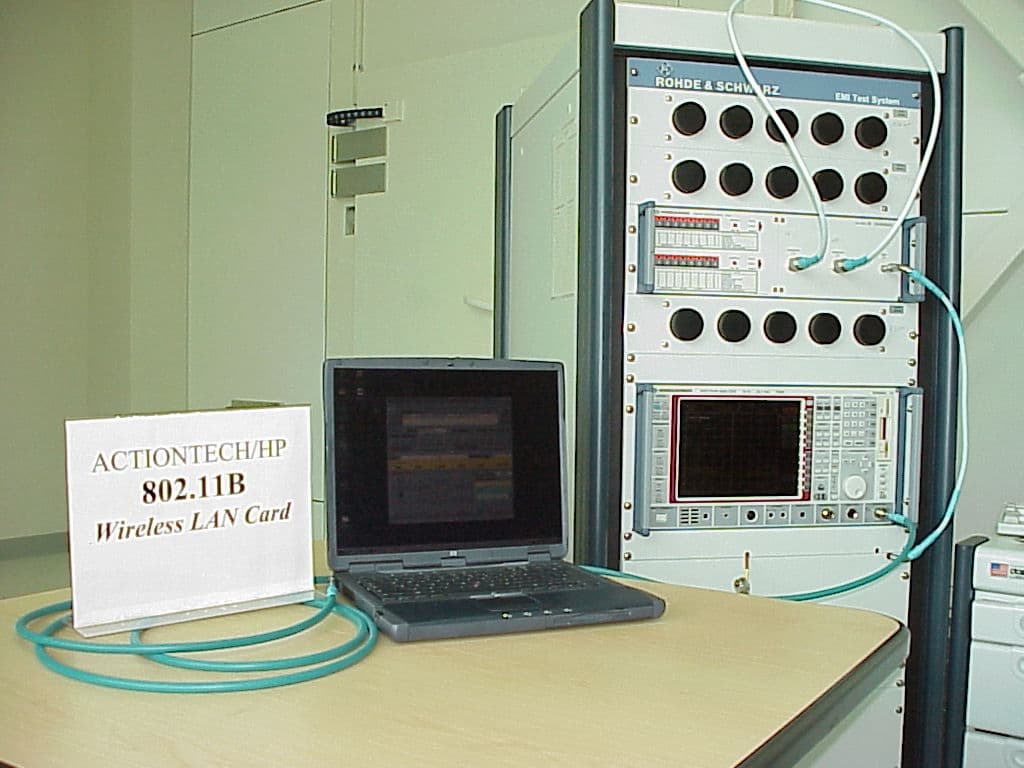
Click to zoom
Application Details
- Equipment Class
- DSS - Part 15 Spread Spectrum Transmitter
- Date of Grant
- Jul 26, 2001
- Application Purpose
- Original Equipment
- Date of Application
- May 31, 2001
- Equipment Note
- Laptop computer with wireless modem
- Frequency Range
- 2412.00000000 - 2462.00000000
- Company
- HP Inc.
- Country
- United States
Documents & Files
Document Text
Text extracted from the exhibit documents filed with the FCC. Open a document above to read the original.
Users Manual
1 Memorandum To: Reviewing examiner/engineer at FCC From: Phillip Inglis, TRP/Cetecom bvba Date: 06/01/01 Re: FCC ID:B94WLAN During the filing process Hewlett Packard decided to change the FCC ID from B946100 to B94WLAN. As a result of this change, the product identifier portion of FCCID listed on the Form 731 must be corrected from 6100 to WLAN. Please make this correction as requested by Hewlett Packard. Further, I would like to inform the reviewing staff that the user manual attached to this file is a generic manual applicable to all Laptops. As a result, it contained RF Exposure information typically required of all Laptops with wireless modems qualifying as mobile devices. This information sheet has been removed because it would be misleading to the user to leave it in manual. This unit has had SAR test data taken and the report submitted showing compliance with the RF Exposure limits. This data was taken with the laptop wireless antenna as close as possible to the body phantom. Thus, the recorded levels represent the maximum levels that an individual could be exposed to during any normal operation of the unit. Under these circumstances and in accordance with past Commission policy, the manual is not required to have any statement regarding RF Exposure. If anyone has any questions regarding the above information, please contact me at 410-531-3439, or via email at [email protected] Regards, Phillip Inglis TRP/Cetecom bvba
Attestation Statements
ctc_gn_01_00.doc (General);5/25/01 Page 1 of 1 This is to authorize Phil Inglis to act on CETECOM Inc. behalf for the HP Omnibook 6100 approval for the WLAN radio at the FCC. Sincerely, Lothar Schmidt CETECOM Inc. EMC AND BLUETOOTH CETECOM Inc. 411 Dixon Landing Road Milpitas, CA 95035 U.S.A. Phone: + 1 408 586 6200 Telefax: + 1 408 586 6299 e-mail: [email protected] URL: www.cetecom.com CETECOM Inc. 411 Dixon Landing Road - Milpitas, CA 95035 · U.S.A. Phil Inglis 14085 Howard Rd. Dayton, Md 21036 your reference your letter our reference direct dial + 1 408 586 6214 date 5/25/01
Cover Letter(s)
May 31, 2001 CONFIDENTIALITY REQUEST Federal Communications Commission Authorization and Evaluation Division 7435 Oakland Mills Road Columbia, MD 21046 Re:Hewlett Packard Co., Mobile Computing Division, Application for certification of laptop computers containing a spread spectrum transmitter: FCCID: xxxxxxx Gentlemen: Hewlett Packard Co., Mobile Computing Division, herein submits an Application for Equipment Authorization to be followed by submission of a fee for $1130.00 pursuant to Form 159 for certification of the reference product under FCC Rules Part 15 as required by the FCC Rules. Hewlett Packard Co., Mobile Computing Division, pursuant to 47CFR 0.459, requests post grant confidentiality for portions of the material contained in this application such that the identified material will be withheld from public inspection following the grant of this authorization. This material, as indicated by the request for confidentiality of the item during the electronic submission process and further identified below, includes: 1. Schematic diagrams 2. Block diagram 3. Parts list Specifically, these exhibits contain information relating to circuit function and complexity that could be of benefit to competitors. The material contains trade secrets and confidential information that Hewlett Packard Co., Mobile Computing Division, does not customarily release to the public and which is otherwise not generally available to the public. Please contact the undersigned by phone at 410-531-3439, by fax at 410-531-0807, by email at [email protected], or by correspondence at the address below if there are any further questions or additional information needed concerning this filing. Regards, (signed) Phillip Inglis, TRP/Cetecom b.v.b.a. 14085 Howard Rd. Dayton, MD. 21036
Cover Letter(s)
DECLARATION OF CONFORMITY According to ISO/IEC Guide 22 and EN 45014 Manufacturer’s Name: Manufacturer’s Address: Hewlett Packard Company Hewlett Packard Company Mobile Computing Division 19310 Pruneridge Ave. Cupertino, CA 95014 Declares, that the product(s): Product Name: Notebook PC Model Number(s): OmniBook 6100 and Pavilion series Notebook PC Product Options: Includes modemless, 3Com modems and 802.11b RF device Conforms to the following Product Specifications: Safety: IEC 60950: 1991 +A1,A2,A3,A4 / EN 60950: 1992 +A1,A2,A3,A4,A11 IEC 60825-1:1993 +A1 / EN 60825-1:1994 +A11 Class 1 LED GB4943-1995 EMC: CISPR 22:1997 / EN 55022: 1998 Class B [1] CISPR 24:1997 / EN 55024: 1998 IEC 61000-3-2:1995 / EN 61000-3-2:1995 +A1: 1998 +A2: 1998 IEC 61000-3-3:1994 / EN 61000-3-3:1995 GB9254-1998 FCC Title 47 CFR, Part 15 Class B/ANSI C63.4: 1992 AS/NZS 3548: 1995 Rules and Regulations of Class B Telecom: Notified Body Number: 0682 TBR 21: 1998, EG 201 121: 1998 Notified Body Address: Radio: Equipment Class 2 CETECOM ICT Services GmbH ETS 300-826 General EMC requirements for Radio equipment Untertuerkheimer Str. 6-10 ETS 300-328 Technical requirements for Radio equipment D-66117 Saarbruecken Supplementary Information : The product herewith complies with the requirements of the R&TTE Directive 1999/5/EC and carries the CE marking accordingly. [1] The product was tested in a typical configuration with Hewlett Packard Personal Computer peripherals. This device complies with Part 15 of the FCC Rules. Operation is subject to the following two conditions: (1) this device may not cause harmful interference, and (2) this device must accept any interference received, including interference that may cause undesired operation. The HP F1454A and F1781A AC/DC adapter used with this product is designed to operate on all power systems, other than IT power systems. Corvallis, OR, May 15, 2001 European Contact for regulatory topics only: Hewlett Packard GmbH, HQ-TRE, Herrenberger StraBe 130, 71034 Boeblingen, Germany. (FAX:+49-7031-143143). USA Contact: Hewlett Packard Co., Corporate Product Regulations Manager, 3000 Hanover Street, Palo Alto, CA 94304. Phone: (650) 857-1501.
External Photos
CETECOM Inc. Test report no.:141FCC/2001/A Issued date:2001-05-25 Page 48 (52) TEST SITE Radiated Emissions HP OMNIBOOK 6100 CETECOM Inc. Test report no.:141FCC/2001/A Issued date:2001-05-25 Page 49 (52) Conducted Emissions HP OMNIBOOK 6100
ID Label/Location Info
D D 1 2 3 4 5 6 7 ABCE 7 6 5 4 3 2 1 ECBA LTR NAME MODEL MATERIAL FINISH DATE SCALE UNIT MM DWG. NO. APPROVED DESIGNED DRAWN REV 3A 3A 3C TOL. + - 1 PLC2 PLCANGLE 7F, 116 HOU KANG ST. SHIN LIN, TAIPEI, TAIWAN, R.O.C. ITEMDESCRIPTION REVISIONS DESCRIPTION DATEAPP THE 3RD PROJECTION PART NO. Quanta Computer Inc. 2 1 3 FIRST RELEASE Rita S/N HCJT1016 1/1 HCJT1016 90.05.31 90.05.31 J T1 WIRELESS LABEL 3B Rita 0.1 0682 38.5 64.0 FCC ID : B94WLAN CANADA : Made in Taiwan
ID Label/Location Info
The following Equipment Label located on the bottom of the unit as shown. FCC ID Label
Internal Photos
HP Omnibook-6100 HP Omnibook-6100 MODULE Antenna is somewhere in this area Antenna is somewhere in this area
Operational Description
Basic Operation Principle of 802MIP Actiontec Electronics, Inc. 4/2001 The Wireless LAN portion of 802MIP combo card is a 2.4GHz ISM Band DSSS Radio. It is designed to operate using IEEE 802.11b WLAN Standard for use in wireless networking systems. The Radio consists of 4 major ICs, which are ISL3685, HFA3783, ISL3984, ISL3874, and few support ICs. It operates at maximum transmit rate 11Mb/s, back off rates 5.5, 2 and 1 Mb/s. The modulation schemes include CCK (Complementary Code Keying), DQPSK and DBPSK depending on what transmit bit rate it operates at. The radio card interfaces to PC through a MiniPCI bus. Transmitter path The Ethernet data comes through the MiniPCI interface, the Host I/O interface to the MAC section of ISL3874. The signal then flows into the data router where it is converted from Ethernet to 802.11b protocol. After the signal is converted, a radio preamble and header is added to it and passed to the I/O of BBP (Base Band Processor) section of ISL3874 via PHY I/O, RADIO I/O. There is also support circuitry, such as outboard SRAM and flash ROM, which contains the firmware controlling the radio. In TX modulator of BBP section, differential phase shift keying modulation schemes DBPSK, DQPSK and CCK, with data scrambling capability, are fulfilled to provide a variety of data rates--DBPSK for 1 Mb/s, DQPSK for 2 Mb/s and CCK for 5.5 and 11Mb/s. The signal, which now is two separate quadrature components I and Q, then flows to the quad IF chip HFA3783 through D/A converters. At TX side of BBP, there is also TX ALC (Automatic Level Control) circuitry, which is part of the TX ALC loop. The loop keeps TX output power to be consistent so that prevent the power spectrum from regrowth. HFA3783 is now the dual up conversion mixers (dual down conversion mixers for RX). The signal upconverts to an IF frequency of 374 MHz and passes into a variable gain amplifier, which is also a part of the ALC loop. Next, it passes through the switched TX/RX shared SAW filter into ISL3685 and then upconverts again to a RF frequency from 2.412~2.484 GHz, depending on the channel selection. The signal flows through a pre-amplifier, two band pass filters, which block all the unwanted emissions such as image components, harmonics and spurious stuff, into ISL3984 power amplifier. The output of the power amplifier is then fed through another band pass filter that is about 85 MHz bandwidth to one of the antennas. Receiver path The receive signal traveling through the air is received by the dual diversity antennas. The circuits will switch to the antenna which provides better RSSI (Received Signal Strength Indication). The RF signal then feeds into an 85 MHz band pass filter, which blocks all the unwanted components such as image frequency. The signal again is amplified using the LNA within ISL3685 and mixed down to the IF frequency of 374 MHz. The PLL and synthesizer select the channel frequency using Low Side Injection. The mixer outputs are then fed through the IF SAW filter that provides image rejection into HFA3783, which is now a quad down converter. HFA3783 also provides RSSI to BBP of ISL3874. There is a two stage analog AGC (Automatic Gain Control) circuit which adjusts the gain to compensate the signal strength differences. The output of the twin AGC’s provides a constant level signal to the I and Q down converters, which convert the IF to both I and Q signals to BBP. A second frequency synthesizer, which uses ISL3183 as its VCO, feeds the I and Q mixers with a same frequency signal that is phase shifted by 90°. The I and Q signals that are fed into BBP of ISL3874 are converted into digital signals via a dual A/D converters then flow through the digital AGC control circuit followed by the digital demodulator. The correlation codes that BBP generates properly detect the transmitted complimentary codes. In here the automatic antenna selection is also done by taking RSSI as the reference. The output of the digital demodulator is sent into an I/O interface of MAC section. The digital codes then flow into the PHY I/O interface and into the MAC protocol engine. The MAC of ISL3874 converts the signal protocol from 802.11b to Ethernet and finally passes that data through the HOST I/O interface to the PC.
Operational Description
Product Information Form: Name of Company :Hewlett-Packard Co., Mobile Computing Division Street Address :1000 NE Circle Blvd. City/Zip Code :Corvallis, OR 97330 Country :USA Contact Person :Kathy Warnock Telephone :541-715-2171 Fax :541-715-3607 e-mail :[email protected] Manufacturer :Orient Semiconductor Electronics, Ltd. Name of EUT :802MIP(W) installed into HP OmniBook 6100 Description :Mini PCI 802.11b Wireless Card Model No. :802MIP(W) Serial No. : FCC-ID : Frequency Band of Operation : 2.412 – 2.484 GHz Type of Modulation:DBPSK at 1Mb/s; DQPSK at 2Mb/s; CCK at 5.5 ,11Mb/s No. of Channels :13 Channels in EU Antenna Type : Power Supply : 5.0V ± ±± ±10% Output Power :15 dBm Extreme Vol. Limits: Extreme Temp. Tolerance : 0° °° °C – 55° °° °C
RF Exposure Info
1365 Adams Court, Menlo Park, CA 94025 Hewlett Packard Company., Model No: 802MIP (W)Date of Test: May 23 & 24, 2001 File: 20504871Page 1 of 43RSS-102 & FCC Part 2 SAR Evaluation Table of Contents 1.0JOB DESCRIPTION................................................................................................................2 1.1Client Information..........................................................................................................2 1.2Equipment under test (EUT)...........................................................................................2 1.3Test plan reference..........................................................................................................3 1.4System test configuration................................................................................................3 1.4.1System block diagram & Support equipment......................................................3 1.4.2Test Position......................................................................................................4 1.4.3Test Condition....................................................................................................6 1.5Modifications required for compliance............................................................................6 1.6Additions, deviations and exclusions from standards.......................................................6 2.0SAR EVALUATION.................................................................................................................7 2.1SAR Limits....................................................................................................................7 2.2Configuration Photographs.............................................................................................8 2.4Evaluation Procedures..................................................................................................17 2.5Test Results..................................................................................................................18 3.0TEST EQUIPMENT...............................................................................................................21 3.1Equipment List.............................................................................................................21 3.2Muscle Tissue Simulating Liquid..................................................................................22 3.3E-Field Probe Calibration.............................................................................................22 3.4Measurement Uncertainty.............................................................................................23 3.5Measurement Tractability.............................................................................................23 4.0WARNING LABEL INFORMATION - USA........................................................................24 5.0REFERENCES........................................................................................................................25 5.0DOCUMENT HISTORY........................................................................................................26 APPENDIX A - SAR Evaluation Data................................................................................................27 APPENDIX B - E-Field Probe Calibration Data................................................................................35 1365 Adams Court, Menlo Park, CA 94025 Hewlett Packard Company., Model No: 802MIP (W)Date of Test: May 23 & 24, 2001 File: 20504871Page 2 of 43RSS-102 & FCC Part 2 SAR Evaluation 1.0JOB DESCRIPTION 1.1 Client Information The Omnibook 802MIP (W) has been tested at the request of Company:Hewlett Packard Company Mobile Computing Division 1000 NE Circle Blvd. Corvallis, OR 97330 Name of contact:Ms. Kathy Warnock Telephone:(541) 715-2171 Fax (541) 715-3607 1.2 Equipment under test (EUT) Product Descriptions: EquipmentHP Omnibook 6100 Series (with Mini PCI 802.1 lb wireless card) Trade NameHewlett Packard CompanyP/N.802MIP (W) FCC ID Not Labeled S/N No.Not Labeled Category Portable RF ExposureUncontrolled Environment Frequency Band 2412 – 2462 MHzSystemFHSS EUT Antenna Description TypeDipoleConfigurationFixed DimensionsN/AGain0 dBi LocationInside the laptop Use of Product: Manufacturer:SAME as above. Production is planned:[X] Yes, [ ] No EUT receive date:May 23, 2001 EUT received condition:Good working condition prototype Test start date:May 23, 2001 Test end date:May 24, 2001 1365 Adams Court, Menlo Park, CA 94025 Hewlett Packard Company., Model No: 802MIP (W)Date of Test: May 23 & 24, 2001 File: 20504871Page 3 of 43RSS-102 & FCC Part 2 SAR Evaluation 1.3Test plan reference FCC rule part 2.1093, FCC Docket 96-326 & Supplement C to OET Bulletin 65 1.4System test configuration 1.4.1System block diagram & Support equipment Support Equipment Item #EquipmentModel No.Serial No. 1Hewlett Packard Omnibook61000Not Labeled S: Shielded U: Unshielded m: meters 1 Power Adaptor 115 V AC, 60 Hz EUT Transmitter 1 m, U 2 m, U 1365 Adams Court, Menlo Park, CA 94025 Hewlett Packard Company., Model No: 802MIP (W)Date of Test: May 23 & 24, 2001 File: 20504871Page 4 of 43RSS-102 & FCC Part 2 SAR Evaluation 1.4.2Test Position Figure 1: Laptop Upside Down Figure 2: Laptop in Normal Open Position Flat Phantom Back of the Laptop Flat Phantom Back of the Display Back of the Laptop 1365 Adams Court, Menlo Park, CA 94025 Hewlett Packard Company., Model No: 802MIP (W)Date of Test: May 23 & 24, 2001 File: 20504871Page 5 of 43RSS-102 & FCC Part 2 SAR Evaluation Figure 3: Laptop on Left Side Flat Phantom Back of the Laptop Back of the Display 1365 Adams Court, Menlo Park, CA 94025 Hewlett Packard Company., Model No: 802MIP (W)Date of Test: May 23 & 24, 2001 File: 20504871Page 6 of 43RSS-102 & FCC Part 2 SAR Evaluation 1.4.3Test Condition During tests the worst case data (max RF coupling) was determined with following conditions: EUT AntennaFixed lengthOrientationN…
Text truncated - open the document above for the full version.
Test Report
Brief Explanations on Processing Gain Data 1. The formula of Processing Gain is: Gp = (S/N)o +Mj + Lsys Where Gp: Processing Gain; (S/N)o: the ratio of signal energy vs noise power density. Based on the data provided by the chip set manufacturer, it is 16.4dB @11Mb/s, 13.4dB @5.5Mb/s, 13.3dB @2.0Mb/s, 10.3dB @1.0Mb/s; Lsys: test system loss. The measurement result to our test set-up is 2.0dB; Mj: Jamming Margin. It is the ratio of jammer vs WLAN channel signal; 2. The purpose of the measurement here is to figure out Mj at different frequencies. Processing Gain will be gotten through calculation based on the above formula at different frequencies; 3. During the tests (see the Block Diagram of Test Set-up), the input signal to RX is about –60dBm (not exactly at –60dBm) and Mj (dB) = Jammer level (dBm) – Channel signal level (dBm); 4. The criteria we define the transmission link failure is: PER = 8%; 5. FCC defines that when testing the Processing Gain for a specific channel, if the frequency is fo, the jammer frequency has to scan from fo-8.5 MHz to fo+8.5MHz with 50 KHz per step. In another word, 340 data will be taken just for a single channel measurement; 6. Having calculated out 340 Processing Gains for a specific channel, use the percentile average function of Microsoft Excel to figure out the final result. Example: see the first row of 11Mb/s @ Channel 6 Frequency—Jammer frequency = fo-8.5 =2437-8.5 = 2428.50 MHz; (S/N)o—16.4 dB @11 Mb/s (see Item 1); Lsys—2.0 dB (see Item 1); PER— 8.0%, which is the failure criteria; Jammer— -57.2dBm, which is the Jammer level @ PER=8.0%; Mj—Jamming Margin. 5.5 (dB) = -57.2 (dBm) – (-62.7) (dBm) (see Item 3). On here, also see the next page of spread sheet, which shows that XMIT level = -62.7 dBm); Gp—Processing Gain = (S/N)o + Mj + Lsys = 16.4 + 5.5 + 2.0 = 23.9 (dB). After having calculated out 340 Gps, use the percentile function of Microsoft Excel, the final Gp of 11Mb/s @ Ch 6 is 12.9 dB. At the same time, incorporate those 340 data into f—Gp chart, you’ll get a whole picture of it. Chip/symbol rate, the symbol/bit rate and the Chip/bit Bit rate Chip/symbol rate Bit/symbol rate Chip/bit rate Gp (dB) Spec (dB) 1 Mbit/sec 11 1, DBPSK 11 13.2 10 2 Mbit/sec 11 2, DQPSK 5.5 12.6 10 5.5 Mbit/sec 8 4, CCK 2 13.4 10 11 Mbit/sec 8 8, CCK 1 12.9 10 Note: 1. Gp is Processing Gain; 2. Spec is Processing Gain specifications defined by FCC on DSSS systems.
Test Report
CETECOM Inc. CETECOM Inc. 411 Dixon Landing Road, Milpitas, CA-95035, USA Phone: +1 408 586 6200 Fax: +1 408 586 6299 www.cetecomusa.com Issued test report consists of 52 Pages Page 1 (52) Test report no.: 141FCC/2001/A FCC Part 15.247 HP OmniBook 6100 RECOGNIZED BY INDUSTRY CANADA IC - 3925 CETECOM Inc. Test report no.:141FCC/2001/A Issued date:2001-05-25 Page 2 (52) Table of Contents 1 General information 1.1 Notes 1.2 Testing laboratory 1.3 Details of applicant 1.4 Application details 1.5 Test item 1.6 Test standards 2 Technical test 2.1 Summary of test results 2.2 Test report 1 General information 1.1 Notes The test results of this test report relate exclusively to the test item specified in 1.5. The CETECOM Inc. USA does not assume responsibility for any conclusions and generalisations drawn from the test results with regard to other specimens or samples of the type of the equipment represented by the test item. The test report may only be reproduced or published in full. Reproduction or publication of extracts from the report requires the prior written approval of the CETECOM Inc. USA. CETECOM Inc. Test report no.:141FCC/2001/A Issued date:2001-05-25 Page 3 (52) 1.2 Testing laboratory CETECOM Inc. 411 Dixon Landing Road, Milpitas, CA-95035, USA Phone: +1 408 586 6200 Fax: +1 408 586 6299 E-mail: [email protected] Internet: www.cetecomusa.com 1.3 Details of applicant Name : Hewlett Packard Co.; Mobile Computing Division Street : 1000 NE Circle Blvd. City : Corvallis, OR 97330 Country : USA Telephone : +1 541 715 2171 Telefax : +1 541 715 3607 Contact : Kathy Warnock e-mail : [email protected] 1.4 Application details Date of receipt of application : 2001-04-01 Date of receipt of test item : 2001-04-15 Date of test : 2001-04-18/19/20 1.5 Test item Manufacturer : Hewlett Packard. Address : See above Name of EUT : HP OmniBook 6100 Series (with Mini PCI 802.11b wireless card) Type Designation : Model : Additional informations: HP OmniBook 6100 Series 802MIP(W) Frequency : 2.412 – 2.484 GHz Type of modulation : DBPSK at 1Mb/s; DQPSK at 2Mb/s; CCK at 5.5.and 11Mb/s Number of channels : 11 Channels in US Antenna : Integral Power supply : 5.0V Type of equipment : Temperature range : 0°C - +35°C Tests were carried out at the maximum number of channels available (13) in the test software. The US version will set to 11 channels only. 1.6 Test standards FCC Part 15 §15.247 The tests were done following the public notice DA 00-705 released March 30, 2000 CETECOM Inc. Test report no.:141FCC/2001/A Issued date:2001-05-25 Page 4 (52) 2 Technical test 2.1 Summary of test results No deviations from the technical specification(s) were ascertained in the course of the tests performed. Technical responsibility for area of testing : 2001-05-10 EMC& Radio Lothar Schmidt Date Section Name Signature CETECOM Inc. Test report no.:141FCC/2001/A Issued date:2001-05-25 Page 5 (52) 2.2 Testreport TEST REPORT Testreport no. : 141FCC/2001/A HP OmniBook 6100 CETECOM Inc. Test report no.:141FCC/2001/A Issued date:2001-05-25 Page 6 (52) TEST REPORT REFERENCE LIST OF MEASUREMENTS Paragraph PARAMETER TO BE MEASURED PAGE Transmitter parameters § 15.247 (a)(2) Spectrum Bandwith of a DSSS System 7 § 15.247 (b)(1) Maximum peak output power 11 § 15.247 (c)(1) Emission limitations 16 § 15.247 (d) Power Spectral Density 33 § 15.247 (e) Processing Gain of DSSS System 37 Receiver parameters § 15.209 Spurious radiations - Radiated 39 Test equipment listing 47 Test Site 48 Photographs of the equipment 50 ANNEX: Details about processing gain. NOTE: Conducted Emissions as per § 15.107 are not applicable for the EUT since it is a built in a laptop computer. The Laptop was measured in accordance with FCC part 15 B including the Wireless LAN . CETECOM Inc. Test report no.:141FCC/2001/A Issued date:2001-05-25 Page 7 (52) SPECTRUM BANDWITH OF DSSS-SYSTEM SUBCLAUSE § 15.247 (a)(2) TEST CONDITIONS 6 dB BANDWIDTH ( kHz ) Frequency (MHz) 2412 2442 2472 T nom ( 20 )° °° °C V nom (5.0)V 10220 95190 96192 Measurement uncertainty ±3dB LIMIT SUBCLAUSE §15.247(a) (2) The minimum 6dB bandwith shall shall be at least 500 KHz CETECOM Inc. Test report no.:141FCC/2001/A Issued date:2001-05-25 Page 8 (52) SPECTRUM BANDWITH OF DSSS-SYSTEM SUBCLAUSE § 15.247 (a)(2) 2412 MHz LIMIT SUBCLAUSE §15.247(a) (2) The minimum 6dB bandwith shall shall be at least 500 KHz , here 10.02 MHz ANALYZER SETTINGS: RBW=100KHz , VBW=1MHz CETECOM Inc. Test report no.:141FCC/2001/A Issued date:2001-05-25 Page 9 (52) SPECTRUM BANDWITH OF DSSS-SYSTEM SUBCLAUSE § 15.247 (a)(2) 2442 MHz LIMIT SUBCLAUSE §15.247(a) (2) The minimum 6dB bandwith shall shall be at least 500 KHz , here 11.42 MHz ANALYZER SETTINGS: RBW=100KHz , VBW=1MHz CETECOM Inc. Test report no.:141FCC/2001/A Issued date:2001-05-25 Page 10 (52) SPECTRUM BANDWITH OF DSSS-SYSTEM SUBCLAUSE § 15.247 (a)(2) 2472 MHz LIMIT SUBCLAUSE §15.247(a) (2) The minimum 6dB bandwith shall shall be at least 500 KHz , here 10.02 MHz ANALYZER SETTINGS: RBW=100KHz , VBW=1MHz CETECOM Inc. Test report no.:141FCC/2001/A Issued date:2001-05-25 Page 11 (52) MAXIMUM PEAK OUTPUT POWER SUBCLAUSE § 15.247 (b) (1) (CONDUCTED) TEST CONDITIONS MAXIMUM PEAK OUTPUT POWER (dBm) Frequency (MHz) 2412 2442 2472 Pk 13.94 Pk 14.50 Pk 13.05 T nom ( 23 )° °° °C V nom (5.0)V Av 8.29 Av 8.29 Av 7.28 Pk 13.14 Pk 12.60 Pk 12.09 T nom ( 0 )° °° °C V nom (5.0)V Av 7.85 Av 7.16 Av 6.59 Pk 12.43 Pk 11.09 Pk 10.33 T nom ( 35 )° °° °C V nom (5.0)V Av 6.46 Av 5.93 Av 5.12 Measurement uncertainty ±3dB LIMIT SUBCLAUSE § 15.247 (b) (1) Frequency range RF power output 2400-2483.5 MHz / 5725 – 5850 MHz 1.0 Watt CETECOM Inc. Test report no.:141FCC/2001/A Issued date:2001-05-25 Page 12 (52) MAXIMUM PEAK OUTPUT POWER (EIRP) SUBCLAUSE § 15.247 (b) (1) (RADIATED) TEST CONDITIONS MAXIMUM PEAK OUTPUT POWER (dBm) Frequency (MHz) 2412 2442 2472 Pk11.75 Pk10.45 Pk 10.46 T nom ( 23 )° °° °C V nom (5.0)V Av5.85 Av4.28 Av 3.18 Maximum deviation from output power under extreme…
Text truncated - open the document above for the full version.
Test Setup Photos
CETECOM Inc. Test report no.:141FCC/2001/A Issued date:2001-05-25 Page 48 (52) TEST SITE Radiated Emissions HP OMNIBOOK 6100 CETECOM Inc. Test report no.:141FCC/2001/A Issued date:2001-05-25 Page 49 (52) Conducted Emissions HP OMNIBOOK 6100
Contact Information
Applicant
Richard P Tarsio(US Canada Technical Regulations)
Technical Contact
TRP/Cetecom bvbaPhillip Inglis
[email protected]410 531 3439
14085 Howard Rd · Dayton, Maryland · United States
Non-Technical Contact
TRP/Cetecom bvbaPhillip Inglis
[email protected]410 531 3439
Test Firm
Cetecom ICT Services GmbHRalf Hoehn
Technical Specifications
| # | Rule Parts | Frequency Range | Power Output |
|---|---|---|---|
| 1 | 15C | 2.41 GHz - 2.46 GHz | 28.00 mW |
Other Applications from HP Inc.
B94HNI70CBVN
Aug 14, 2026Model HSN-I70C
Equipment Class
CBE - Citizens Band End User DevicesB94HNQ38C3BEK
Jun 03, 2026Notebook PC
Equipment Class
TNB - Licensed Non-Broadcast Station TransmitterB94HNI65C4BLV
Apr 23, 2026Notebook Computer HSN-I65C-4
Equipment Class
PCB - PCS Licensed TransmitterB94HNI67C4BLV
Apr 23, 2026Notebook Computer HSN-I67C-4
Equipment Class
CBE - Citizens Band End User DevicesB94HNI66C4SPY
Feb 03, 2026Model HSN-I66C-4
Equipment Class
PCB - PCS Licensed Transmitter