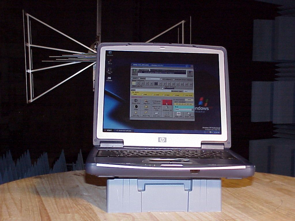
B94ZT1000WLANWLAN Card for HP notebook
HP Inc.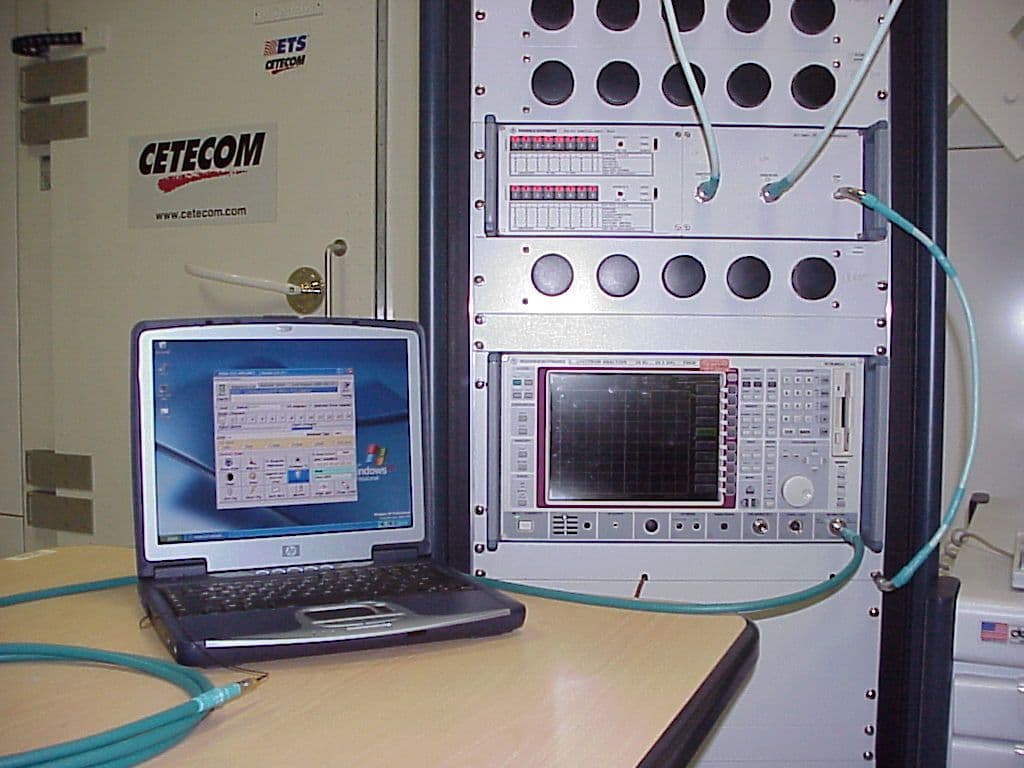
Click to zoom
Application Details
- Equipment Class
- DSS - Part 15 Spread Spectrum Transmitter
- Date of Grant
- Dec 19, 2001
- Application Purpose
- Original Equipment
- Date of Application
- Dec 19, 2001
- Equipment Note
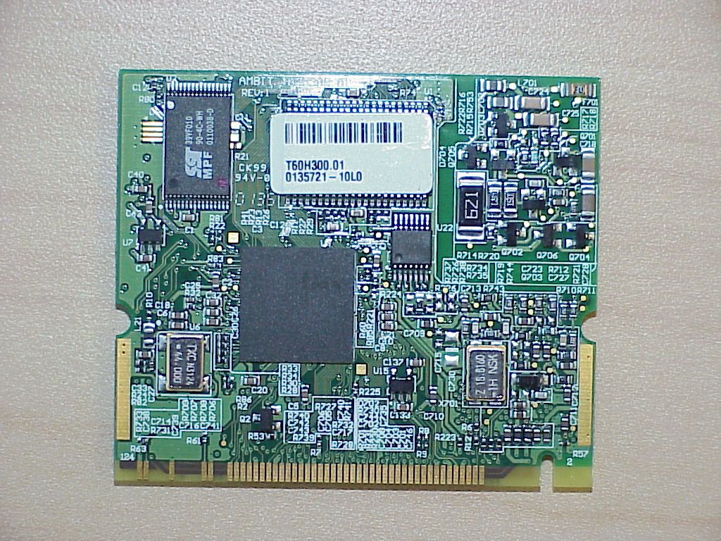
- WLAN Card for HP notebook
- Frequency Range
- 2412.00000000 - 2462.00000000
- Company
- HP Inc.
- Country
- United States
Documents & Files
Document Text
Text extracted from the exhibit documents filed with the FCC. Open a document above to read the original.
Users Manual
Contents Chapter 1 About the WLAN Combo Card 1-1 Features 1-2 Applications 1-3 Product Kit Chapter 2 Network Configuration and Planning 2-1 Network Topology 2-2 Roaming Chapter 3 Adapter Installation and Configuration – Windows ® 98 / NT / 2000 3-1 System Requirements 3-2 Inserting the Adapter 3-3.1 802.11b WLAN Driver Installation - Windows ® 98 3-3.2 Adapter Configuration - Windows ® 98 3-3.3 Protocol Installation - Windows ® 98 3-4 802.11b WLAN Setup for Windows ® 2000 Chapter 4 Installing and Navigating the PRISM Configuration Utility 4-1 LAN-Express Configuration Utility - Installation 4-2 LAN-Express Configuration Utility - Navigation Appendix A Troubleshooting Appendix B Glossary Chapter 1 About the WLAN Combo Card The IEEE 802.11 WLAN Combo Card is compatible with any standard, notebook computer Type III MiniPCI slot. Upon successful installation, the WLAN Combo card will communicate seamlessly with other 802.11B wireless home and office networking products. 1-1 FEATURES 1. Supports up to 11 Mbps data rate: T-1 line alternative/replacement that dramatically cuts costs. 2. Working range up to 800 ft. in an open environment enhances mobility. 3. Supports point-to-point and point-to-multipoint access provides increased flexibility. 4. Seamless connectivity to wired Ethernet and PC network LAN’s offers quick, trouble-free integration with existing networks. 5. Robust Direct Sequence Spread Spectrum (DSSS) technology provides secure, interference-resistant wireless connection. 6. Wireless connections eliminate the hassle and cost of cabling. 7. Supports a wide range of LAN (Local Area Network) Network Operating Systems (NOS) including Windows ® 98 and Windows ® 2000 8. Omni - directional antenna included 9. Greater flexibility to locate or move networked PC’s 1-2 APPLICATIONS 802.11B WLAN offer a fast, reliable, cost-effective solution for wireless client access to the network the following applications and environments: ß Remote access to corporate network information ß E-mail, file transfer and terminal emulation ß Difficult-to-wire environments ß Historic or older buildings ß Buildings with asbestos insulation ß Open areas where wiring is difficult to employ ß Frequently changing environments ß Retailers, manufacturers or other organizations that frequently rearrange the workplace or relocate ß Temporary LANs for special projects or peak time usage ß Trade shows, exhibitions and construction sites that employ temporary networks. Retailers, airline and shipping companies that need additional workstations for a peak period and Auditors that require workgroups at customer sites. ß Access to database for mobile workers ß Medical, Technical and Retail specialists that require roaming access to a database or other network resources. ß SOHO (Small Office and Home Office) users ß Perfect for users that need a small, easy-to-install network that deploys rapidly. ß Inter-building connection ß Wireless building-to-building networks are quickly and easily installed, require no monthlylease fees, and provide the flexibility to reconfigure easily. 1-3 PRODUCT KIT The WLAN 802.11b WLAN product kit includes the following items. Ensure that the items in the following list have been included. If any of the listed items are missing, please contact your local dealer. ß 1 X Type III WLAN MiniPCI Adapter ß 1 X Driver ß 1 X User Manual & Utility Chapter 2 Network Configuring and Planning The WLAN supports legacy Ethernet LAN network configuration options as defined by the IEEE 802.11 standards committee. The 802.11B WLAN can be configured as: . Ad-Hoc for departmental or SOHO LANs. . Infrastucture for enterprise LANs. . LAN-Interconnection for to point-to-point link as a campus backbone. 2-1 Network Topology An Ad-Hoc wireless LAN is a group of computers. Each equipped with on 802.11B WLAN adapter, connected as an independent wireless LAN.Computers in a specific Ad-Hoc wireless LAN must be configured to share the same radio channel. Ad-Hoc wireless LAN configurations are appropriate for branch level departments or SOHO operations. The 802.11B WLAN provides access to a wired LAN for wireless workstations.An integrated wireless and wired LAN is called an Infrastructure configuration. A group of 802.11B WLAN PC users and an Access Point compose a Basic Service Set (BSS).Each 802.11B WLAN can talk to any computer in the wired LAN infrastructure via the Access Point. An Infrastructure configuration extends the accessibility of a 802.11B WLAN equipped PC to a wired LAN and doubles the effective wireless transmission range for 2 802.11B WLAN PCs. Since the Access Point is able to forward data within its BSS, the effective transmission range in an infrastucture LAN is doubled. 2-2 Roaming Infrastructure mode also supports roaming capabilities for mobile users More than one BSS can be configured as an Extended Service Set (ESS). The continuous network allows users to roam freely within an ESS. All 802.11B WLAN PCs and Access Point within one ESS must be configured with the same ESSID and use the same radio channel. Before enabling an ESS with roaming capability, choosing a feasible radio channel and optimum Access Point position is recommended. Proper Access Point positioning combined with a clear radio signal will greatly enhance performance. Chapter 3 Adapter Installation and Configuration – Windows ® 98 / 2000 3-1 SYSTEM REQUIREMENTS In order to install and use the WLAN Combo card your PC system must meet the following requirements: ß A Type III MiniPCI slot ß MiniPCI revision 2.10 compliant card and socket services ß Windows 98 (with the Floppy, for use during installation) ß 500 Kbytes free disk space for utility and driver installation 3-2 INSERTING THE ADAPTER To insert the WLAN Network Adapter into a notebook computer, do the following: 1. Locate an available Type II or Type III MiniPCI slot. 2. With the MiniPCI Adapter’s 124-pin connector facing the MiniPCI slot, the MiniPCI Adapter completely into the M…
Text truncated - open the document above for the full version.
Users Manual
HP Notebook PC Reference Guide 2 Reference Guide Notice This manual and any examples contained herein are provided “as is” and are subject to change without notice. Hewlett-Packard Company makes no warranty of any kind with regard to this manual, including, but not limited to, the implied warranties of merchantability and fitness for a particular purpose. Hewlett-Packard Co. shall not be liable for any errors or for incidental or consequential damages in connection with the furnishing, performance, or use of this manual or the examples herein. Consumer transactions in Australia and the United Kingdom: The above disclaimers and limitations shall not apply to Consumer transactions in Australia and the United Kingdom and shall not affect the statutory rights of Consumers. © Copyright Hewlett-Packard Company 2000–2001. All rights reserved. Reproduction, adaptation, or translation of this manual is prohibited without prior written permission of Hewlett-Packard Company, except as allowed under the copyright laws. The programs that control this product are copyrighted and all rights are reserved. Reproduction, adaptation, or translation of those programs without prior written permission of Hewlett-Packard Co. is also prohibited. Portions of the programs that control this product may also be copyrighted by Microsoft Corporation, SystemSoft Corp., Insyde Software Corporation, S3 Graphics Incorporated, and Adobe Systems Incorporated. See the individual programs for additional copyright notices. This product incorporates copyright protection technology that is protected by method claims of certain U.S. patents and other intellectual property rights owned by Macrovision Corporation and other rights owners. Use of this copyright protection technology must be authorized by Macrovision Corporation and is intended for home and other limited viewing uses only unless otherwise authorized by Macrovision Corporation. Reverse engineering or disassembly is prohibited. Microsoft®, MS-DOS®, and Windows® are U.S. registered trademarks of Microsoft Corporation. Pentium® and the Intel Inside logo are U.S. registered trademarks and Celeron™ and SpeedStep™ are U.S. trademarks of Intel Corporation. Adobe® and Acrobat® are trademarks of Adobe Systems Incorporated. Hewlett-Packard Company HP Notebook Customer Care 1000 NE Circle Blvd., MS 425E Corvallis, OR 97330 Reference Guide 3 Important Safety Information CAUTION To reduce the risk of fire, use only No. 26 AWG or larger telecommunications line cord to connect a modem to the telephone wall jack. When using your computer with a telephone connection, always follow basic safety precautions to reduce the risk of fire, electric shock, and injury to persons: • Do not use this product with a telephone connection near water (for example, near a bathtub, sink, swimming pool, or in a wet basement). • Avoid using a telephone connection (other than a cordless type) during an electrical storm. There may be a remote risk of electric shock from lighting. • Do not use a telephone connection of any type to report a gas leak while in the vicinity of the leak. • Use only the power cord and batteries indicated in this manual. Do not dispose of batteries in a fire. They may explode. Check with local codes for possible special disposal instructions. HP Software Product License Agreement Your HP product contains software programs. CAREFULLY READ THIS LICENSE AGREEMENT BEFORE PROCEEDING TO OPERATE THIS EQUIPMENT. RIGHTS IN THE SOFTWARE ARE OFFERED ONLY ON THE CONDITION THAT THE CUSTOMER AGREES TO ALL TERMS AND CONDITIONS OF THE LICENSE AGREEMENT. PROCEEDING TO OPERATE THE EQUIPMENT INDICATES YOUR ACCEPTANCE OF THESE TERMS AND CONDITIONS. IF YOU DO NOT AGREE WITH THE TERMS OF THE LICENSE AGREEMENT, YOU MUST NOW EITHER REMOVE THE SOFTWARE FROM YOUR HARD DISK DRIVE AND DESTROY THE MASTER DISKETTES, OR RETURN THE COMPLETE HP PRODUCT AND SOFTWARE FOR A FULL REFUND. PROCEEDING WITH CONFIGURATION SIGNIFIES YOUR ACCEPTANCE OF THE LICENSE TERMS. UNLESS OTHERWISE STATED BELOW, THIS HP SOFTWARE LICENSE AGREEMENT SHALL GOVERN THE USE OF ALL SOFTWARE THAT IS PROVIDED TO YOU AS PART OF THE HP PRODUCT AND SHALL SUPERSEDE ANY OTHER SOFTWARE WARRANTY STATEMENT THAT MAY BE INCLUDED IN THIS HP PRODUCT OR MAY BE FOUND ONLINE. Operating system and software applications by Microsoft are licensed to you under the Microsoft License Agreement contained in the Microsoft documentation or displayed on your screen when Microsoft Software Products are launched. 4 Reference Guide For a PC supplied with a Microsoft operating system: When you start the PC and accept the Microsoft End-user License Agreement (“EULA”), your license rights are valid only if a Certificate of Authenticity (“COA”) label corresponding to your Microsoft operating system is provided with your PC. The COA label can usually be found on the bottom of the computer. If the COA label does not correspond to your Microsoft operating system or is missing, contact your HP reseller for details. Other non-HP Software and Operating Systems are covered by the appropriate vendor license. The following License Terms govern the use of the HP software: USE. Customer may use the software on any one HP product. Customer may not network the software or otherwise use it on more than one HP product. Customer may not reverse assemble or decompile the software unless authorized by law. COPIES AND ADAPTATIONS. Customer may make copies or adaptations of the software a) for archival purposes or (b) when copying or adaptation is an essential step in the use of the software with an HP product so long as the copies and adaptations are used in no other manner. OWNERSHIP. Customer agrees that he/she does not have any title or ownership of the software, other than ownership of the physical media. Customer acknowledges and agrees that the software is copyrighted and protected under the copyright laws. Customer acknowledges and agrees that the software may have been developed by a th…
Text truncated - open the document above for the full version.
Block Diagram
12/21/00 ISL37400M System Overview PRISM 2.5 miniPCIRadio Block Diagram ISL37400M HFA3783 QUAD IF ISL3685IR RF/IF CONV ISL3984 RFPA PLL RF LO REF IN PLL I/Q LO I ADC Q ADC RX ADC IF DAC RX DAC TX DAC Q DAC I DAC IF LO REF IN TX ADC REF_OUT TX ALC MOD DEMOD AGC CTL I/O ANT_SEL 6 1 1 1 6 6 6 6 6 REF IN 44 MHz CLOCK PHY I/O CONTROL PROCESSOR MEMORY ARBITER RADIO I/O HOST I/O WEP ENGINE CAL_EN T/R Optional Parallel FLASH miniPCI HOST Intf Differential signals ISL3874 MAC/BBP 128Kx16 SRAM RF VCO 2023– 2125MHz ISL3183 IF VCO 748MHz 32KHz Sleep SAW External Antenna Optional Diversity Switch External Status LEDs Serial EEPROM
Cover Letter(s)
Federal Communication Commission Equipment Authorization Division, Application Processing Branch 7435 Oakland Mills Road Columbia, MD 21048 November 15, 2001 TO WHOM IT MAY CONCERN Pursuant to Paragraphs §0.457 and 0.459 of the Commission’s Rules (47 C.F.R.) and Section §552(b)(4) of the Freedom of Information Act, Hewlett Packard requests confidentiality for the following products: FCC ID B94xt1000WLAN For the product stated above, we request that the following information be held confidential: 1) Electrical Schematics of the Circuitry No other items submitted as part of the equipment authorization filing process are deemed confidential. The above exhibits contain Hewlett Packard trade secrets and proprietary information that could be of benefit to our competitors regarding the design of our mobile handset. This material is not customarily available to the general public and we request that it be withheld from public inspection. If you have any questions, please feel free to contact me at the address shown below. Sincerely, Lothar Schmidt Technical Manager EMC/Radio
ID Label/Location Info
287.629 mm INPUT: 3.16-3.30A (3,16-3,30A) 19 V Apparatus Claims of U.S. Patent Nos. 4,631,603, 4,577,216, 4,819,098, and 4,907,093 licensed for limited viewing uses only. SEE MANUAL FOR BATTERY AND AC ADAPTER INFORMATION. PREL1 + - COMPLIES WITH CANADIAN EMC CLASS B REQUIREMENTS. Conforme à la classe B des normes Canadiennes de compatibilité électromagnétiques <<CEM>>. hp omnibook xt1000 MP 3 fn * 7 8 9 - 5 6 4 + 1 2 3 0 / . f1 f2 f3 f4 f5 f6 esc f7 f8 f9 f10 f11 f12 Q W E R T U I O P A SD F G H J K L X C V B N M 2 3 Z sys rq break prt sc pause home end 6 7 Y 8 9 0 ^ * ( ) _ - + = { [ " ' < , > . ? / ctrl altalt } ] | \ 1 4 5 insert delete : ; ~ ` ctrl # & ! $ % @ ROM R O M ROM PROCESSOR LABEL, 3rd party *Intel *AMD *Other . . . Microsoft OS Label *Pentium II *Pentium III *Celeron *Other Line up ng hp omnibook x t1000 hp omnibook x t1000 hp pavilion z t1000 Identity, Printed & Molded Icons, Bottom Case Label Layout, & Product Color Reference Graphic Plan 1x F____-______ J ZINFANDEL N. Buchanan 03.16.00 1 1 A As ISSUED Art Work 02.28.01 go,ds TITLE PROGRAM PART NUMBER DESIGNER SCALE DATE SHEET #1 IS ARTWORK SPECIFICATION DRAWING SHEET REVISION hp mcd user interaction design SYM REVISIONS APPROVEDDATE FILENAME: /ZIN_GPrJ.eps ID -1860 Artwork Number OF COLOR REQUIREMENTS: ZINFANDEL - Graphics Plan _________________________________________________ Identity, Icon Graphics, Bottom Case Labels, Graphics & Product Color Plan FRONT BUTTON MARKINGS: @ 90 degree projection. rev.J illustrator rendering reference - 06.28.01 hp restricted View 2: Inside Surfaces View 6: I/O Panel View 3: Top Case View 8: Front View 5: Right End View 7: Bottom Case View 4: CD Player Detail (90 degree projection for 1:1 graphic application) parallel vga (2) usb s-video mic line out dc power in COLOR CODED (MicroSoft Standard) CONNECTORS I/O Icons PRINTED = PMS 538C, blue white MODEM Icons PRINTED = PMS 538C, blue white PLASTIC = ZIN Blue PLASTIC = ZIN Blue FIREWIRE Icon PRINTED = PMS 538C, blue white USB & Wireless Icon PRINTED = PMS 538C, blue white (color coded MS tandard connector) AUDIO Icon PRINTED: = PMS 538C, blue white (color coded MS standard connector) KENSINGTON Lock Icon PRINTED: = Caribbean Light Blue hp pn 6009-0260 PRIMARY KyBd Legends PRINTED = PMS 538C (see keyboard layout specifications) FN Shift Legends PRINTED = PMS 646C, blue (see keyboard layout specifications) KEY CAP PLASTIC = ZIN Blue KEYBOARDS: NEW Revised 'fonts & icons' (see individual local language keyboard art work for specifications) 24x LOCAL LANGUAGES: = current localization mix AUDIO Icons PRINTED = PMS 538C, blue white PLASTIC = ZIN Blue AUDIO BUTTONS = ZIN Blue CD Marking MOLDED: 0.3mm recessed LED Icons: BLUE HOT KEY BUTTONS: Button Plastic = William Silver 2 Ring Plastic = CLEAR Lighted Ring LED = Blue Legend Icons = ZIN Blue hp LOGO PRINTED = ZIN Blue SPEAKER HOLE AREA (B) = ZIN Blue SPEAKER HOLE AREA (A): Painted, = William Silver 2 POWER Icon PRINTED = PMS 8001C, metalic silver POWER BUTTON: Button Plastic = Ashley Blue FRONT BUTTON MARKINGS: SEE VIEW #4 FOR ARTWORK SPECIFIC GRAPHICS APPLICATION FRONT BUTTON MARKINGS: SEE VIEW #4 FOR ARTWORK SPECIFIC GRAPHICS APPLICATION FRONT BUTTON MARKINGS: SEE VIEW #4 FOR ARTWORK SPECIFIC GRAPHICS APPLICATION SCROLL Graphic PRINTED = PMS 653C, blue hp s ub-brand : Printed p lastic part for insertion (not a label), 1) P LASTIC PART = ZIN Blue 2) SUB-BRAND IDNETITY PRINTED = Caribbean L ig ht Blue, hp p n 6009-0260 TRACKPAD OFF Icon PRINTED = ZIN Blue 3rd PARTY LABEL Placement: 1) Intel Processor Label 2) Microsoft OS Label RESET ICON PRINTED = PMS 538C, blue white PolkAudio Logo PRINTED = Caribbean Light Blue, hp pn 6009-0260 Bar-Code Label, Stepped SurfaceLabel area:1 7.0 x 51.0 mm (bottom case surface)Clear Window area: 24.0 x 57.0 mm with a 3.5mm shelf standing above bottom case surface( plus a standing rib, 1.0 mm wide x 0.3mm tallthat stands above shelf surface at the outside dimen.) TELECOM LABELING: 1.0 mm wide x 0.6 mm tall standing rib above the surface with 0.15mm tolerance on each side for the application of a 62.0mm Wide X 60.0mm Tall label. GENERIC Regulatory Label 1) Label background = ZIN Blue 2) Label Content = Caribbean Light Blue 1.0 mm wide x 0.3 mm tall standing rib above the surface HP Bar-Code Label location: Label applied to recess area, clear protective film applied to stepped area between product surface and standing rib. View 1: Left End hp LOGO Molded, 0.3mm recessed & polished PLASTIC = ZIN Blue PLASTIC = ZIN Blue PLASTIC = ZIN Blue RUBBER FOOT = ZIN Blue RUBBER FOOT = ZIN Blue BATTERY LATCH BUTTON = ZIN Blue RUBBER FOOT = ZIN Blue RUBBER FOOT = ZIN Blue lATCH BUTTON = ZIN Blue PLASTIC = ZIN Blue PLASTIC = ZIN Blue PLASTIC = ZIN Blue PAINTED: = William Silver 2 PAINTED: William Silver 2 LATCH Plastic = ZIN Blue PAINTED = William Silver 2 PLASTIC = ZIN Blue PLASTIC = ZIN Blue PLASTIC = ZIN Blue BUTTON = ZIN Blue PAINTED = William Silver 2 BUTTONS PAINTED = William Silver 2 PAINTED = William Silver 2 LED ICONS = ZIN Blue BUTTONS PAINTED = William Silver 2 MODE BUTTON: William Silver 2 TRACK PAD & SCROLL: Lexan Printed = = William Silver 2 LED: Green LENS Color = Clear Surrounding LENS Window = William Silver 2 CD BUTTON ICONS: = ZIN Blue PLASTIC = ZIN Blue LED = Clear Lens LED WINDOW = Clear Lens TRACK PAD ON/OFF BUTTON = William Silver 2 TRACK L&R SHOLDERS: Clear Lens PLASTIC = ZIN Blue RUBBER PLUG = ZIN Blue PLASTIC = ZIN Blue SCREEN BEZEL: Painted = William Silver 2 RUBBER PLUG = ZIN Blue RUBBER PLUG = ZIN Blue SCREEN BEZEL: Painted = William Silver 2 RUBBER PLUG = ZIN Blue SUSPEND SWITCH = ZIN Blue LATCH Plastic = ZIN Blue WIRELESS Button PLASTIC: Clear Lens Button GRAPHIC: Molded, raised 0.3mm STANDARD REGULATORY SYMBOL LABEL (62.0mm Wide X 37.75mm Tall) Regulatory Symbol Label & HP Prime Label Location. 1) Label background = ZIN Blue 2) Label Content: = Caribbean Light Blue, hp pn 6009-0260 1.0 mm wide x 0.6mm tall standing rib above the surface with 0.15 toler…
Text truncated - open the document above for the full version.
ID Label/Location Info
F C C S ta nda rds F or T es ted comply With operation of the device. FCC ID : B94zt1000WLAN or B94zt1000BT any interference ,including interference that may cause undesired Operation is subject to the following two conditions :(1) this device may cause interference ,and (2) this device must accept This device contain a radio. ( refer to manual ) CANADA : xxxx xxxx xxxx or xxxx xxxx xxxx Modem L a bel on the la ptop Wireles s L a bel on the la ptop
Operational Description
UNLEASHINGTHE POWER OF CONNECTIVITY™ Intersil’s PRISM ® 2.5 wireless networking chip set, utilizing the ISL3874 integrated Baseband Processor and Medium Access Controller, is optimized for smaller form factors and embedded WLAN applications. Embedded designs such as mini-PCI or Compact Flash® are installed within a product during assembly. This allows reduction of overall system size, requires no user installation, and is usually less prone to problems. The PRISM 2.5 solution incorporates sophisticated state-of-the-art silicon germanium (SiGe) and sub- micron CMOS technology to create highly-integrated, feature-rich WLAN silicon solutions for products operating in the 2.4 GHz Industrial Scientific and Medical (ISM) band at the IEEE 802.11b-compliant high-data-rate speed of 11 Megabits-per-second (Mbps). PRISM 2.5 consists of only four ICs and a companion voltage-controlled oscillator (VCO). PRISM 2.5-based products will provide users with wireless access to networks and the Internet for fast and efficient transmission of data, video and Voice over Internet Protocol (VoIP) services. Intersil is also developing a PRISM 2.5 mini-PCI Reference Design. • ISL3984 - 2.4GHz Power Amplifier and Detector • ISL3685 - 2.4GHz RF/IF Converter and Synthesizer • HFA3783 - I/Q Modulator/Demodulator Synthesizer • ISL3874A - Integrated MAC and Baseband Processor with PCI products PRISM ® 2.5, 11Mbps with Mini-PCI interface SPECIFICATIONS Variable Data Rates11, 5.5, 2 and 1Mbps Frequency Band 2.4GHz ISM Band BER 1x10 -5 at -83dBm Dual ModeIEEE802.11, 1 and 2Mbps 5.5 and 11Mbps Range100m Indoors* Power ConsumptionSame as PRISM II *Range test using AND-C-107 omnidirectional antenna. PRISM 2.5, 11Mbps Chip Set Block Diagram (Mini-PCI) 6 7 6 6 6 6 7 1 1 AGC CTL RAKE TX ALC AND DEMOD RF DAC IF DAC I ADC Q ADC TX DAC TX ADC I DAC Q DAC MOD I/O AND FILTER IF I/Q LO RF LO PLL PA ON-CHIP ROM PC CARD HOST INTERFACE PHY INTER- FACE LO MINI_PCI SERIAL CONTROL (MMI) ISL3874A (MDI) MICRO- PRO- GRAMMED MAC ENGINE WEP ENGINE MEM- ORY CON- TROLLER ON-CHIP RAM THRESH. DETECT. MEDIUM ACCESS CONTROLLER BASEBAND PROCESSOR 44MHz PLL VCO OSC VCO HOST COMPUTER INTERFACE FLASH MEMORY SRAM RX TX LNA 32kHz OSC ISL3685 (FILE #4860) RF/IF CONVERTER ISL3984 (FILE #4862) ISL3183 HFA3783 (FILE #4633) IF I/Q MOD/DEMOD ISL3874A MAC/BBP (FILE #4868) 1751 PR2.5 MiniPCI Product 7/31/01 10:55 AM Page 1
RF Exposure Info
CETECOM Inc. 411 Dixon Landing Road Milpitas, CA 95035 Federal Communication Commission Authorization and Evaluation Division 7435 Oakland Mills Road Columbia, MD 21046 Attention: Reviewing Engineer The Ambit WLAN card used in the HP notebooks is a regular 802.11b Wireless LAN Card using spread spectrum technique for wireless access of a PC to a LAN using a miniPCI interface inside the PC. Due to the construction and the intended use of the of a the HP notebooks with the built in WLAN Card, the radio installation is done in the factory and not user installed. Due to the construction of the notebook and the location of the antennas (TX and RX) a minimum distance under normal operating conditions of more than 2.5 cm (2.8 to 3 cm depending on the angle of the screen) is guaranteed. The calculation was made for this worst case. The maximum peak output power for this device is 46.6 mW (16.69 dBm). Calculation of EIRP of the equipment for 20 dBm (0.0100 W); equivalent to 8.66 V/m in 20 cm distance Regarding MPE limits, GPUC environment limits maximum exposure to 1 mW/cm 2. The power density is: at 20 centimeters from an antenna for 100mW S = E 2 /3770=-13 H 2 = 0.01989 mW/cm 2 < 1 mW/cm 2 at 10 centimeters from an antenna for 100mW S = E 2 /3770=-13 H 2 = 0.0795 mW/cm 2 < 1 mW/cm 2 at 2.5 centimeters from an antenna for the actual power (46.6 mW) S = E 2 /3770=-13 H 2 = 0.5941 mW/cm 2 < 1 mW/cm 2 Where: S = Power density (mW/cm 2) E = electrical field strength (V/m) Calculations are based on standard formula for calculating field strength at a distance and converting power density using free space impedance. Compliance is shown for the built in module, which has an internal antenna with a unique connector. T he module and the antenna are not accessible for the user of the notebook. The minimum distance of 2.5 is given by the position of the antenna in the lower part of the Displays as worst case of the different variant tested. If you should have any questions regarding this submission, please feel free to contact the undersigned. Yours tr ul y, Lothar Schmidt Technical Manager EMC/Radio CETECOM Inc.
Test Report
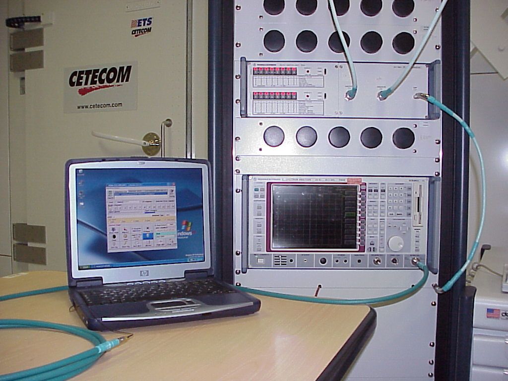
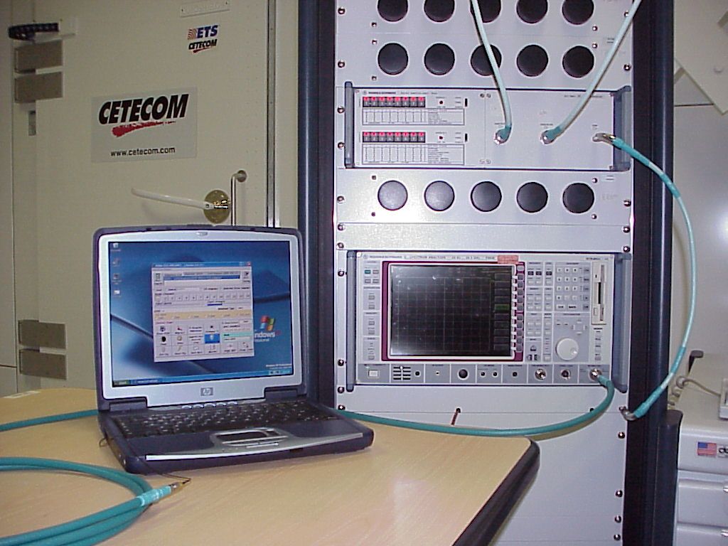
CETECOM Inc. CETECOM Inc. 411 Dixon Landing Road, Milpitas, CA-95035, USA Phone: +1 408 586 6200 Fax: +1 408 586 6299 www.cetecom.com Issued test report consists of 48 Pages Page 1 (48) Test report no.: 173FCC/2001_2WLAN FCC Part 15.247 FCC ID: B94xt1000WLAN (HP Omnibook xt1000) FCC LISTED, REG. NO.: 101450 & RECOGNIZED BY INDUSTRY CANADA IC – 3925 CETECOM Inc. Test report no.: 173FCC/2001_2WLAN Issued date:2001-10-25 Page 2 (48) Table of Contents 1 General information 1.1 Notes 1.2 Testing laboratory 1.3 Details of applicant 1.4 Application details 1.5 Test item 1.6 Test standards 2 Technical test 2.1 Summary of test results 2.2 Test report 1 General information 1.1 Notes The test results of this test report relate exclusively to the test item specified in 1.5. The CETECOM Inc. USA does not assume responsibility for any conclusions and generalisations drawn from the test results with regard to other specimens or samples of the type of the equipment represented by the test item. The test report may only be reproduced or published in full. Reproduction or publication of extracts from the report requires the prior written approval of the CETECOM Inc. USA. TEST REPORT PREPARED BY: EMC & Radio Engineer: Harpreet Sidhu 1.2 Testing laboratory CETECOM Inc. 411 Dixon Landing Road, Milpitas, CA-95035, USA Phone: +1 408 586 6200 Fax: +1 408 586 6299 E-mail: [email protected] Internet: www.cetecom.com CETECOM Inc. Test report no.: 173FCC/2001_2WLAN Issued date:2001-10-25 Page 3 (48) 1.3 Details of applicant Name : Hewlett Packard Street : 19310 Pruneridge Av. City : Cupertino, CA Country : Contact : USA Richard Barbin Telephone : 408 343 7972 Telefax : 408 343 7366 e-mail : [email protected] 1.4 Application details Date of receipt of application : 2001-07-10 Date of receipt of test item : 2001-09-26 Date of test : 2001-09-26/27/28 1.5 Test item Manufacturer : applicant Name of EUT : T60H300.01 installed into HP Omnibook xt1000 Description : 802.11b wireless card Model No. : T60H300.01 Serial No. : FCC ID : N/A B94xt1000WLAN Additional informations Frequency : 2.412 – 2.462 GHz for US, 2.412 – 2.472 GHz for EU Type of modulation : DBPSK at 1Mb/s; DQPSK at 2Mb/s; CCK at 5.5.11Mb/s Number of channels : 11 Channels in US, 13 Channels in EU Antenna : Internal Power supply : 3.3V Output power : 15dBm Extreme Vol. Limits : Extreme Temp. Limits : 2.97V – 3.63V 0°C - +40°C 1.6 Test standards : FCC Part 15 §15.247 CETECOM Inc. Test report no.: 173FCC/2001_2WLAN Issued date:2001-10-25 Page 4 (48) 2 Technical test 2.1 Summary of test results No deviations from the technical specification(s) were ascertained in the course of the tests performed. Technical responsibility for area of testing : 2001-10-25 EMC & Radio Lothar Schmidt Date Section Name Signature CETECOM Inc. Test report no.: 173FCC/2001_2WLAN Issued date:2001-10-25 Page 5 (48) 2.2 Testreport TEST REPORT Testreport no. : 173FCC/2001_2WLAN FCC ID: B94xt1000WLAN (HP Omnibook xt1000) CETECOM Inc. Test report no.: 173FCC/2001_2WLAN Issued date:2001-10-25 Page 6 (48) TEST REPORT REFERENCE LIST OF MEASUREMENTS Paragraph PARAMETER TO BE MEASURED PAGE Transmitter parameters § 15.247 (a)(2) Spectrum Bandwith of a DSSS System 7 § 15.247 (b)(1) Maximum peak output power 11 § 15.247 (c)(1) Emission limitations 19 § 15.247 (d) Power Spectral Density 37 § 15.107 Conducted emissions 41 Receiver parameters § 15.209 Receiver Spurious Radiation 43 Test equipment listing 48 CETECOM Inc. Test report no.: 173FCC/2001_2WLAN Issued date:2001-10-25 Page 7 (48) SPECTRUM BANDWITH OF DSSS-SYSTEM SUBCLAUSE § 15.247 (a)(2) TEST CONDITIONS 6 dB BANDWIDTH ( kHz ) Frequency (MHz) 2412 2437 2462 T nom ( 23 )°C V nom ( 3.3)V 9919 9619 9919 Measurement uncertainty ±3dB LIMIT SUBCLAUSE §15.247(a) (2) The minimum 6dB bandwith shall shall be at least 500 KHz CETECOM Inc. Test report no.: 173FCC/2001_2WLAN Issued date:2001-10-25 Page 8 (48) SPECTRUM BANDWITH OF DSSS-SYSTEM SUBCLAUSE § 15.247 (a)(2) Low Channel: 2412 MHz LIMIT SUBCLAUSE §15.247(a) (2) The minimum 6dB bandwith shall shall be at least 500 KHz ANALYZER SETTINGS: RBW=100KHz , VBW=1MHz CETECOM Inc. Test report no.: 173FCC/2001_2WLAN Issued date:2001-10-25 Page 9 (48) SPECTRUM BANDWITH OF DSSS-SYSTEM SUBCLAUSE § 15.247 (a)(2) Mid Channel: 2437 MHz LIMIT SUBCLAUSE §15.247(a) (2) The minimum 6dB bandwith shall shall be at least 500 KHz ANALYZER SETTINGS: RBW=100KHz , VBW=1MHz CETECOM Inc. Test report no.: 173FCC/2001_2WLAN Issued date:2001-10-25 Page 10 (48) SPECTRUM BANDWITH OF DSSS-SYSTEM SUBCLAUSE § 15.247 (a)(2) High Channel: 2462 MHz LIMIT SUBCLAUSE §15.247(a) (2) The minimum 6dB bandwith shall shall be at least 500 KHz ANALYZER SETTINGS: RBW=100KHz , VBW=1MHz CETECOM Inc. Test report no.: 173FCC/2001_2WLAN Issued date:2001-10-25 Page 11 (48) MAXIMUM PEAK OUTPUT POWER SUBCLAUSE § 15.247 (b) (1) (CONDUCTED) TEST CONDITIONS MAXIMUM PEAK OUTPUT POWER (dBm) Frequency (MHz) 2412 2437 2462 Pk 17.74 Pk 18.91 Pk 19.67 T nom ( 23 )°C V nom (3.3)V Av 10.60 Av 12.06 Av 12.65 Measurement uncertainty ±3dB LIMIT SUBCLAUSE § 15.247 (b) (1) Frequency range RF power output 2400-2483.5 MHz / 5725 – 5850 MHz 1.0 Watt CETECOM Inc. Test report no.: 173FCC/2001_2WLAN Issued date:2001-10-25 Page 12 (48) MAXIMUM PEAK OUTPUT POWER SUBCLAUSE § 15.247 (b) (1) (CONDUCTED) L…
Text truncated - open the document above for the full version.
Contact Information
Applicant
Richard P Tarsio(US Canada Technical Regulations)
Technical Contact
CETECOM Inc.Lothar Schmidt
[email protected]408-586-6214
411 Dixon Landing Road · Milpitas, California · United States
Non-Technical Contact
CETECOM Inc.Lothar Schmidt
[email protected]408-586-6214
Test Firm
Cetecom Inc.Lothar Schmidt
Technical Specifications
| # | Rule Parts | Frequency Range | Power Output |
|---|---|---|---|
| 1 | 15C | 2.41 GHz - 2.46 GHz | 47.21 mW |
Other Applications from HP Inc.
B94HNI70CBVN
Aug 14, 2026Model HSN-I70C
Equipment Class
CBE - Citizens Band End User DevicesB94HNQ38C3BEK
Jun 03, 2026Notebook PC
Equipment Class
TNB - Licensed Non-Broadcast Station TransmitterB94HNI65C4BLV
Apr 23, 2026Notebook Computer HSN-I65C-4
Equipment Class
PCB - PCS Licensed TransmitterB94HNI67C4BLV
Apr 23, 2026Notebook Computer HSN-I67C-4
Equipment Class
CBE - Citizens Band End User DevicesB94HNI66C4SPY
Feb 03, 2026Model HSN-I66C-4
Equipment Class
PCB - PCS Licensed Transmitter