BCE-SAT-REMWireless Telephone Headset Transceiver
GN Audio USA Inc.
Click to zoom
Application Details
- Equipment Class
- DXT - Part 15 Low Power Transceiver, Rx Verified
- Date of Grant
- Nov 23, 1998
- Application Purpose
- Original Equipment
- Date of Application
- Sep 26, 1998
- Equipment Note
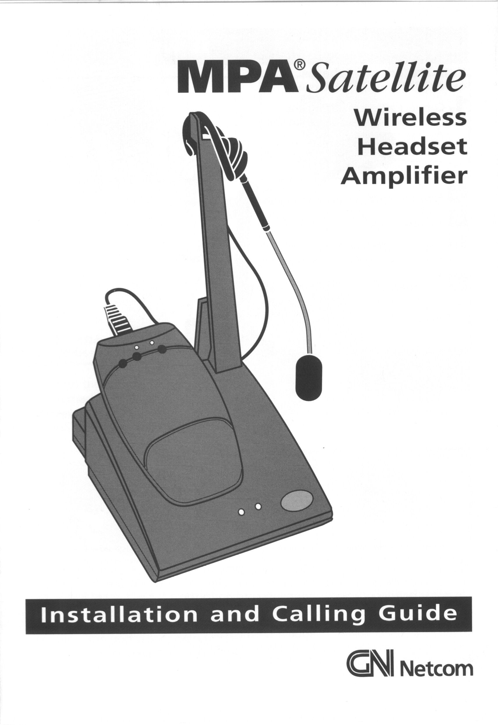
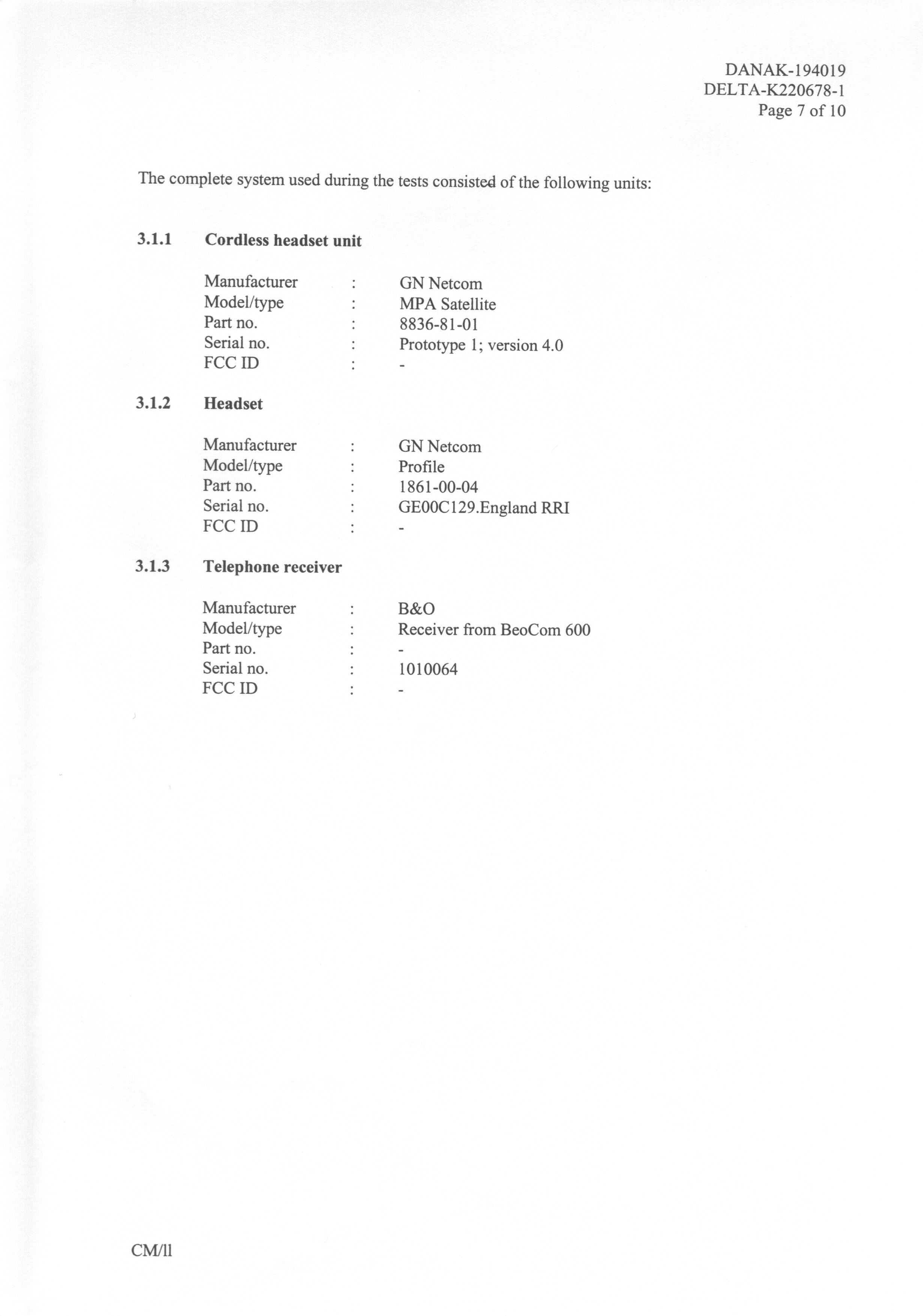
- Wireless Telephone Headset Transceiver
- Frequency Range
- 904.00916000 - 905.16996000
- Company
- GN Audio USA Inc.
- Country
- United States
Documents & Files



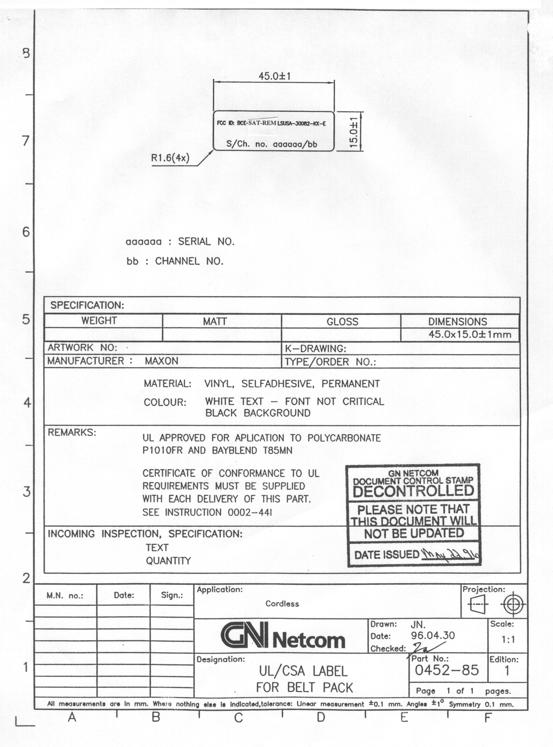
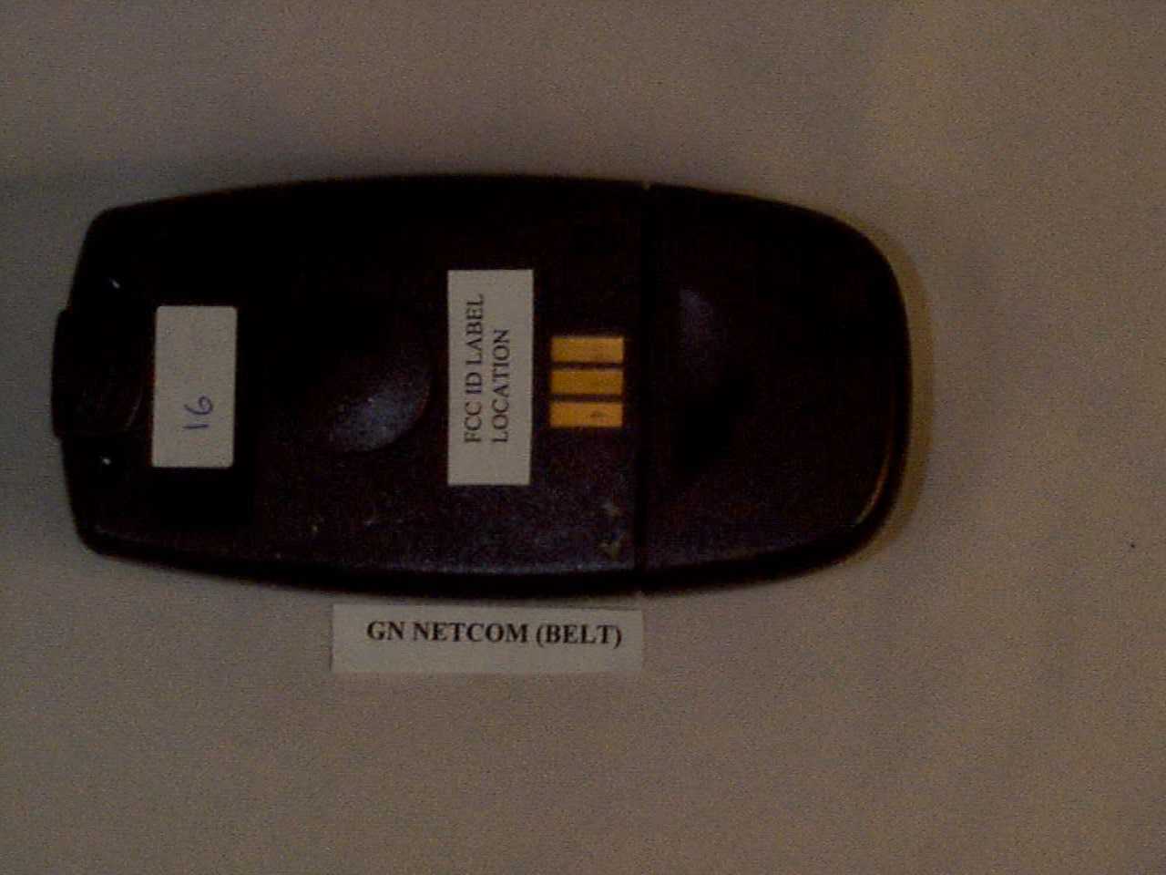
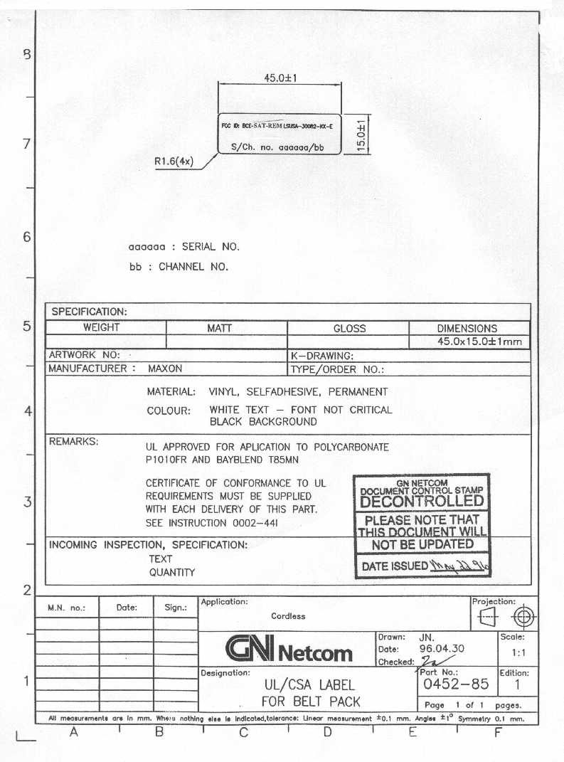
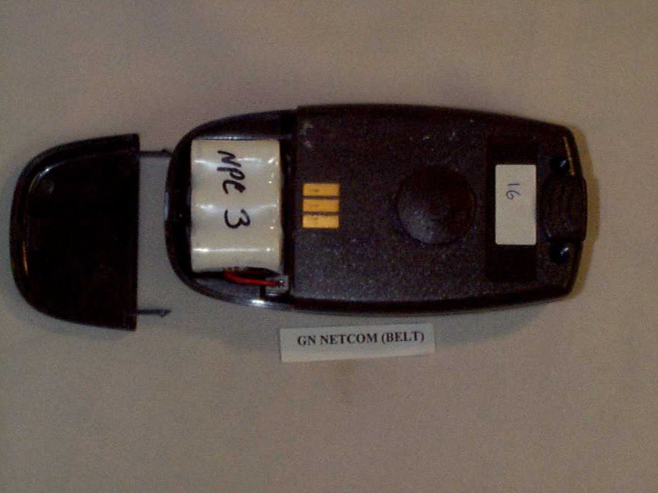
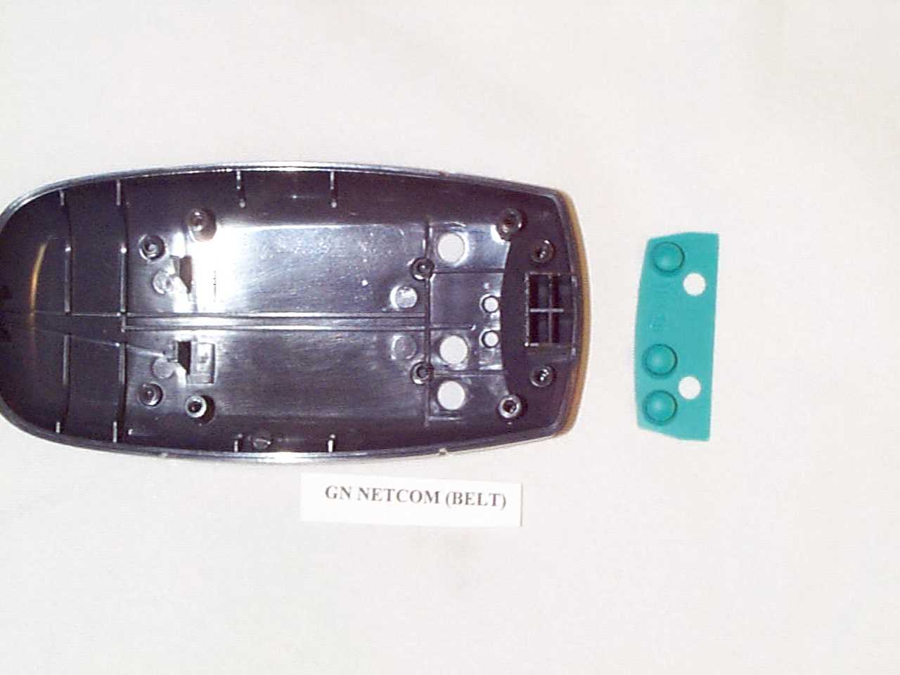
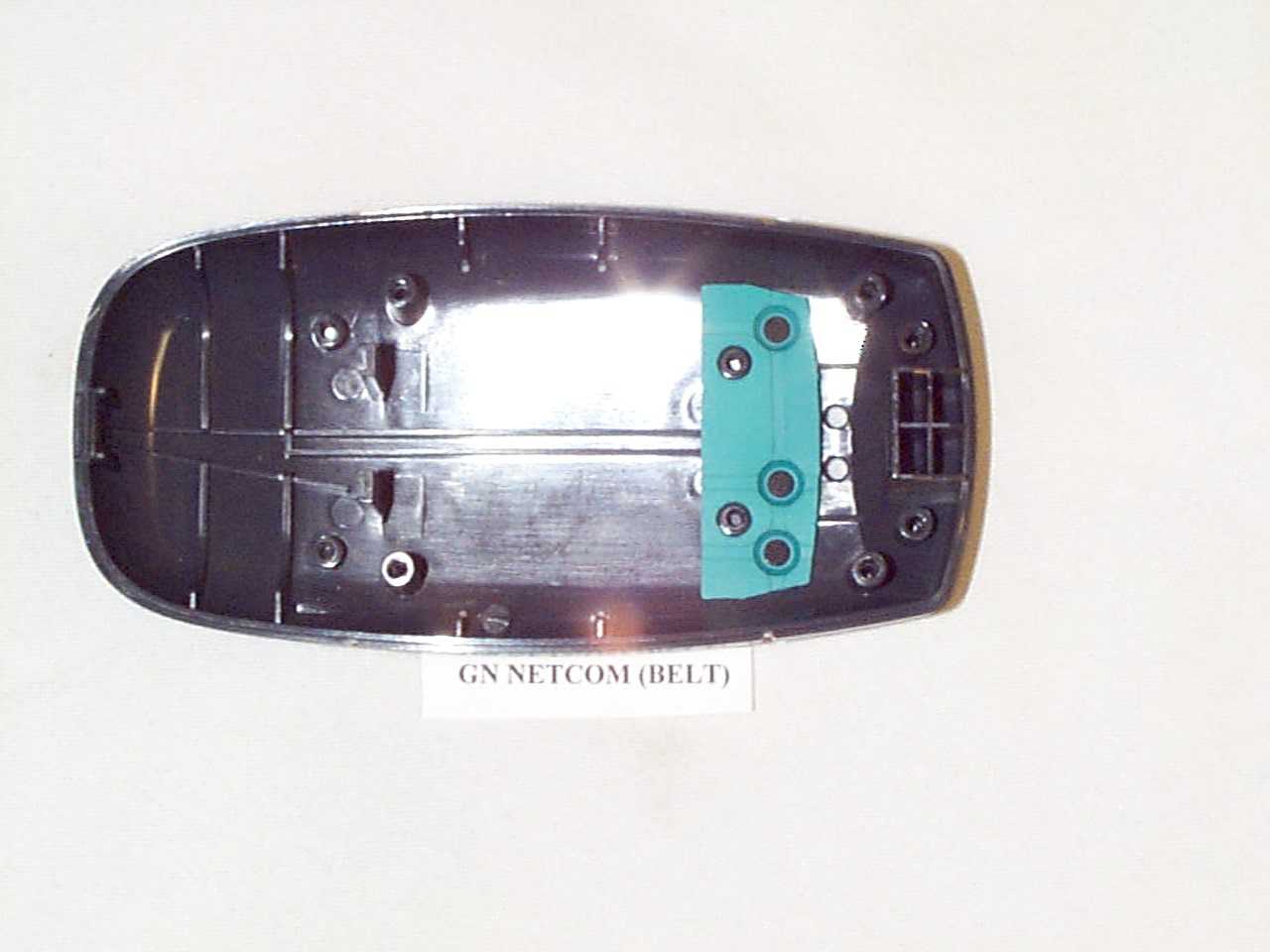
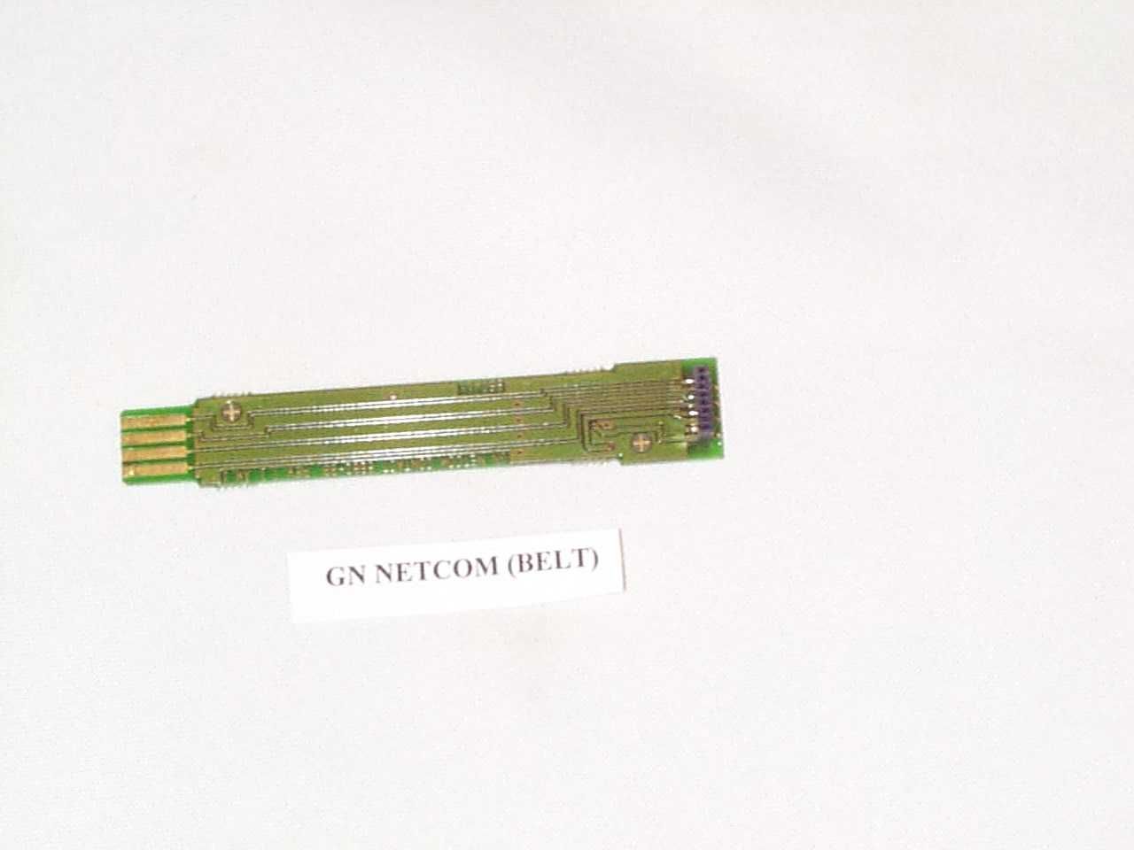
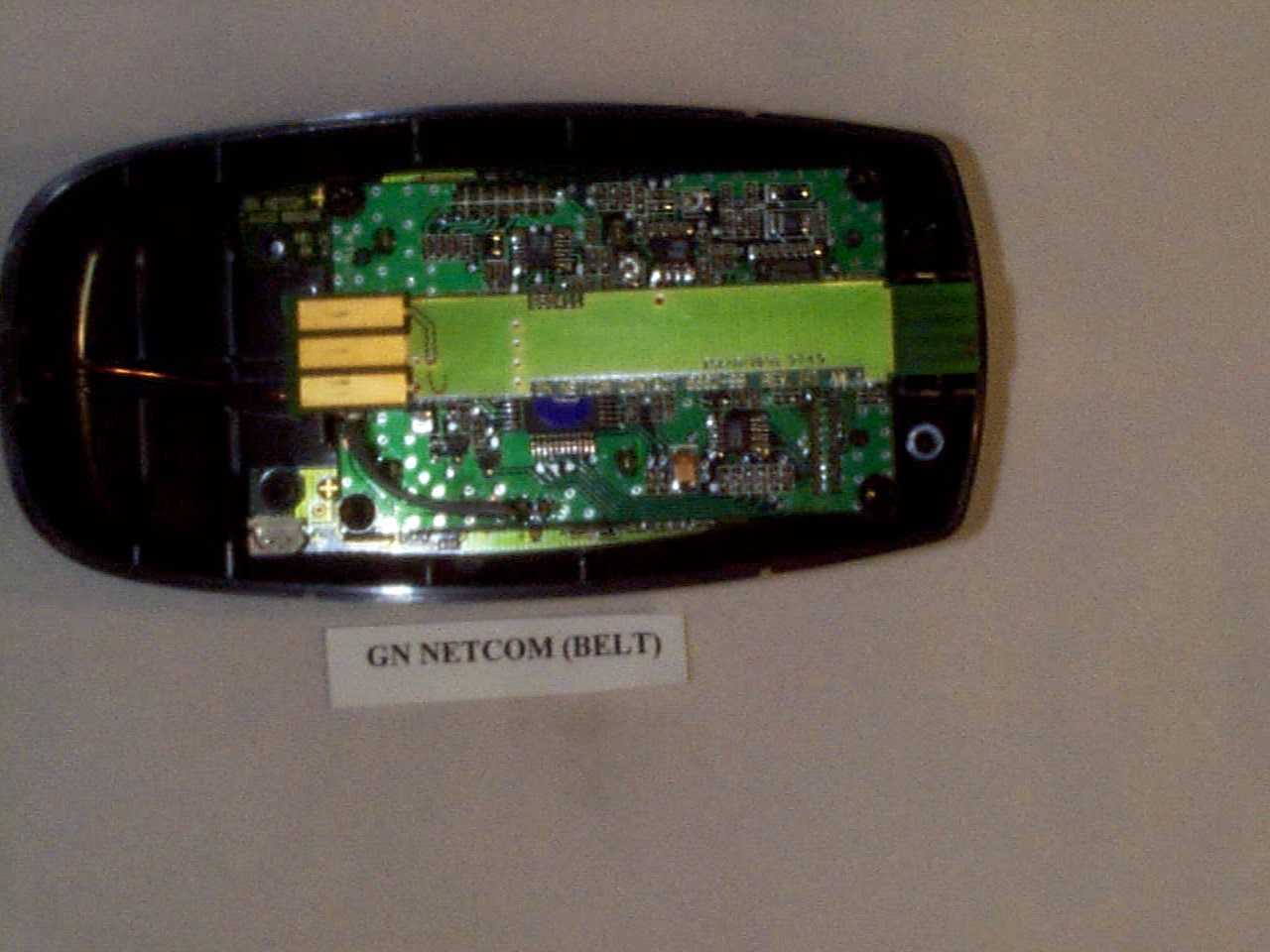
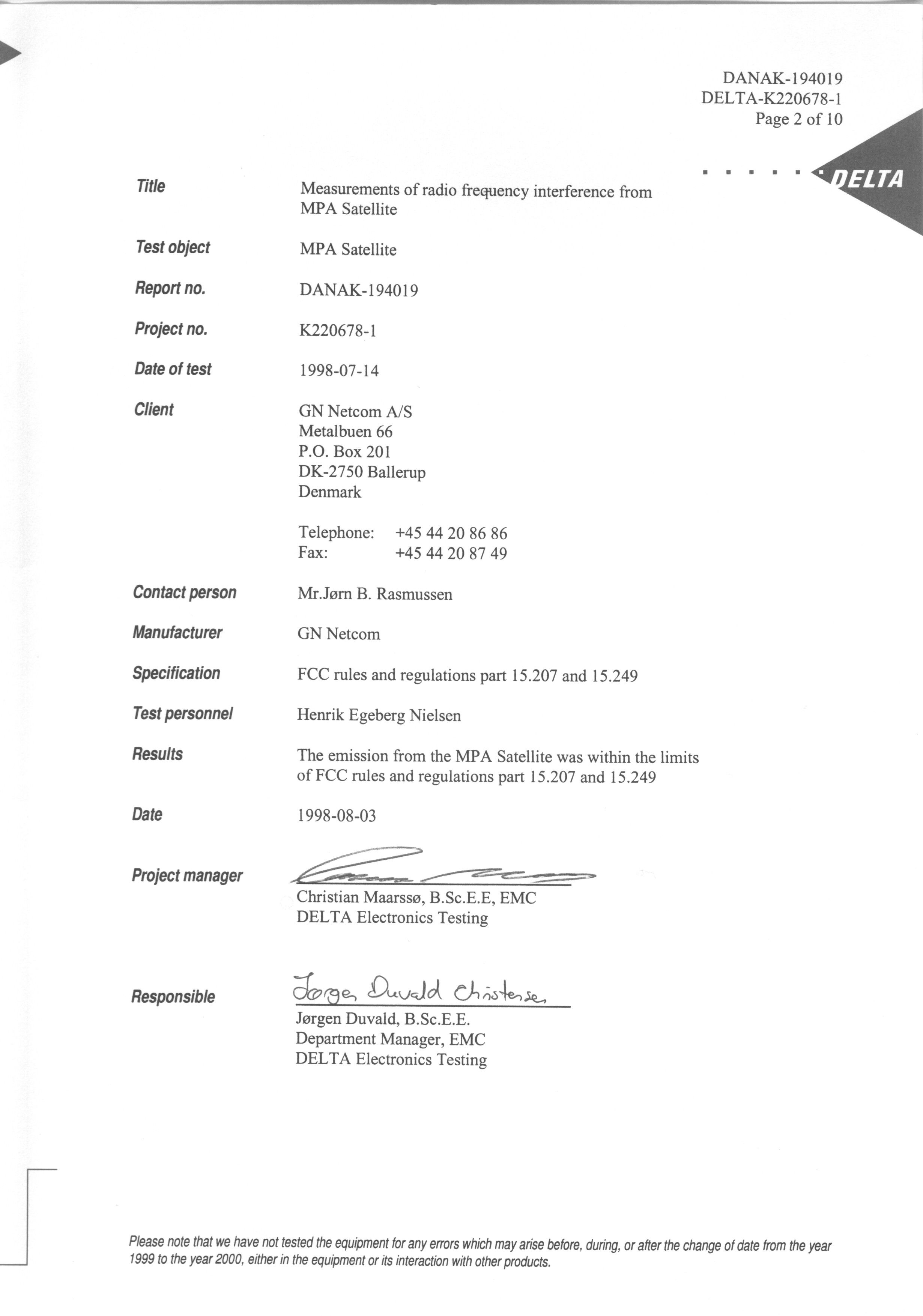
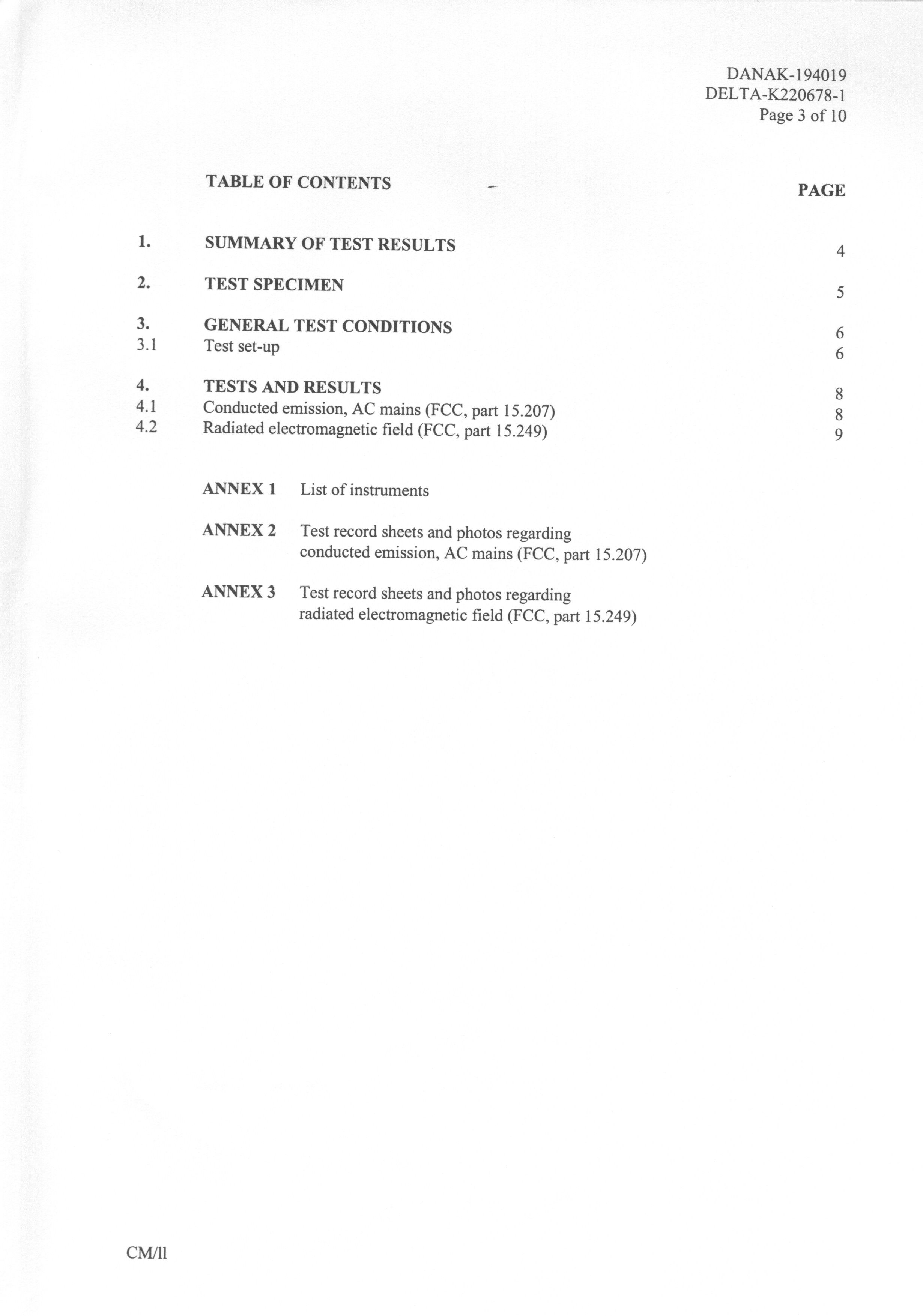
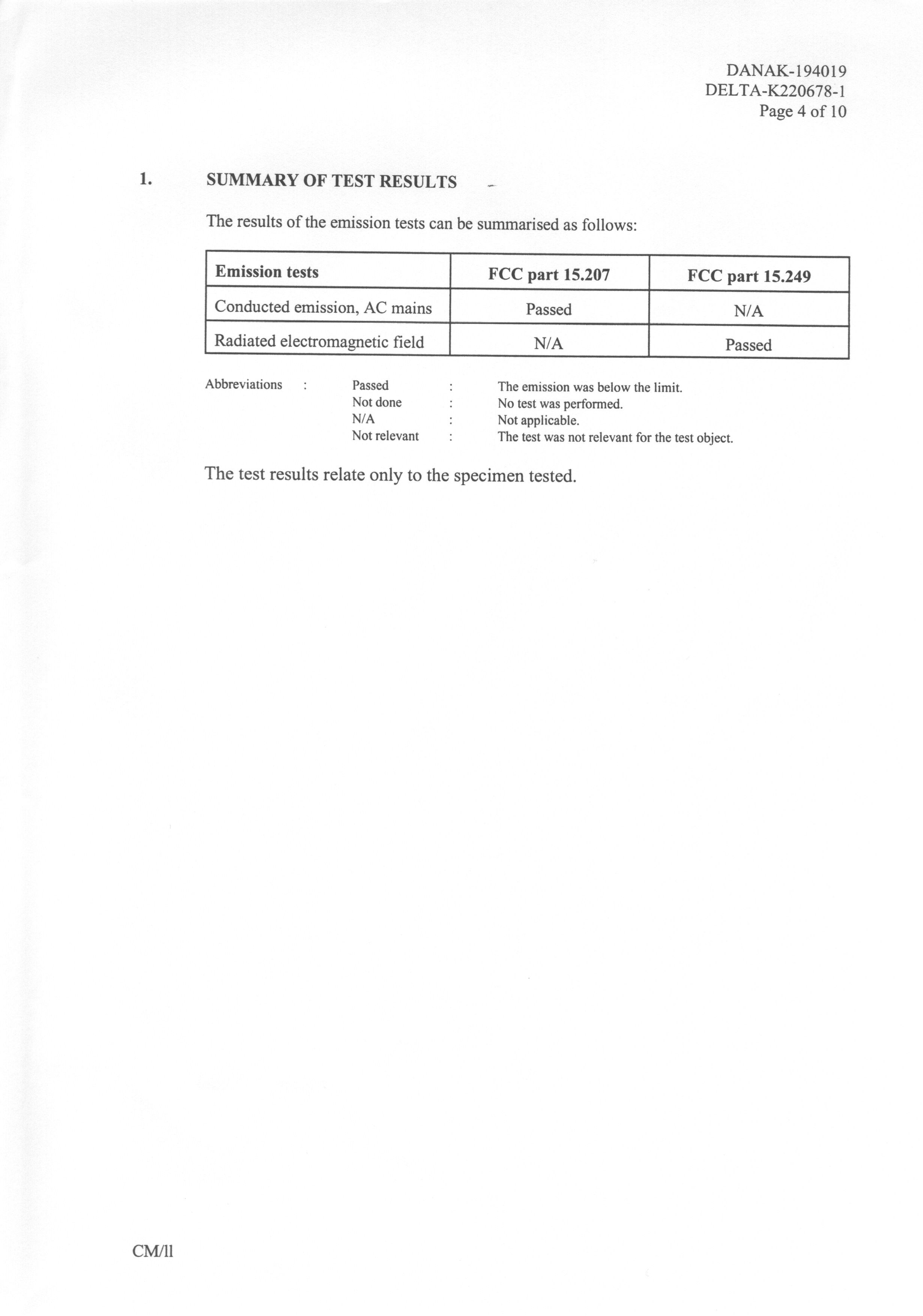
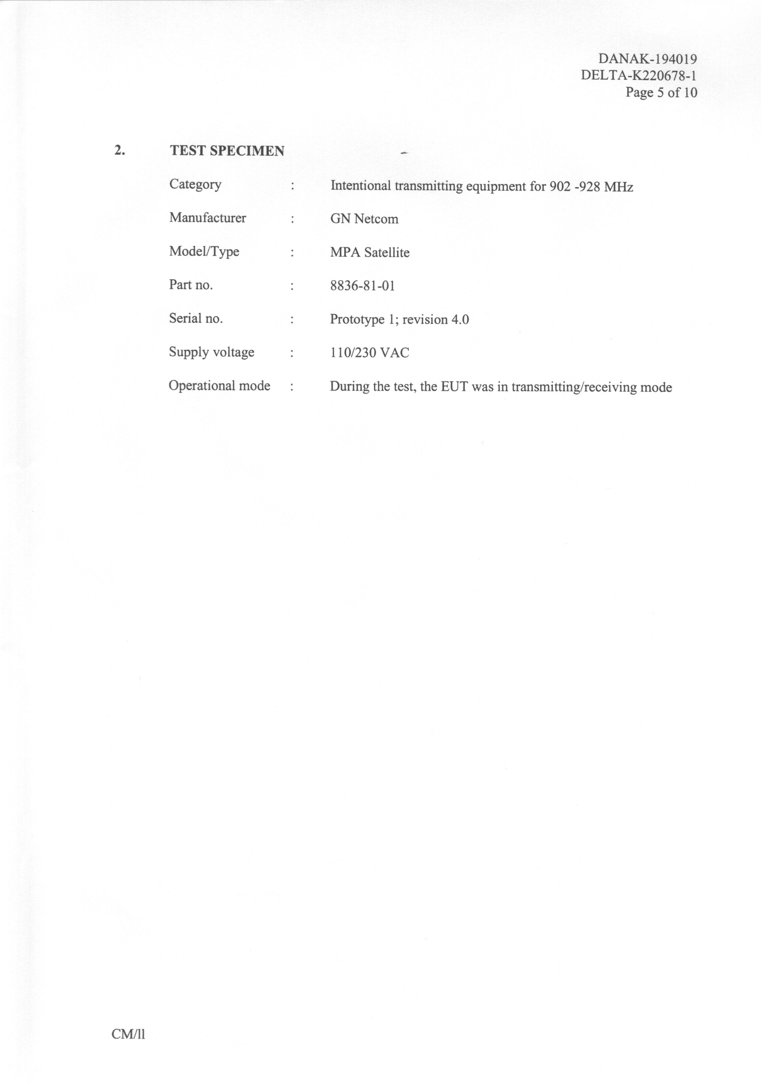



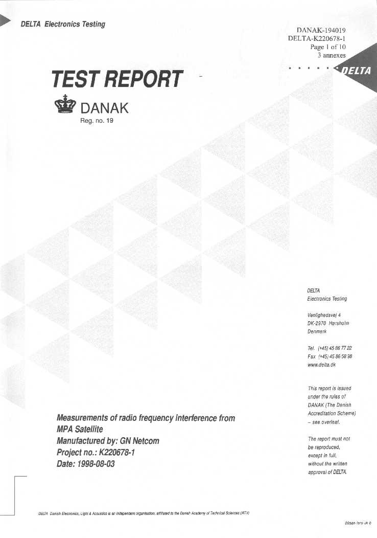
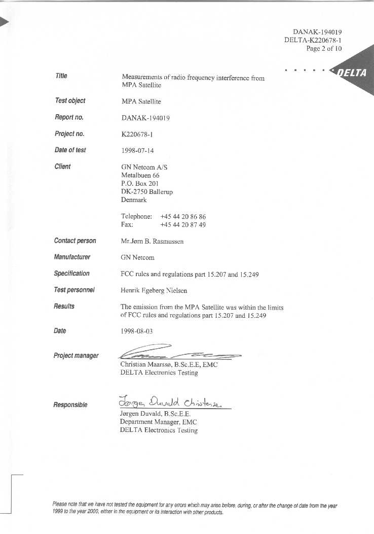
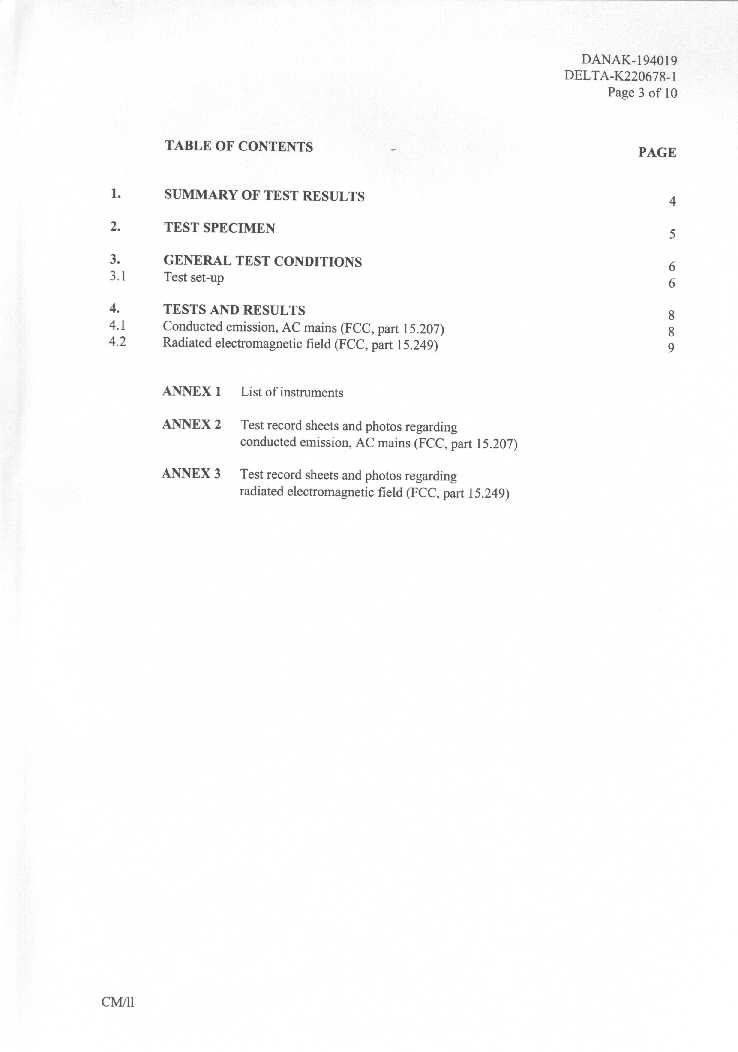
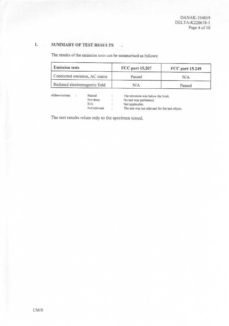
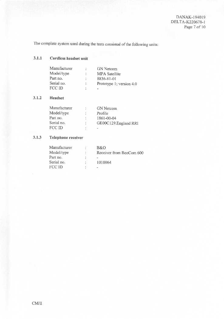
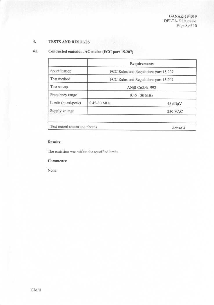
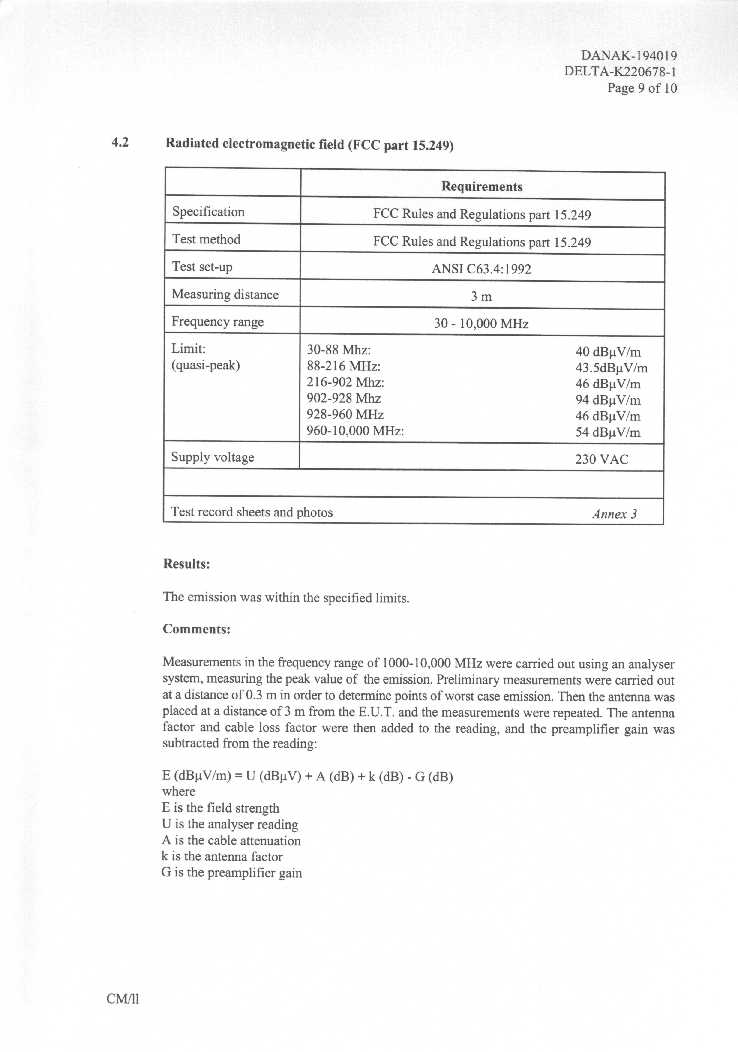



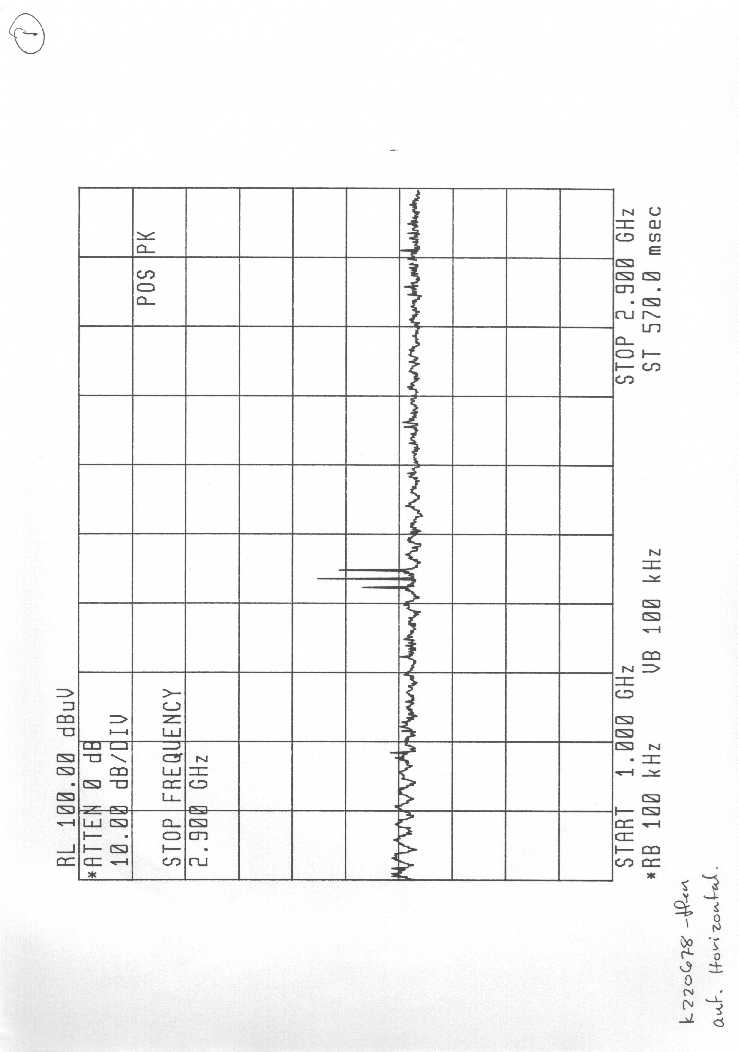
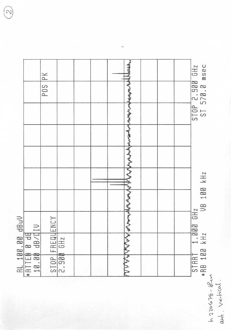

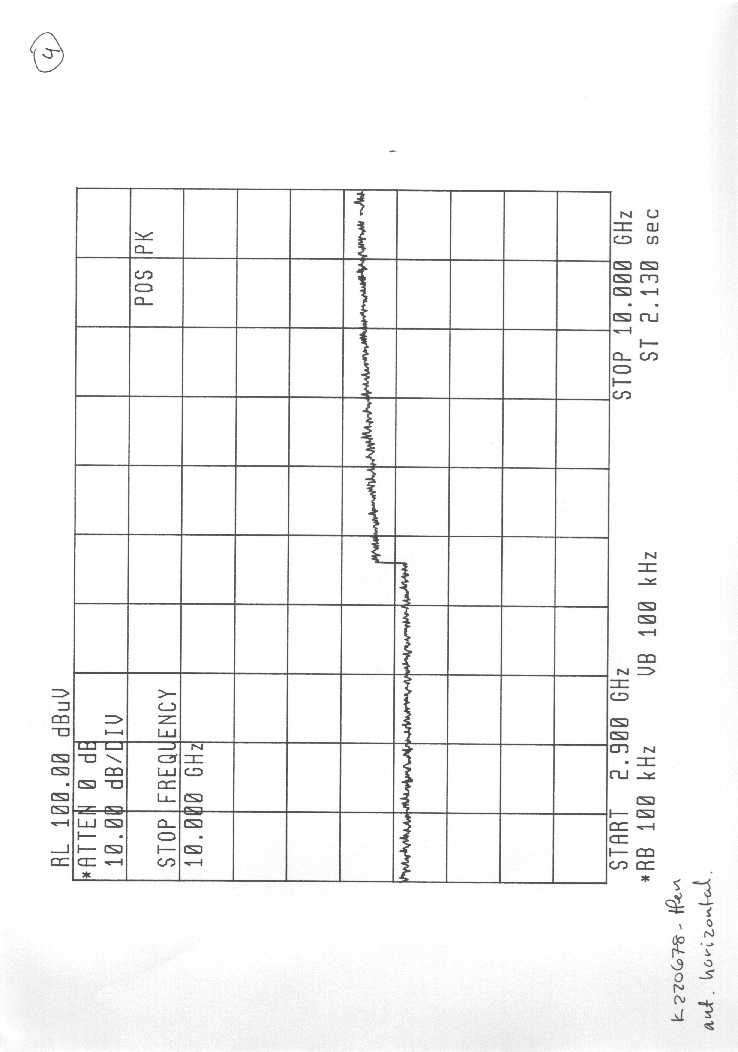
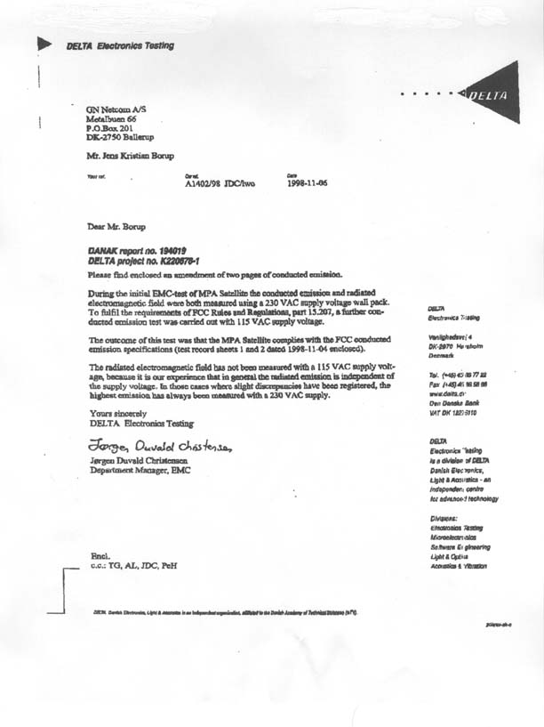
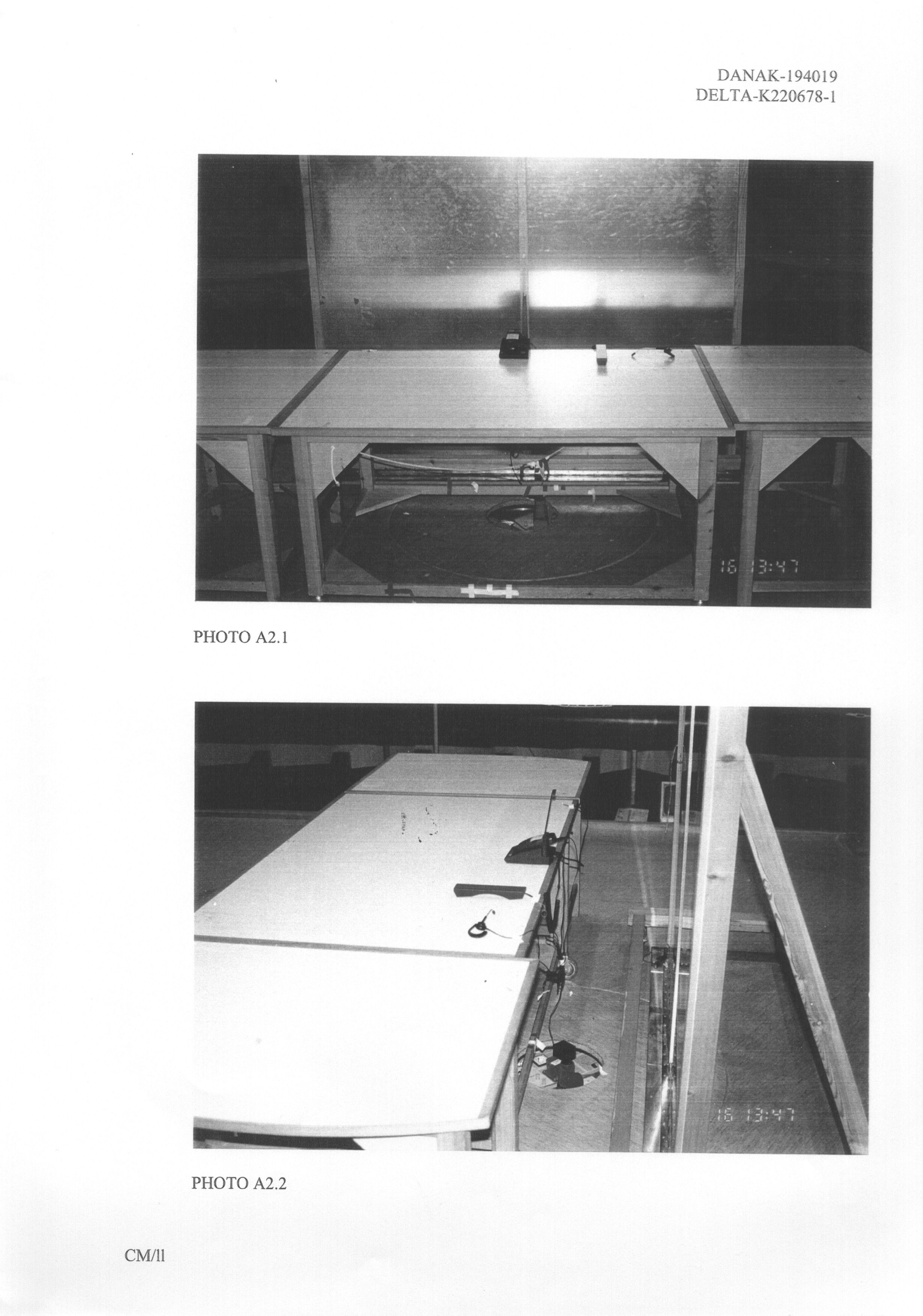
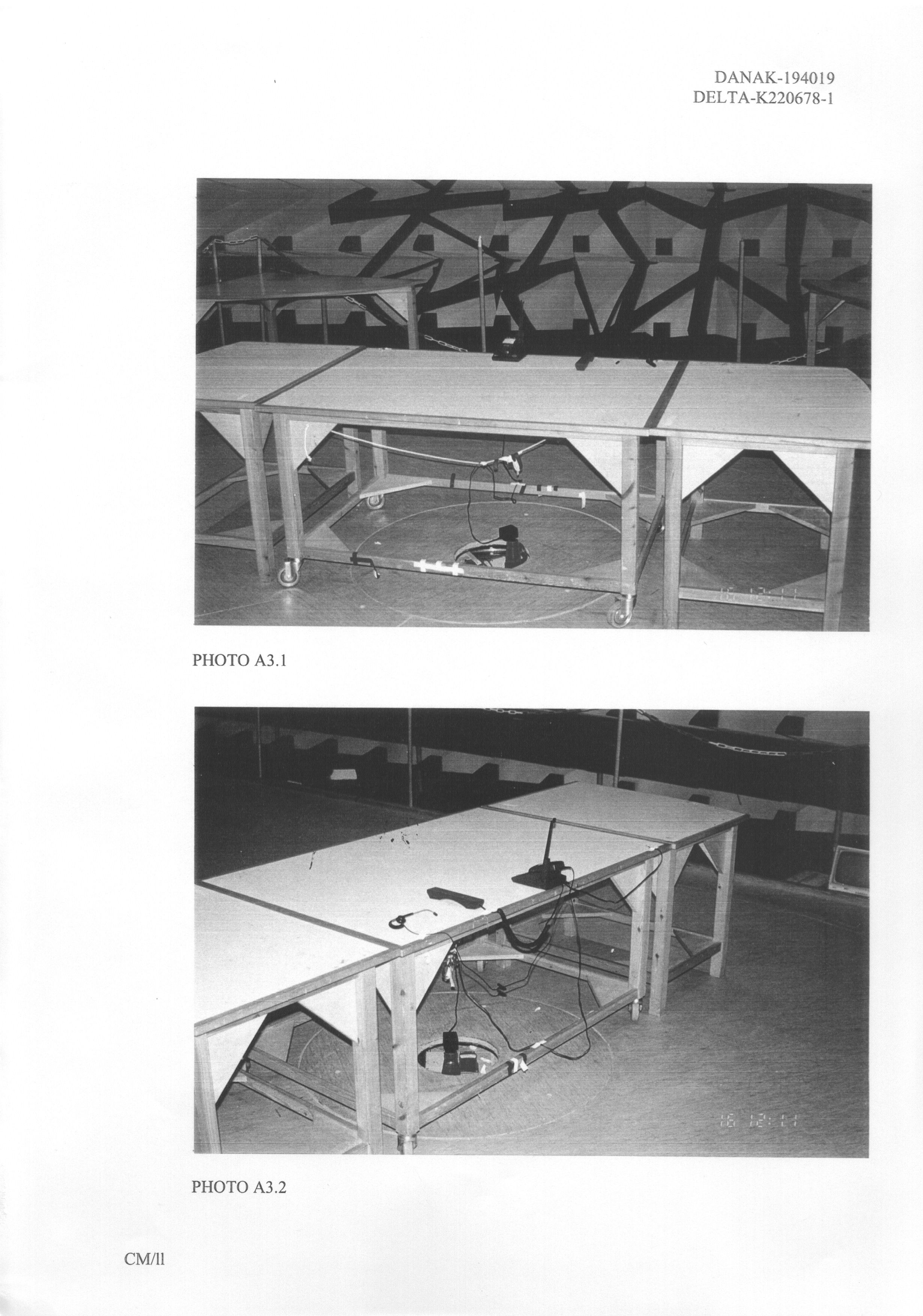
Document Text
Text extracted from the exhibit documents filed with the FCC. Open a document above to read the original.
Cover Letter(s)
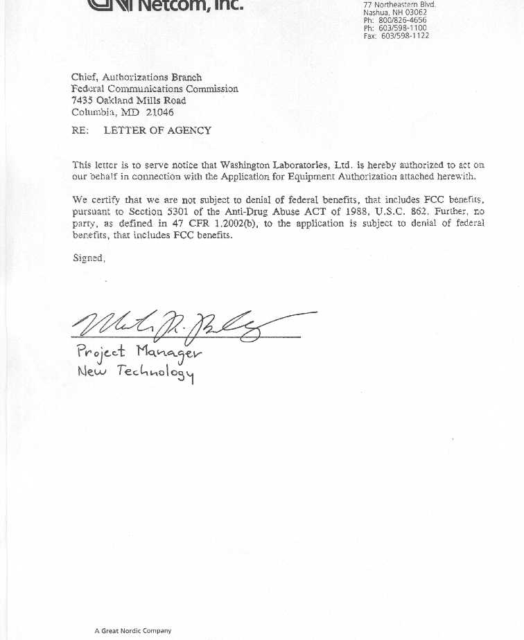
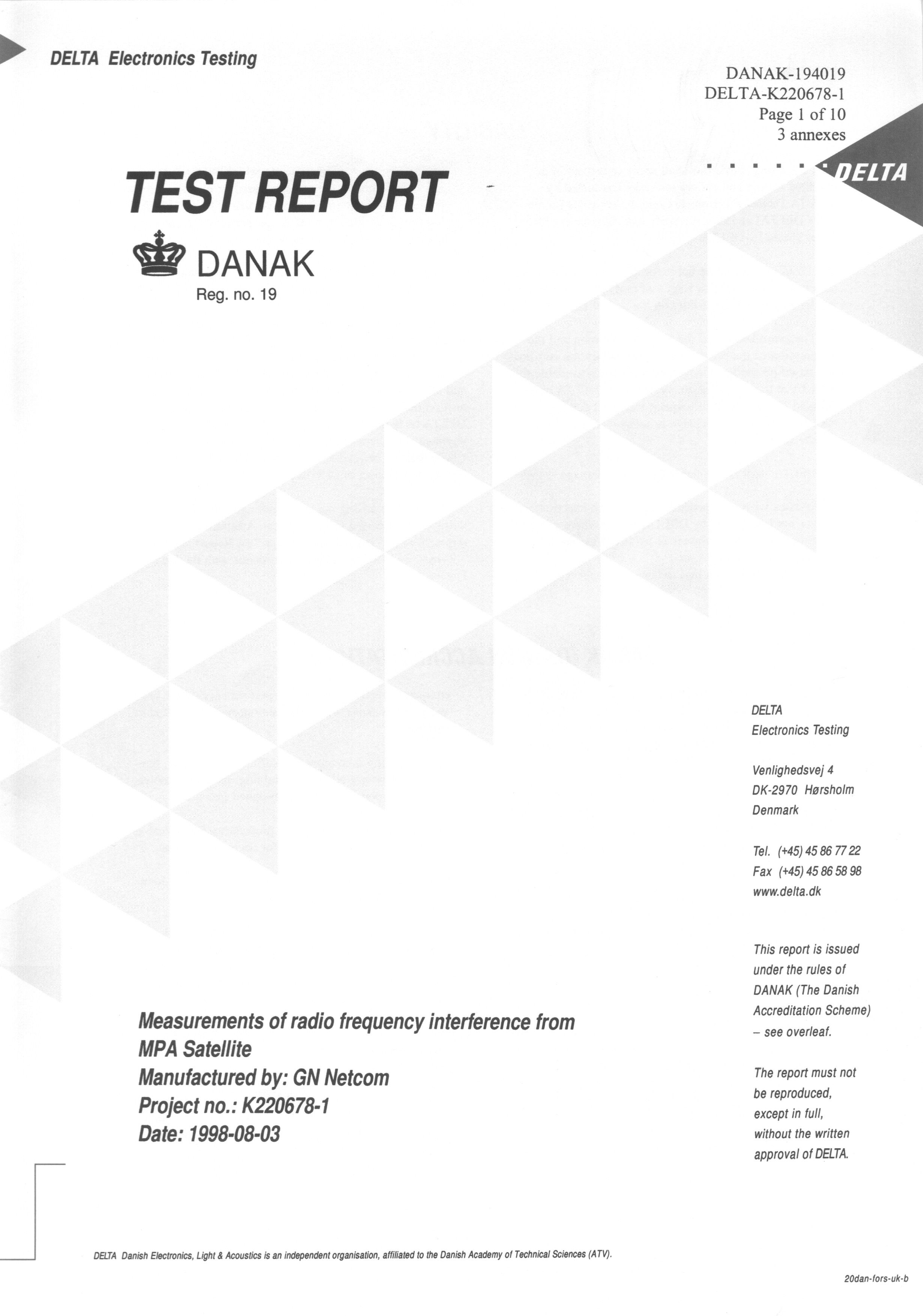
September 27, 1998 Federal Communications Commissions 7435 Oakland Mills Road Columbia, MD 21046 FCC ID: BCE-SAT-REM To Whom It May Concern: Please be advised of two issues related to the electronic filing Washington Laboratories, Ltd. is performing on behalf of our client, GN Netcom, Inc. For the purposes of the 731 form, item #16 should read as follows: Delta Electronics Testing Venlighedsvej 4 DK-2970 Horsholm Denmark Item #16 of the 731 form provided for electronic filing would not allow for input other than Washington Laboratories, Ltd. Secondly, a change of address for the Grantee Code BCE was faxed and mailed to the attention of Mary Ann Bosley on Thursday, September 24, 1998. Old AddressNew Address GN Netcom, Inc.GN Netcom, Inc. Components Division 7688 Executive Drive77 Northeastern Blvd. Eden Prairie, MN 55344Nashua, NH 03062 Should you have any questions or concerns regarding these matters, please do not hesitate to contact me at 301/417-0220. Sincerely, Ann S. Miller Engineering Assistant Washington Laboratories, Ltd.
Operational Description
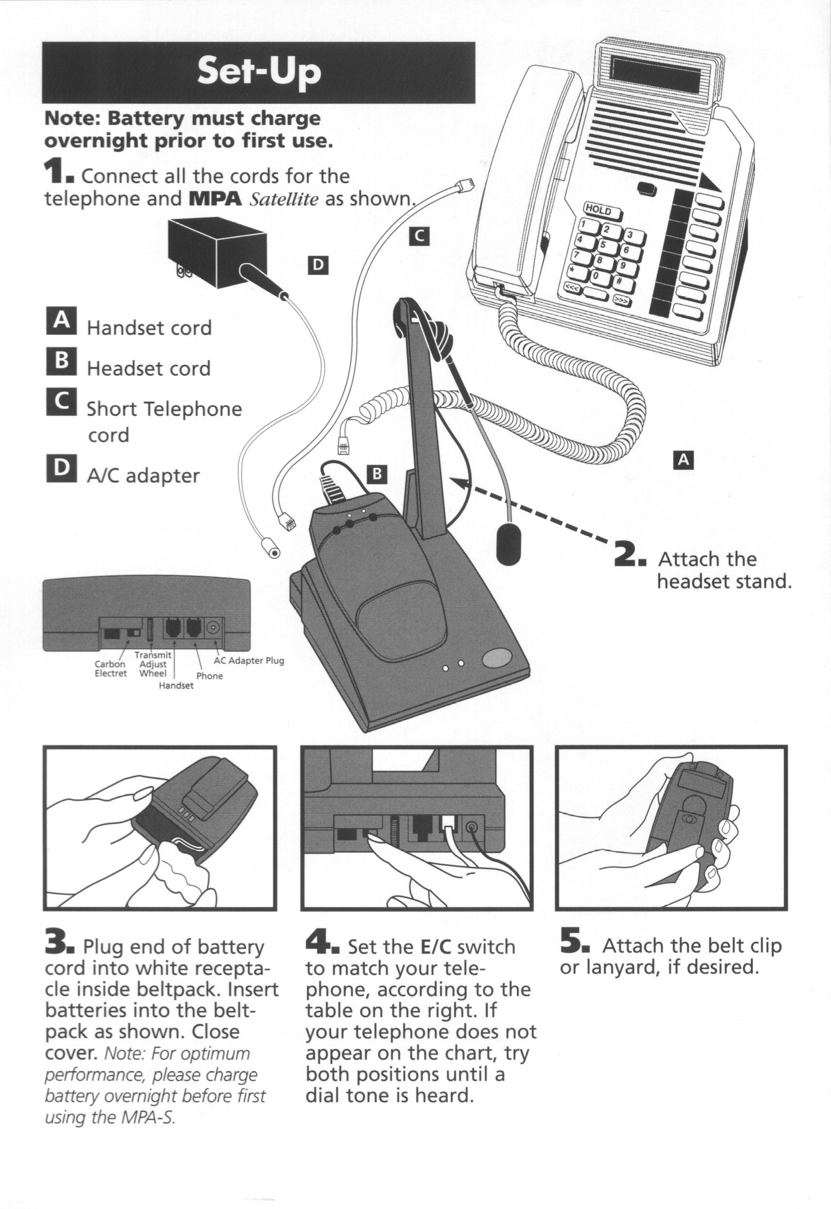
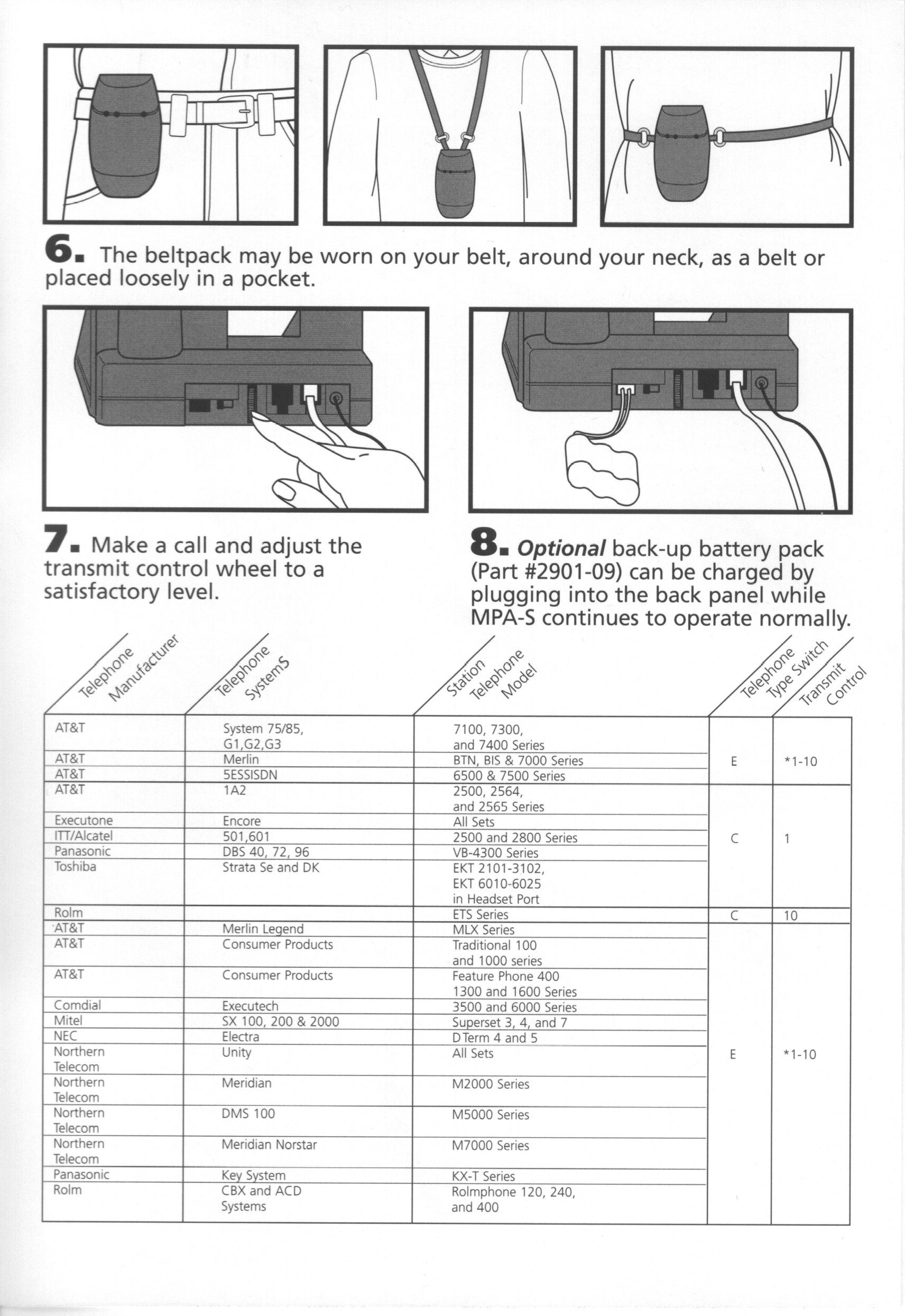
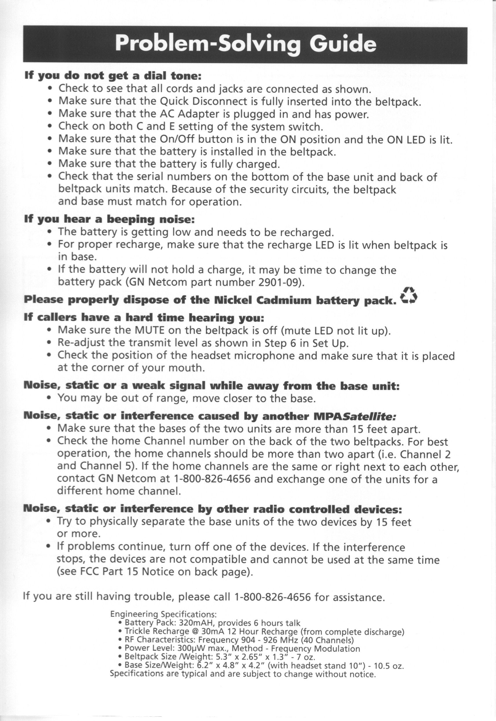
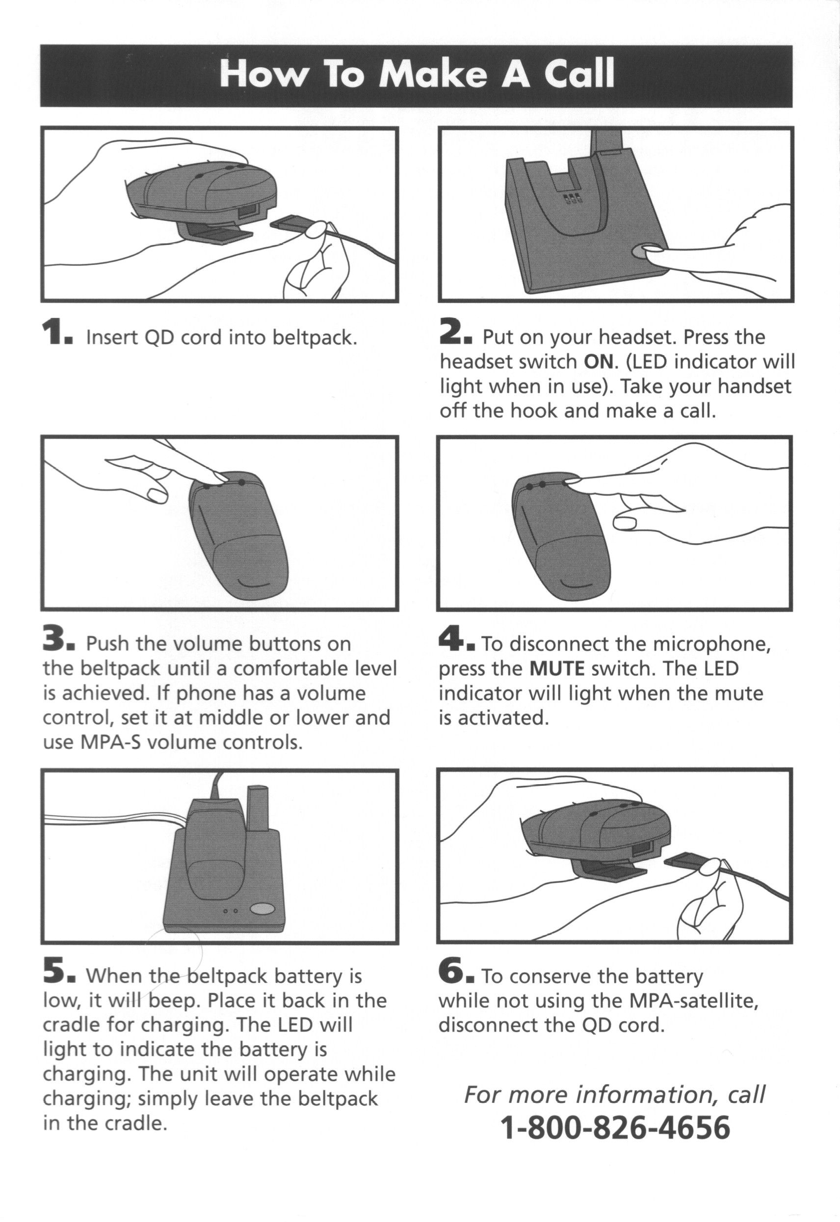
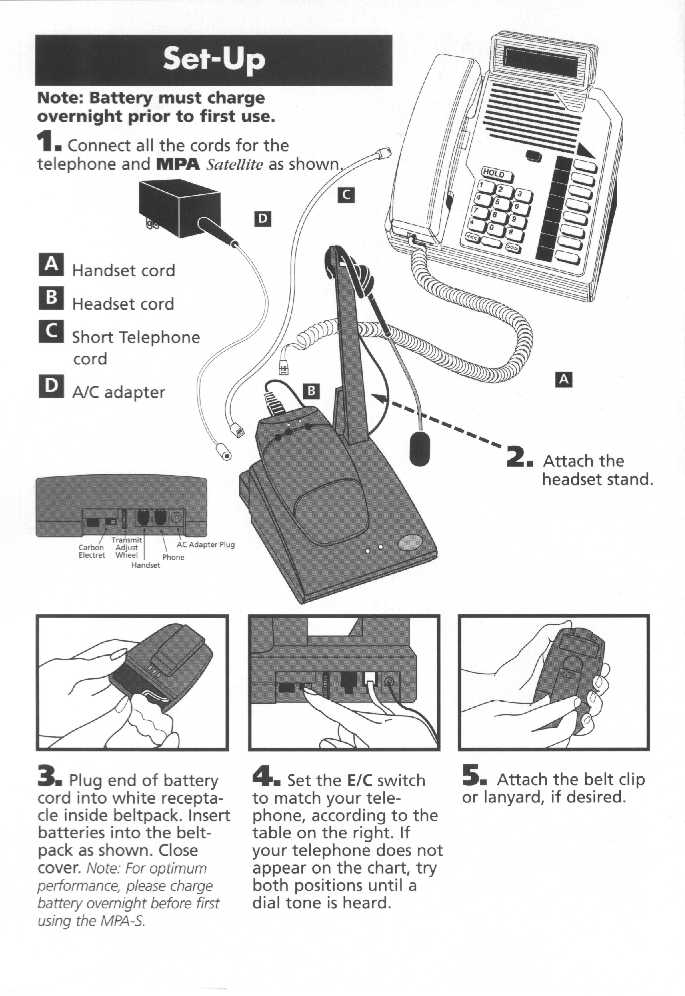
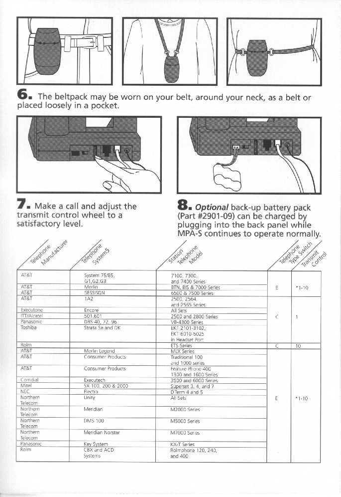
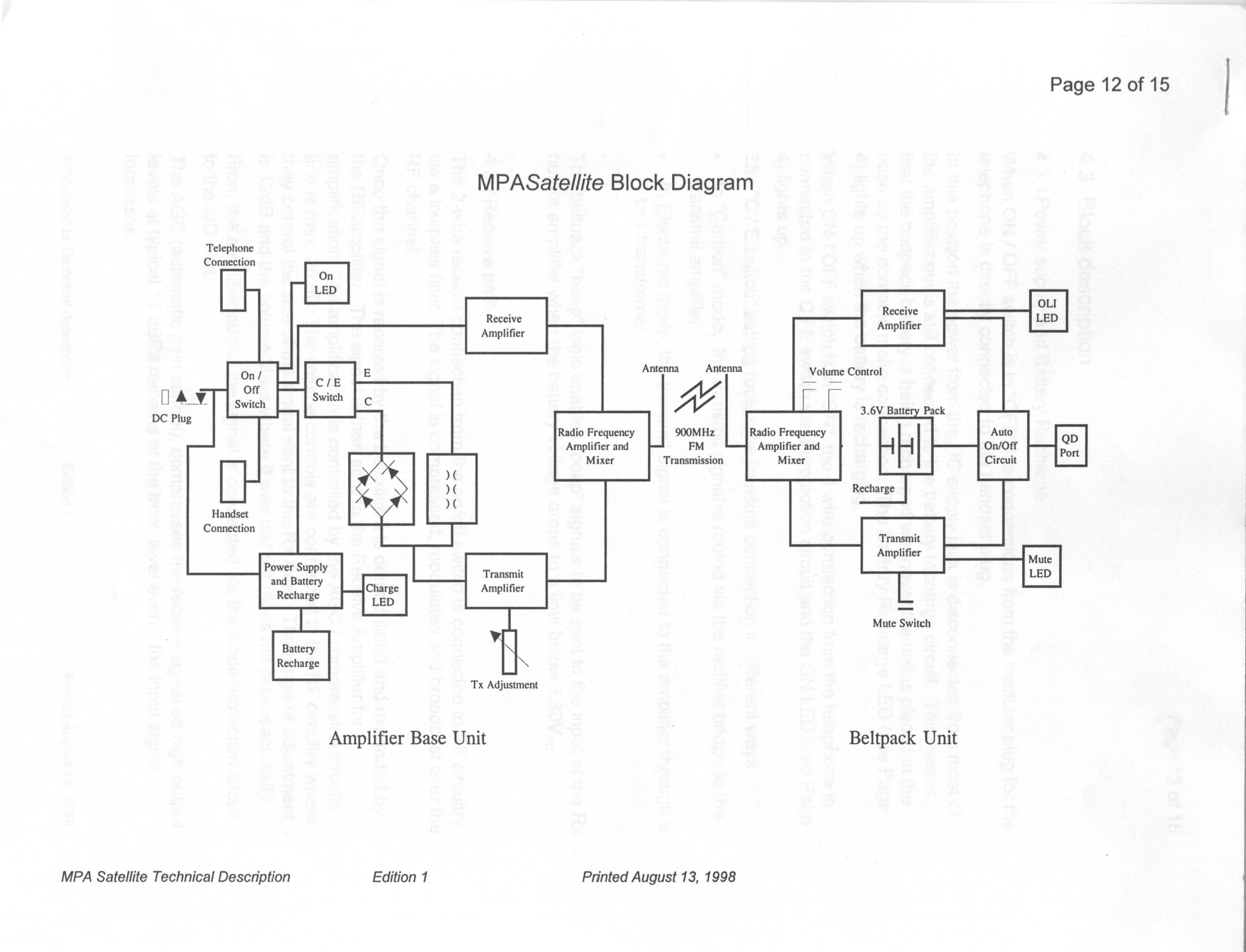
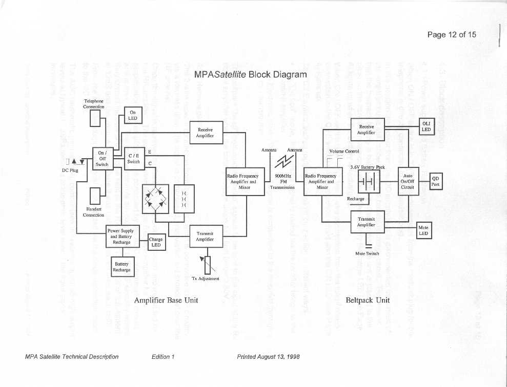
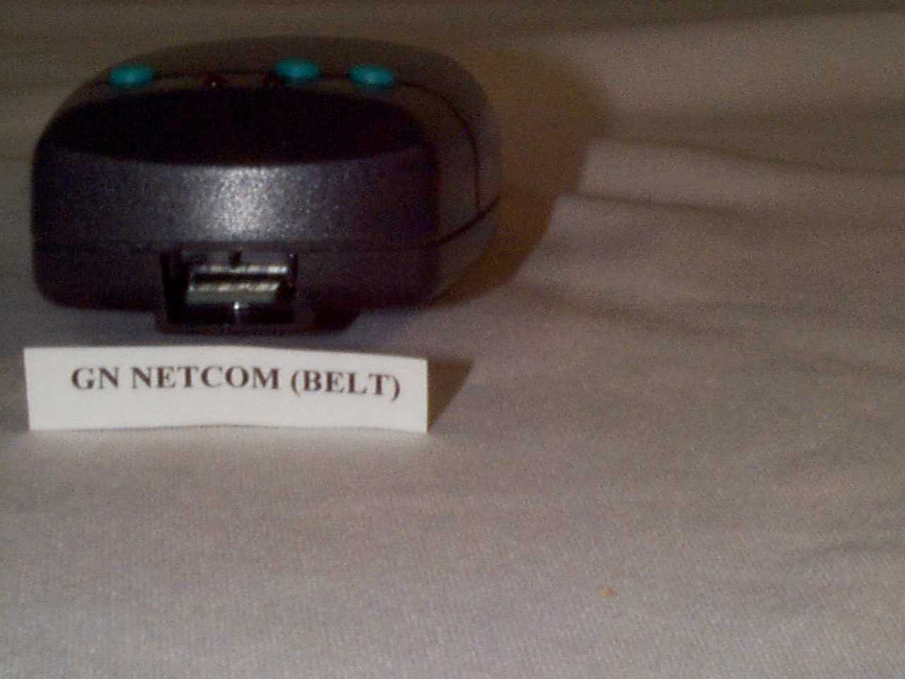
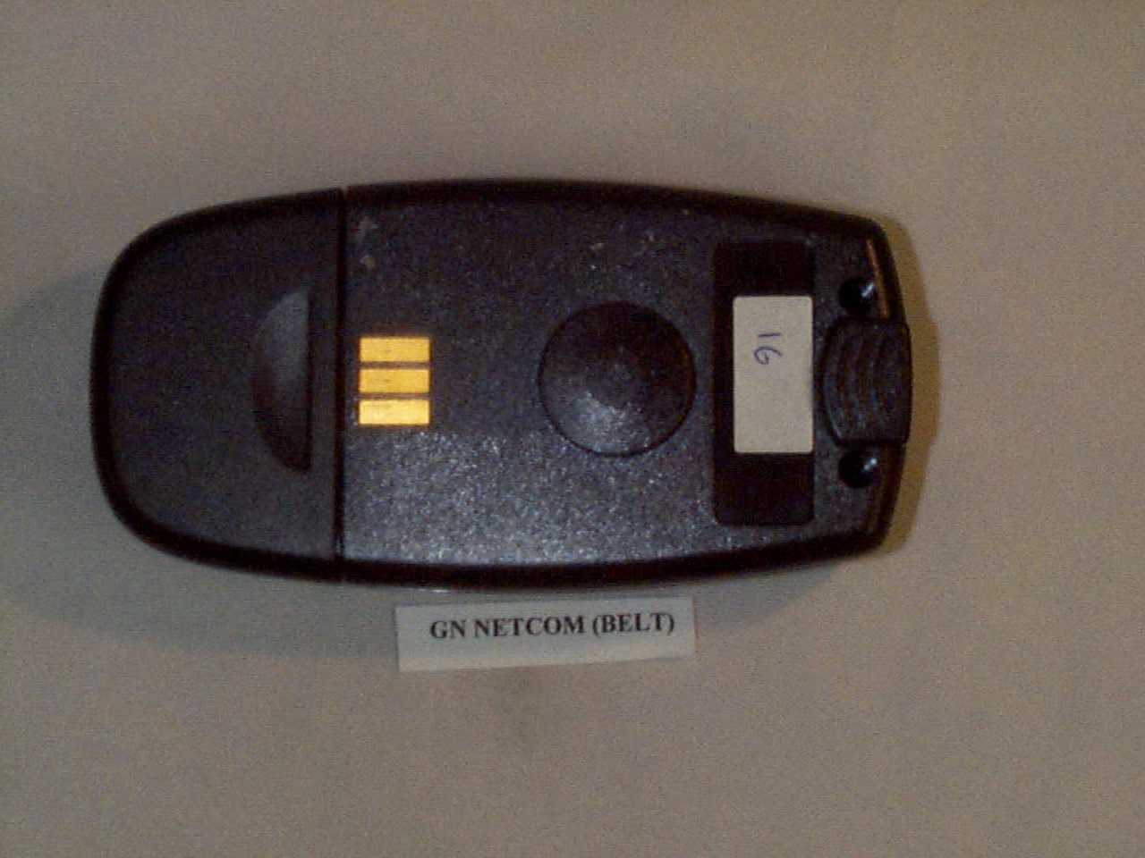
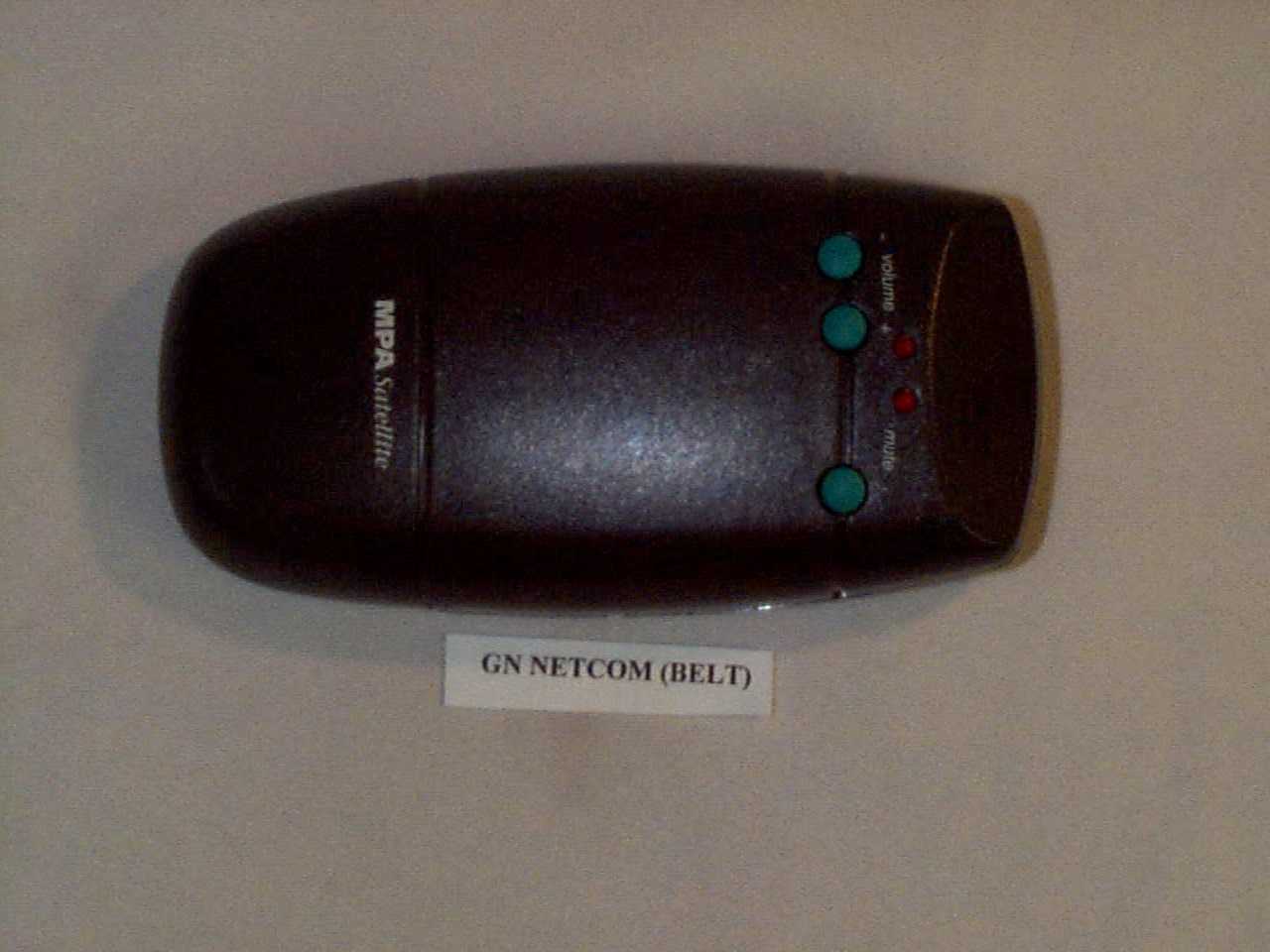
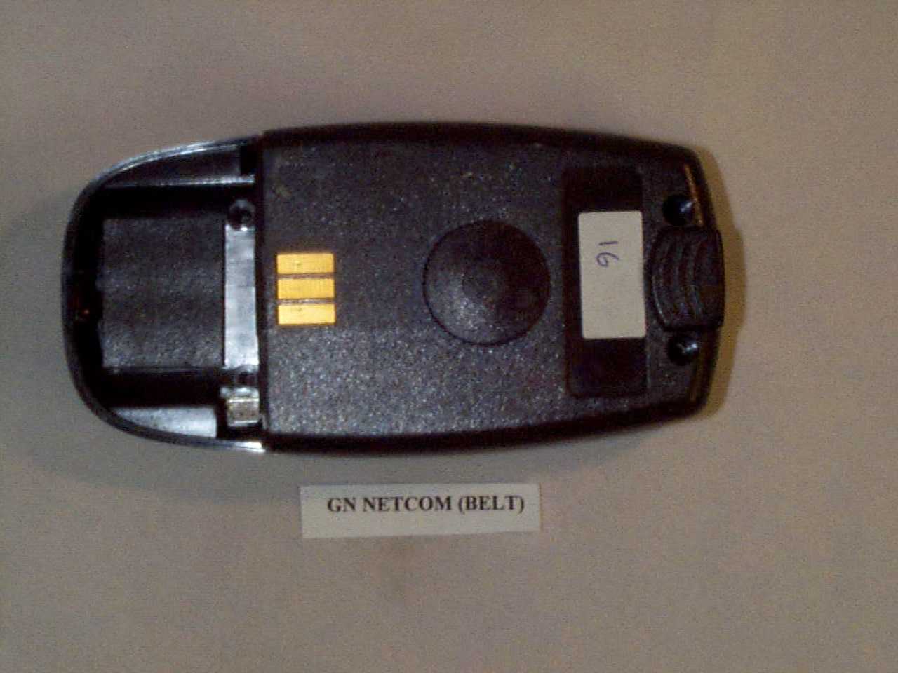
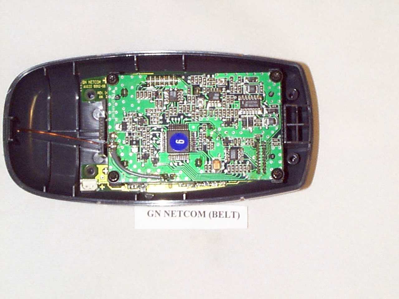
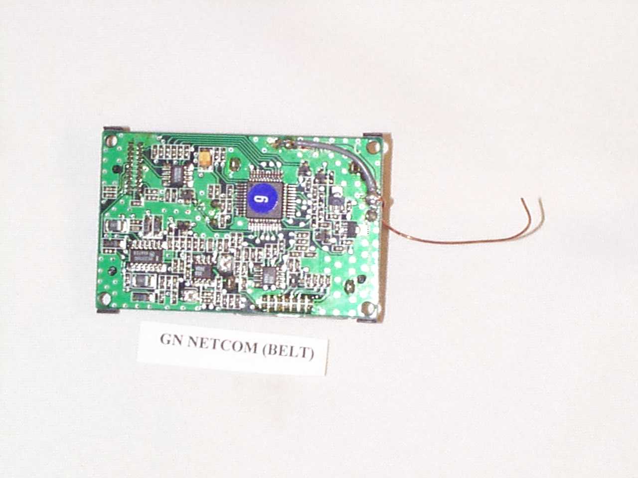
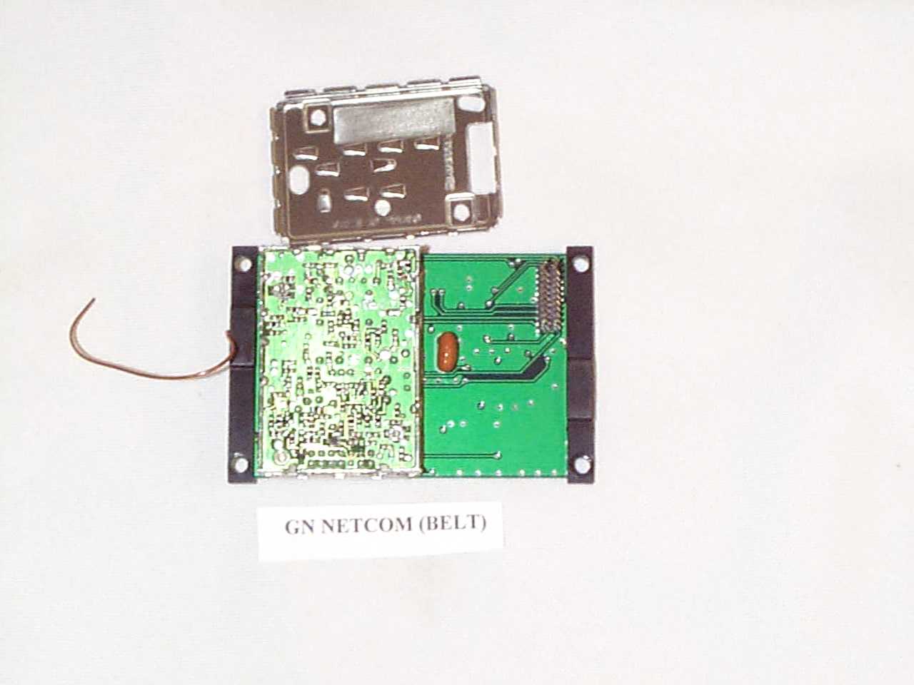
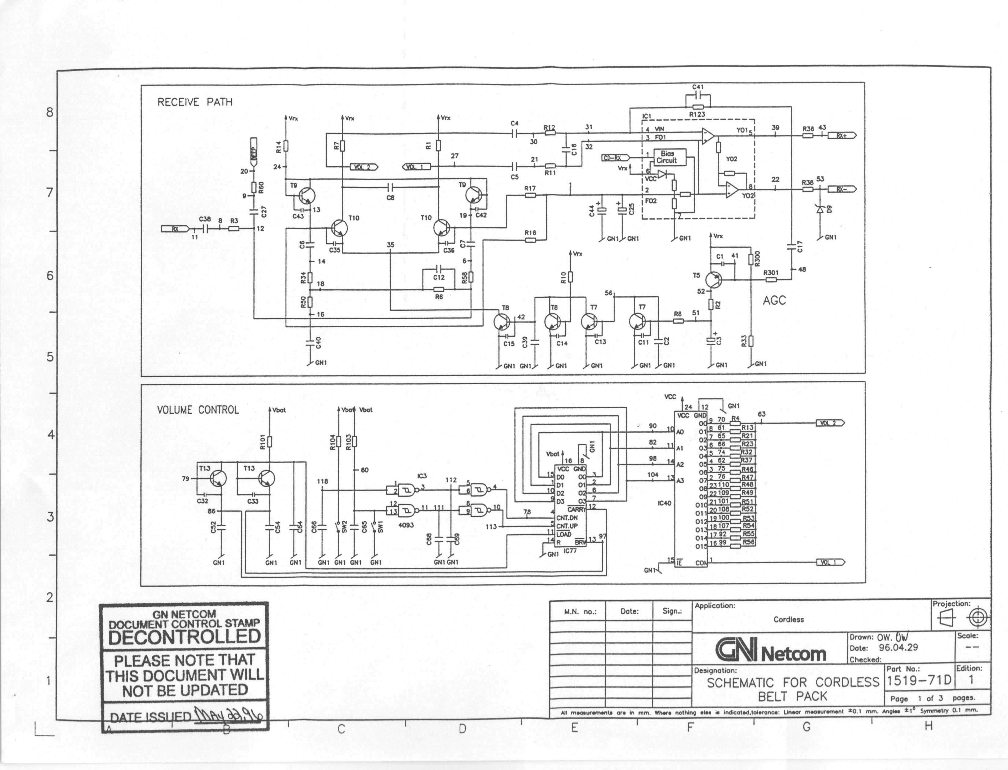
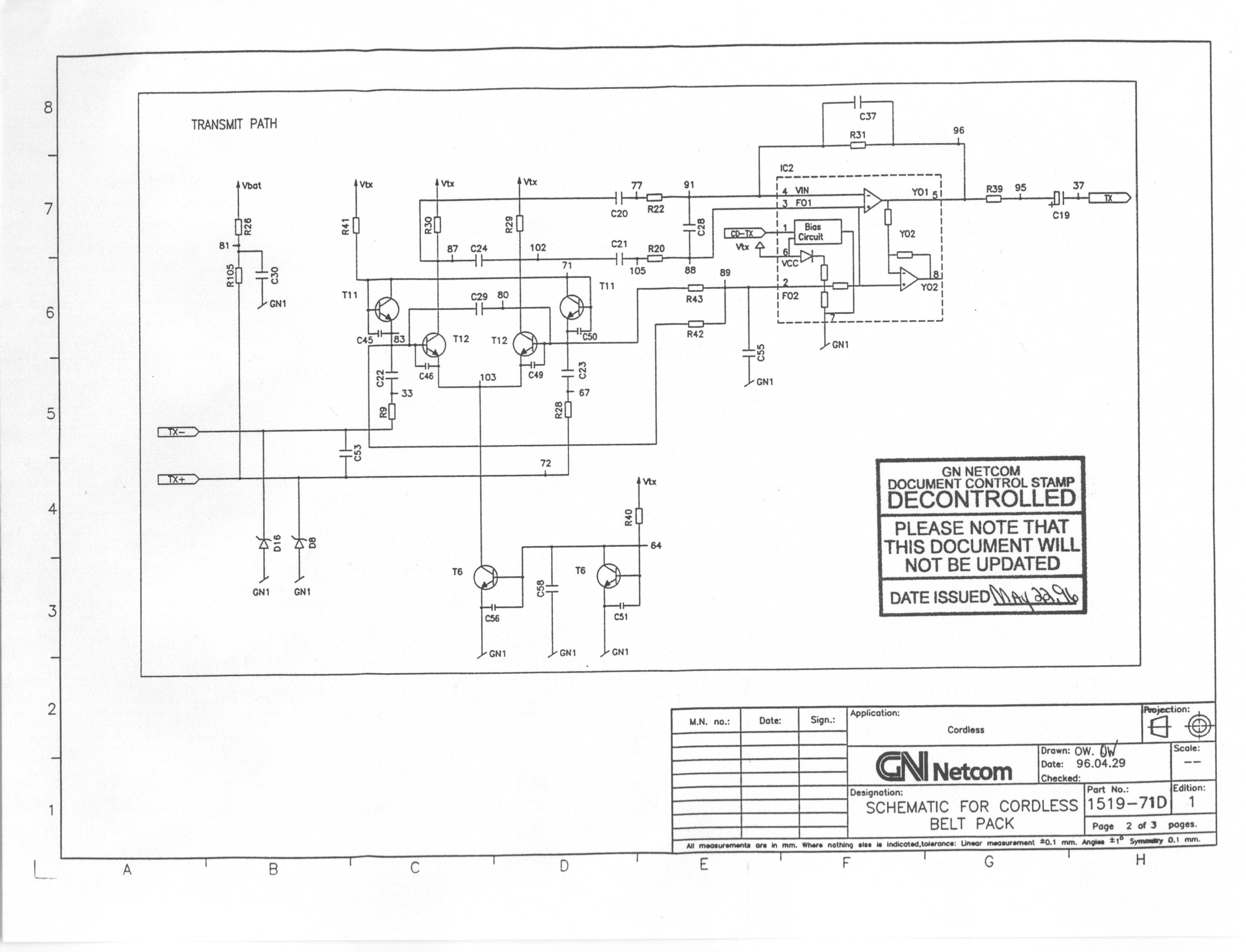
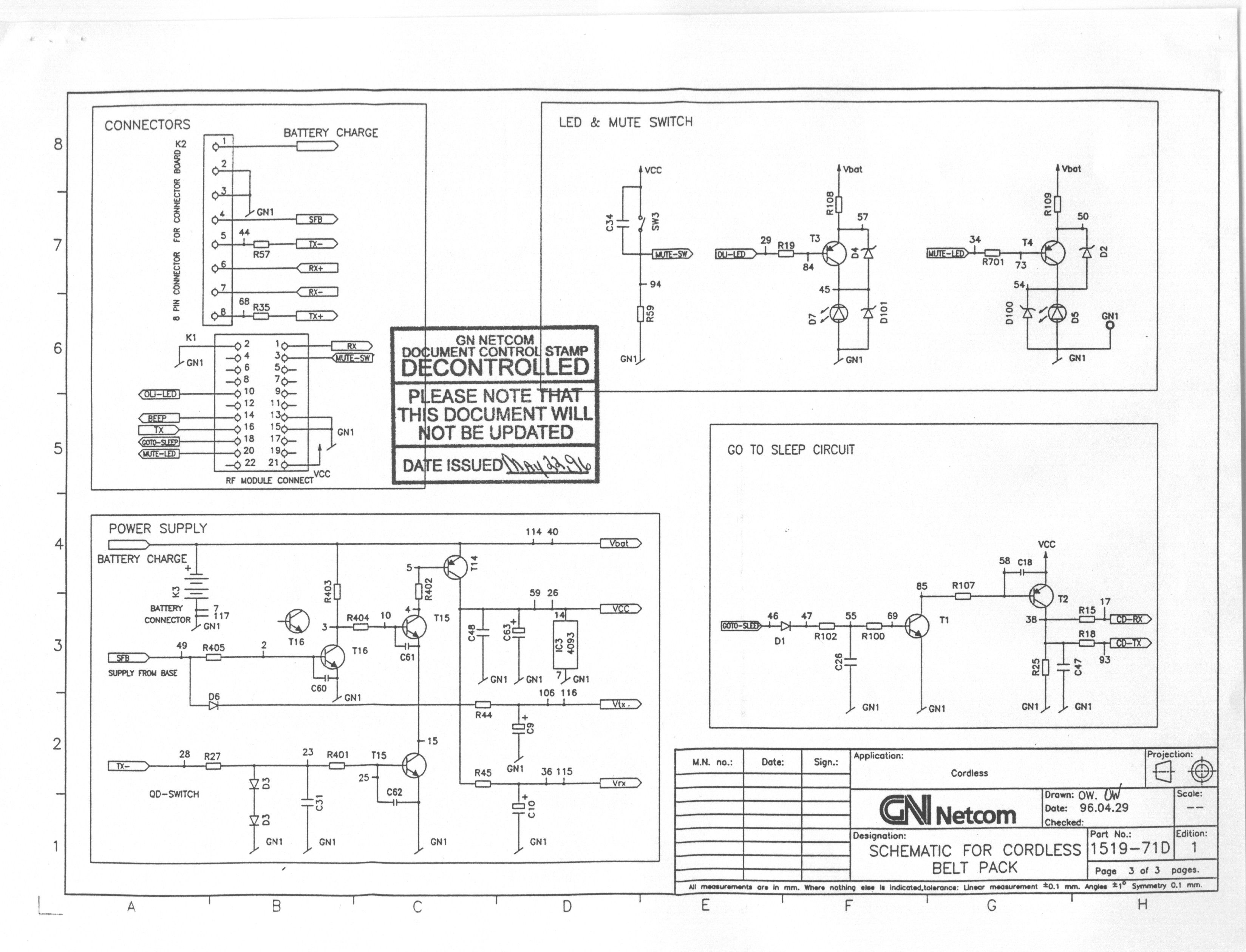
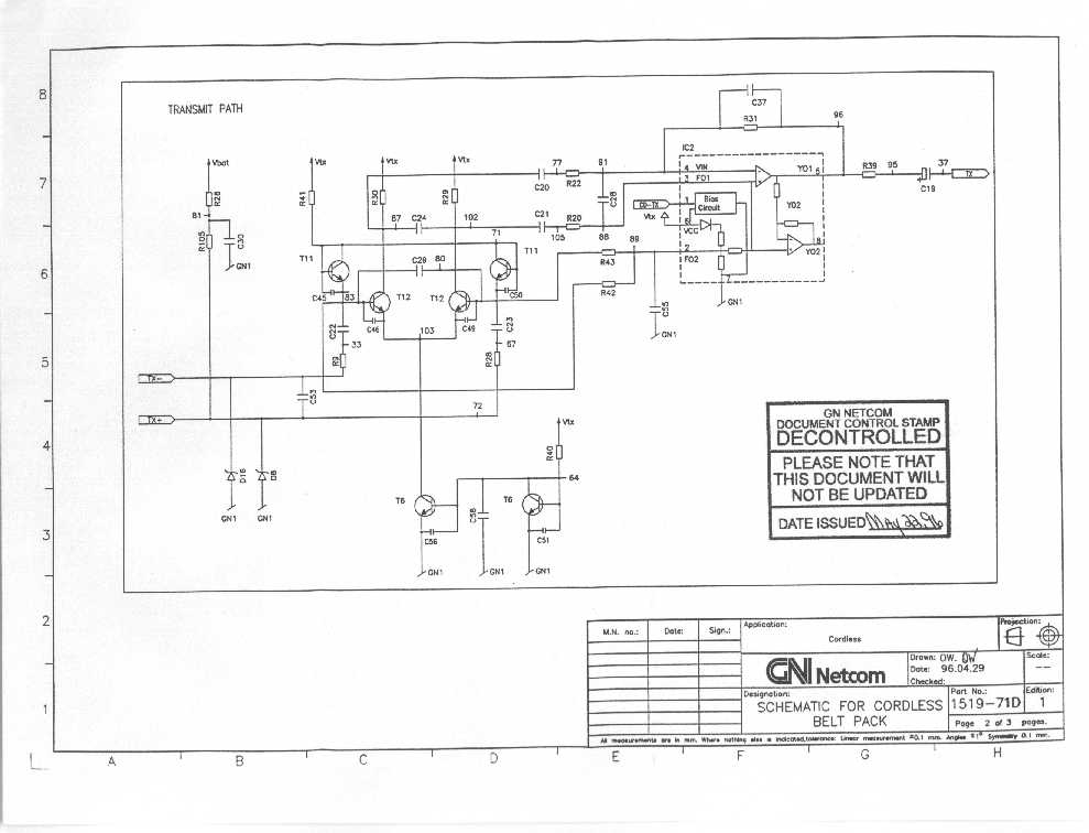
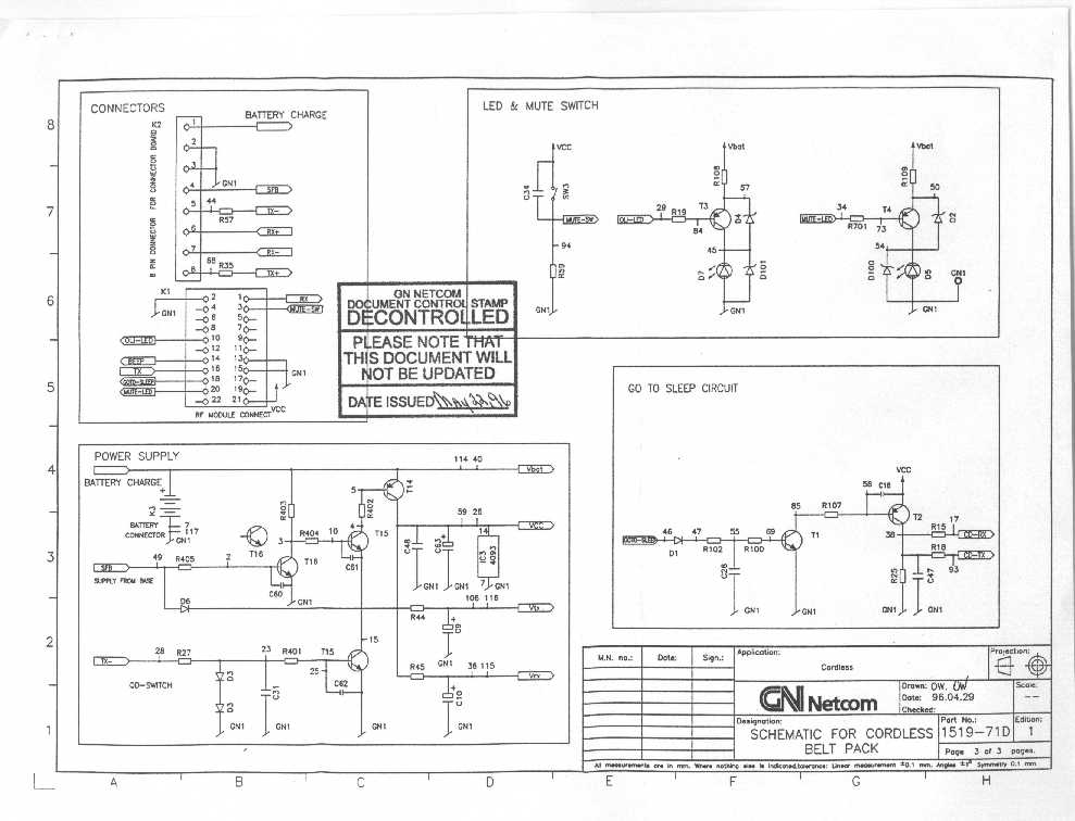
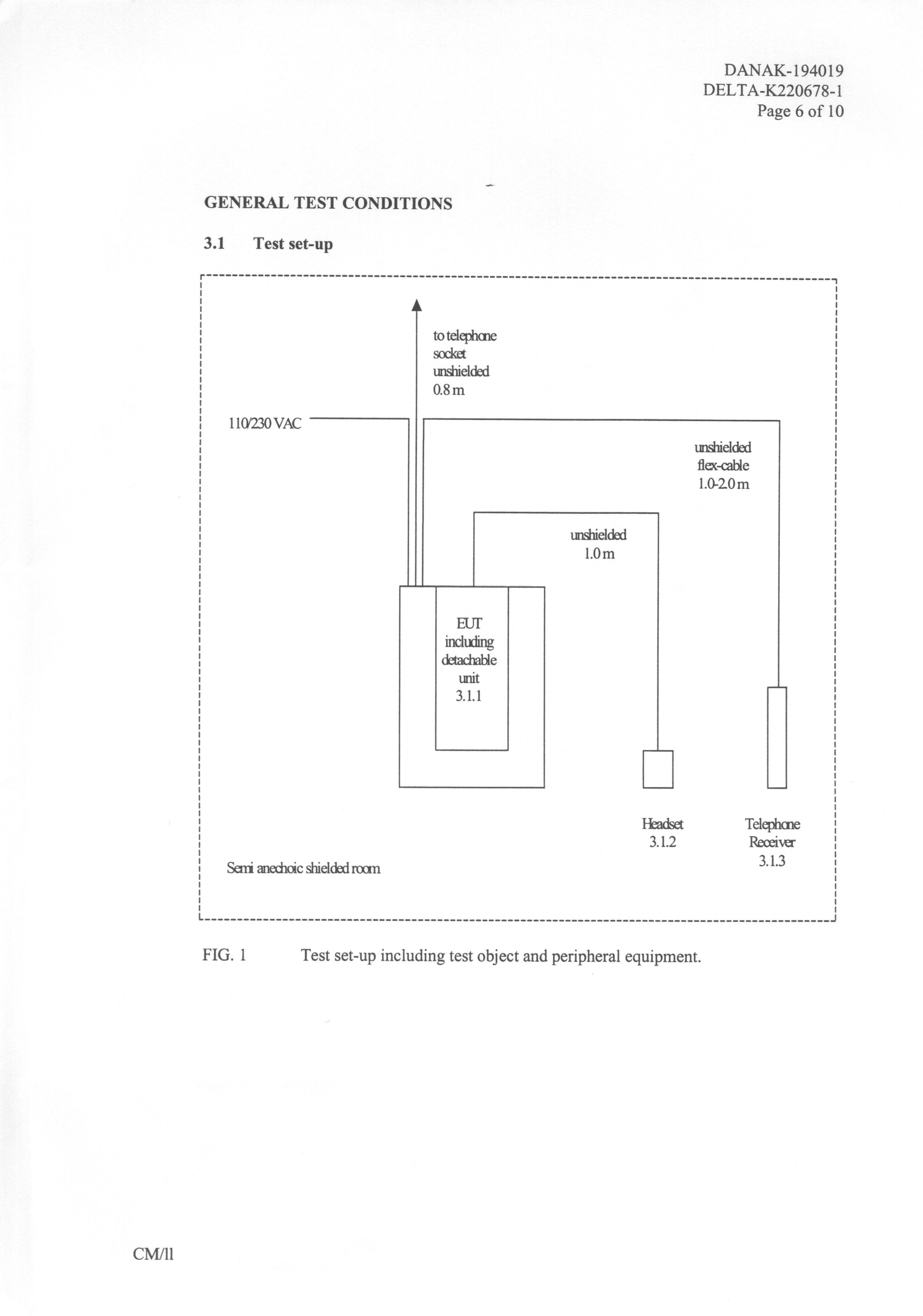
Operational Description Power Supply and Battery Recharge When On/Off switch is in “Off” the connections from the modular plug for the telephone is directly connected the handset plug. In this position the power from the DC supply jack is disconnected from most of the amplifier but is still connected to the battery recharge circuit. This means that the beltpack battery is being recharged whenever the unit is placed in the base so the contacts make connection. The Battery Recharge LED lights up when the battery is recharging. When On/Off switch is in “On”, the 4 wire connection from the telephone is connected to the C / E switch via a protection circuit and the ON LED lights up. The “C / E switch” setting routes the transmit connection in different ways. • In “Carbon” mode, the transmit signal is routed via the rectifier bridge to the transmit amplifier. • In “Electronic” mode, the transmit signal is connected to the amplifier through a 1 to 1 transformer. The beltpack “beep” logic enables “beep” signals to be sent to the input of the Rx output amplifier when the battery voltage drops to a limit below 3.30V DC. Receive Path The 2-wire receive connections from the on/off switch is connected to RF circuitry via a lowpass filter. The signal is compressed, modulated and broadcast over the RF channel. Once the signal is received by the beltpack it is demodulated and expanded by the RF amplifier. The signal is then sent to the Receive Amplifier for amplification. The amplification is controlled by the AGC / compression circuits and is max. 20dB. The volume controls are connected to the RF circuitry where they control the size of the signal sent to the Rx Amp. The range of adjustment is 12dB and the volume stays where it was last set (does not reset each call). From the amplifier output the signal is connected via the diode protection circuit to the QD port. The AGC (automatic gain control), compresses the receive signal so high output levels at typical 11 dBPa remains at the max. level even if the input signal increases. Transmit Path The headset’s electric microphone is connected via the QD Port to the input of a 2 stage transmit preamplifier. The mic. Supply voltage is applied to the “mic.+” connection. The signal is put through a buffer amplifier which can be disconnected by the Mute switch. When the mute is pressed on (no transmission) the mute LED is lit and the mute stays on until the button is pressed again. The signal is then compressed, filtered, modulated and broadcast over the RF channel. Once the signal is received by the base unit, the signal is demodulated, filtered, expanded and sent to the Transmit Amplifier. The gain in the transmit preamplifier is current controlled. The first stage is controlled by the squelch and the transmit AGC circuits, the second stage is controlled by the circuit that limits the output level to fit to the specifications of the 2 telephone types. The output of the preamplifier is connected to the transmit potentiometer. The slider is connected to the input of the transmit output amplifier. Depending on the system type switch setting the variation area of the potentiometer is limited to 6 dB in Carbon and 40 dB in Electronic mode. After the In the transmit output amplifier the mic. Signal is amplified max. 8 dB, however, the output signal is controlled by the mute circuit to obtain a microphone mute of more than 80 dB. The output is connected to system type switch via the necessary circuits for carbon telephone connection; diode bridge, and electronic telephones: transformer to obtain galvanic isolation. Depending on the setting of the system type switch the correct circuit is connected to the On/Off switch and line plug. The squelch circuit receives the signal direct from the microphone path and decreases the output signal from the transmit amplifier when the input is below a specified level. The transmit AGC circuit controls the transmit output signal to stabilize at a given level depending on the adjustment of the Tx control when the sound pressure at the microphone is more that approx. 0 dB pa. Radio Frequency Amplifier Circuit The MPA Satellite is a full duplex radio link operating in the 900MHz range. It covers 40 channels and at the initiation of a call, a free channel is accessed and a unique ID code is transmitted to the beltpack. Only the beltpack with the matching ID code can establish a connection. To conserve power, the beltpack units have a low and high power mode. When connection is established, the beltpack starts out in low power mode. The Base unit will supervise the reception quality and the signal degrades below a specified level, the base commands the beltpack to increase the power mode. The radio link is microprocessor controlled. The processor controls: • Programming of frequencies • Reception quality – out-of-range and channel availability detection • Rx and Tx path muting when there is no connection • Transmitted power – PA on/off and Hi/Low power mode • Low battery detection on beltpack • ID codes for matched base/beltpack units
Contact Information
Applicant
Steen Kaiser(Manager, Product Certifications)
Technical Contact
Washington Laboratories, Ltd.Gregory M Snyder
[email protected]301-417-0220
7560 Lindbergh Drive · Gaithersburg, Maryland · United States
Non-Technical Contact
Washington Laboratories, Ltd.Ann S Miller
[email protected]301-417-0220
Technical Specifications
| # | Rule Parts | Frequency Range | Power Output |
|---|---|---|---|
| 1 | 15C | 904.00916 MHz - 905.16996 MHz | - |
Other Applications from GN Audio USA Inc.
BCE-OTE995
Aug 19, 2026Bluetooth Headset
Equipment Class
DSS - Part 15 Spread Spectrum TransmitterBCE-HSC240W
Aug 07, 2026Bluetooth Headset
Equipment Class
DSS - Part 15 Spread Spectrum TransmitterBCE-HSC260W
Aug 04, 2026Bluetooth Headset
Equipment Class
DTS - Digital Transmission SystemBCE-OTE800
Mar 24, 2026OTE985 Bluetooth Headset
Equipment Class
DTS - Digital Transmission SystemBCE-OTE810
Mar 19, 2026OTE985 Bluetooth Headset
Equipment Class
DSS - Part 15 Spread Spectrum Transmitter