BCESERIES9200Series 9200 Bluetooth Wireless Headset
GN Audio USA Inc.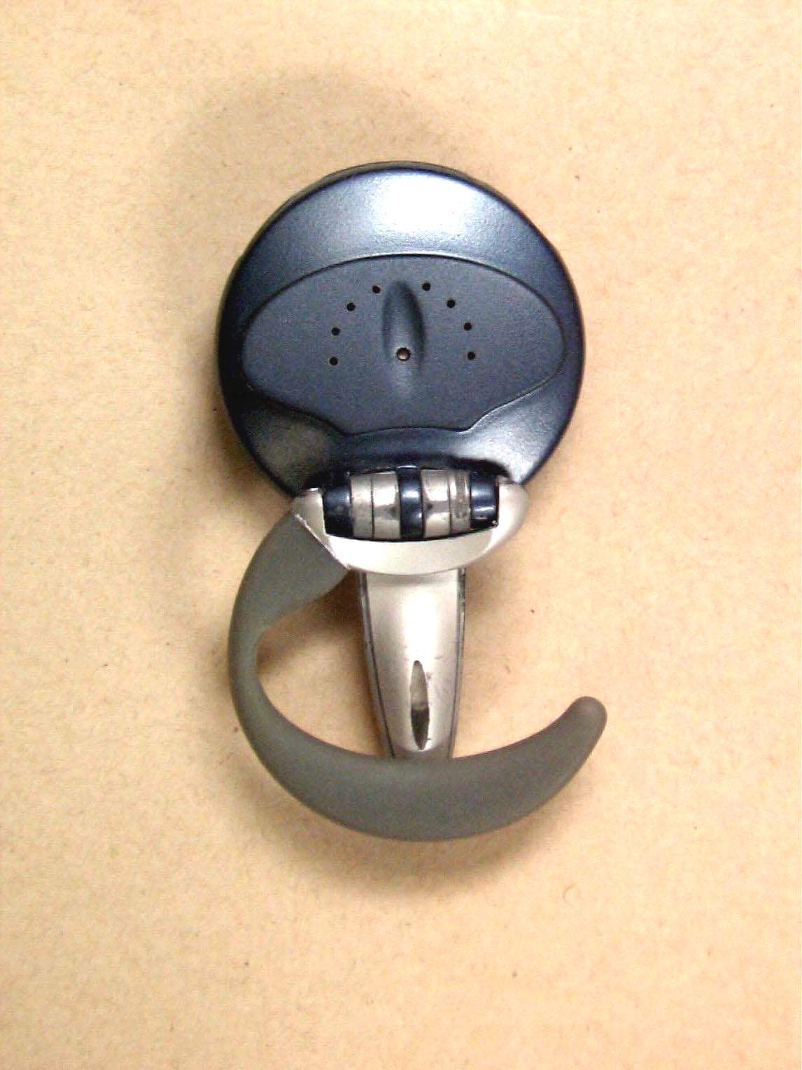
Click to zoom
Application Details
- Equipment Class
- DSS - Part 15 Spread Spectrum Transmitter
- Date of Grant
- Sep 16, 2001
- Application Purpose
- Original Equipment
- Date of Application
- Sep 16, 2001
- Equipment Note
- Series 9200 Bluetooth Wireless Headset
- Frequency Range
- 2402.00000000 - 2480.00000000
- Company
- GN Audio USA Inc.
- Country
- United States
Documents & Files
Document Text
Text extracted from the exhibit documents filed with the FCC. Open a document above to read the original.
Users Manual
SERIES 9200 BLUETOOTH WIRELESS HEADSET USERS MANUAL (July 2001, Preliminary) GN Netcom Inc 77 Northeastern Blvd. Nashua N.H. 03062 Series 9200 Bluetooth Wireless Headset Introduction The Series 9200 Headset is a lightweight “over the ear” wireless headset utilizing Bluetooth technology in the 2.4 GHz band for a short range (up to 10 meters) RF link. The headset contains a microphone and a receiver, and is intended for hands free communications with mobile telephones containing Bluetooth compatibility or any other device that has a Bluetooth Audio Gateway. Headset power is provided by a rechargeable battery. The battery can be charged with a vehicular charge adapter or an AC charge adapter. Battery Life is approximately 3 hours {“Talk Time”) and 100 hours standby (“Sniff”) time The headset has the following user operated controls (see Figure 1): 1. Boom Switch---The power is OFF when the microphone boom is in the closed position and the power is ON when the microphone boom is in the open position. 2. Function Button---This button is pushed for various lengths of time to initiate a call, hang up a call, pairing, transferring a call to a headset, and microphone mute. 3. Volume Rocker Switch---The upper portion of this switch is pushed momentarily to INCREASE the receive volume in steps and the lower portion of this switch is pushed momentarily to DECREASE the receive volume in steps. The headset has the following visual indicator: Blue LED at tip of microphone boom---LED flashes at various rates and durations to indicate Power ON/OFF, Charging, Search & Pairing, BT Link Established, Standby/Sniff Mode, and Audio Link (on a call) The headset has the following audio indicator: Tone in receiver---Tone varies in duration, duty cycle and frequency to indicate Volume Steps, Volume Min, Volume Max, Low Battery, Microphone Mute, Incoming Call, and Pairing I Series 9200 Bluetooth Headset Operation---Preliminary 1. The battery must be charged before using. 2. To charge battery plug charger connector into rectangular Charge Jack located on edge of housing opposite microphone boom hinge. (Note that the headset is not functional while charging and the microphone boom can be open or closed). Select 4-hour charge rate on charger and charge battery. The Blue LED in the tip of the microphone boom will stay ON during charging and go OFF when charging is complete (and the charger is still plugged in). 3. The headset is supplied for use on the right ear. For left ear use open the ear loop 90 degrees from the closed position, carefully snap ear loop off of hinge, rotate 180 degrees and snap back onto hinge. II Pairing with Mobile Phone (Mobile phone must be Bluetooth compatible.) (Note: The Auto Pairing Mode will be entered when the boom is opened if not already paired. Pairing must be done every time the headset establishes a link with a different mobile phone or other Bluetooth compatible device) 1. Verify power of mobile phone to be paired with is ON and phone is within 10 feet of headset. 2. Open headset microphone boom to switch headset power ON. 3. Within 3 seconds after the microphone boom is opened press the Function Button for 2 seconds. 4. Note that the Blue LED will flash ON & OFF for ½ second durations until the Bluetooth pairing has been completed. When pairing has been completed the Blue LED will go ON steady for 5 seconds followed by a series of 10 rapid flashes. Also, a ½ second 2 kHz beep will be heard from the receiver. 5. To establish an Audio Connection with mobile phone after pairing: Select Settings, Connection , Bluetooth Link, Handsfree, and Scan All on mobile phone. Enter Headset PIN # (xxxx) when prompted. Select Link on phone to establish Audio Connection. 6. If pairing fails, the Blue LED will go OFF. III Receiving an Incoming Call 1. Place the headset on your ear after opening the microphone boom fully, opening the ear hook 90 degrees, placing the earhook over your ear, and close the earhook so the receiver is close to your ear. The microphone boom should be pointed toward your mouth. 2. If there is an incoming call while the headset boom is open and the devices are paired, the call will automatically be answered by the headset. When on a call, the Blue LED will flash at a rate of 1 second ON and 1 second OFF. 3. If the BT link has been established and the headset is in “Sniff Mode” (The headset is powered up for approximately 5 minutes after opening the boom and approximately 5 minutes after a call is completed, then it goes into “Sniff Mode” to conserve battery life. The Blue LED blinks at a rate of 1/10 second ON and 2.9 seconds OFF when in “Sniff Mode”.), an incoming Call Alert can be answered by pressing the Function Button momentarily. (The Incoming Call Alert is 1 second of 700 Hz Warble Tone.) 4. To adjust the Receive Volume Up, momentarily press the upper end of the rocker switch one or more times until the desired level is achieved. A ½ second 2 kHz beep will be heard when the max volume is reached. 5. To adjust the Receive Volume Down, momentarily press the lower end of the rocker switch one or more times until the desired level is achieved. A ½ second 2 kHz beep will be heard when the min volume is reached. IV Making an Outgoing Connection 1. If the headset is powered up, dialing can be done from the cell phone or by Voice Dialing if available 2. If the headset is in the “Sniff Mode” press the Function Button for more than 2 seconds and release. Dialing can be done from the cell phone or by Voice Dialing if available. VI Other Functions 1. Microphone Mute can be accomplished while on a call by momentarily pressing the Function Button to mute and un-mute. When the microphone is muted, two 150 millisecond 2 kHz beeps are heard in the receiver every 15 seconds. 2. Low Battery Warning is indicated by five 50 millisecond 2 kHz beeps in the receiver every 20 seconds. 3. Out of Range is indicated by deterioration of audio quality (noisy signal) in the receiver. 4. Power ON/OFF …
Text truncated - open the document above for the full version.
Block Diagram
Thor BT Headset Block Diagram GN Netcom doc. ID: - Date: 2001-08-17File: Thor BlkDia.docRef.: JDJRev.: 1Page: 1 of 1 page(s) This document and the information contained is property of RTX Telecom A/S, Denmark. Unauthorized copying is not allowed. The information in this document is believed to be correct at the time of writing. RTX Telecom A/S reserves the right at any time to change said content, circuitry and specifications. Block Diagram Thor BT Headset RF Receiver RF transmitter Microcontrol- ler Base band DSP RF Syntheiser Bluetooth single chip Flash prom LNA Balun SwitchBPF Antenna TXEN Keyboard Display (1LED) CODEC Amplifier MIC. Speaker Power Supply 3.0V + - Battery VBAT = 3.8V Charge Control + - < feedback External Charging Connector VBAT Off while charging
External Photos
ELECTRONIC TECHNOLOGY SYSTEMS DR.GENZ GMBH REGISTRATIONNUMBER:G0M20107-5099-T-47 ELECTRONIC TECHNOLOGY SYSTEMS DR. GENZ GMBH STORKOWER STR. 38C, D-15526 REICHENWALDE B. BERLIN Appendix Page 1 of 12 Appendix A. Pictures ELECTRONIC TECHNOLOGY SYSTEMS DR.GENZ GMBH REGISTRATIONNUMBER:G0M20107-5099-T-47 ELECTRONIC TECHNOLOGY SYSTEMS DR. GENZ GMBH STORKOWER STR. 38C, D-15526 REICHENWALDE B. BERLIN Appendix Page 2 of 12 ELECTRONIC TECHNOLOGY SYSTEMS DR.GENZ GMBH REGISTRATIONNUMBER:G0M20107-5099-T-47 ELECTRONIC TECHNOLOGY SYSTEMS DR. GENZ GMBH STORKOWER STR. 38C, D-15526 REICHENWALDE B. BERLIN Appendix Page 3 of 12
ID Label/Location Info
scale 1/1 scale 2/1 Bluetooth Headset Model: SYN9006 Series 9200 T M S/N: FCC ID: Made in: MAC Addr: BCESERIES9200 Denmark F.C.12 ITE E210538 Bluetooth Headset Model: SYN9006 Series 9200 T M S/N: FCC ID: Made in: MAC Addr: BCESERIES9200 Denmark F.C.12 ITE E210538 2001 GN Netcom as. All rights reserved. ECO. NO.:67639-10-0154-02391/1A2 2 c DATE:PAGE OF PAGES. Tolerances: Where nothing else is indicated, according to ISO2768-mK All dimensions are in mm. Drawing No.:REVISION:SCALE:
ID Label/Location Info
Thor Series 9200 Headset FCC Label Location The label is located in the battery compartment of the headset and is visible when the battery compartment cover is removed.
Internal Photos
ELECTRONIC TECHNOLOGY SYSTEMS DR.GENZ GMBH REGISTRATIONNUMBER:G0M20107-5099-T-47 ELECTRONIC TECHNOLOGY SYSTEMS DR. GENZ GMBH STORKOWER STR. 38C, D-15526 REICHENWALDE B. BERLIN Appendix Page 4 of 12 ELECTRONIC TECHNOLOGY SYSTEMS DR.GENZ GMBH REGISTRATIONNUMBER:G0M20107-5099-T-47 ELECTRONIC TECHNOLOGY SYSTEMS DR. GENZ GMBH STORKOWER STR. 38C, D-15526 REICHENWALDE B. BERLIN Appendix Page 5 of 12 ELECTRONIC TECHNOLOGY SYSTEMS DR.GENZ GMBH REGISTRATIONNUMBER:G0M20107-5099-T-47 ELECTRONIC TECHNOLOGY SYSTEMS DR. GENZ GMBH STORKOWER STR. 38C, D-15526 REICHENWALDE B. BERLIN Appendix Page 6 of 12 ELECTRONIC TECHNOLOGY SYSTEMS DR.GENZ GMBH REGISTRATIONNUMBER:G0M20107-5099-T-47 ELECTRONIC TECHNOLOGY SYSTEMS DR. GENZ GMBH STORKOWER STR. 38C, D-15526 REICHENWALDE B. BERLIN Appendix Page 7 of 12
Operational Description
Thor BT Headset Thor Series 9200 Headset Operational Description GN Netcom doc. ID: - Date: 2001-08-22File: Thor OpDes.docRef.: JDJRev.: 1Page: 1 of 3 page(s) This document and the information contained is property of RTX Telecom A/S, Denmark. Unauthorized copying is not allowed. The information in this document is believed to be correct at the time of writing. RTX Telecom A/S reserves the right at any time to change said content, circuitry and specifications. Thor Series 9200 Headset Operational Description Thor BT Headset 1 Introduction...........................................................................................................................2 2 User Operated Controls........................................................................................................2 3 Indicators...............................................................................................................................2 4 RF Scheme of Operation.......................................................................................................2 Document history: Rev.Descriptiondate/init. 1Released010822/JDJ Thor BT Headset Thor Series 9200 Headset Operational Description GN Netcom doc. ID: - Date: 2001-08-22File: Thor OpDes.docRef.: JDJRev.: 1Page: 2 of 3 page(s) This document and the information contained is property of RTX Telecom A/S, Denmark. Unauthorized copying is not allowed. The information in this document is believed to be correct at the time of writing. RTX Telecom A/S reserves the right at any time to change said content, circuitry and specifications. 1 Introduction The Series 9200 Headset is a lightweight “over the ear” wireless headset utilizing Bluetooth technology in the 2.4 GHz band for a short range (up to 10 meters) RF link. The headset contains a microphone and a receiver, and is intended for hands free communications with mobile telephones containing Bluetooth compatibility or any other device that has a Bluetooth Audio Gateway. Headset power is provided by a rechargeable battery. The battery can be charged with a vehicular charge adapter or an AC charge adapter. 2 User Operated Controls The headset has the following user operated controls: - 1. Boom Switch: The power is OFF when the microphone boom is in the closed position and the power is ON when the microphone boom is in the open position. - 2. Function Button: This button is pushed for various lengths of time to initiate a call, hang up a call, pairing, transferring a call to a headset, microphone mute and call waiting. - 3. Volume Rocker Switch: The upper portion of this switch is pushed momentarily to increase the receive volume in steps and the lower portion of this switch is pushed momentarily to decrease the receive volume in steps. 3 Indicators A Blue LED at tip of microphone boom flashes at various rates and durations to indicate Power ON/OFF, Charging, Search & Pairing, BT Link Established, Standby/Sniff Mode, and Audio Link (on a call). Tones in receiver vary in duration, duty cycle and frequency to indicate Volume Steps, Volume Min, Volume Max, Low Battery, Microphone Mute, Incoming Call, and Pairing. 4 RF Scheme of Operation The channel is represented by a pseudo-random hopping sequence hopping through the 79 RF channels. The unique hopping sequence is determined by the Bluetooth device address of the master; the phase in the hopping sequence is determined by the Bluetooth clock of the master. The channel is divided into time slots where each slot corresponds to an RF hop frequency. Consecutive hops correspond to different RF hop fre-quencies. The nominal hop rate is 1600 hops/s. All Bluetooth units participating in a piconet are time- and hop-synchronized to the channel. The channel is divided into time slots, each 625 μs in length. In the time slots, master and slave can transmit packets. A TDD scheme is used where master and slave alternatively transmit. The RF hop frequency shall remain fixed for the duration of the packet. For a single packet, the RF hop frequency to be used is derived from the current Bluetooth clock value. For a multi-slot packet, the RF hop frequency to be used for the entire packet is derived from the Bluetooth clock value in the first slot of the packet. The RF hop frequency in the Thor BT Headset Thor Series 9200 Headset Operational Description GN Netcom doc. ID: - Date: 2001-08-22File: Thor OpDes.docRef.: JDJRev.: 1Page: 3 of 3 page(s) This document and the information contained is property of RTX Telecom A/S, Denmark. Unauthorized copying is not allowed. The information in this document is believed to be correct at the time of writing. RTX Telecom A/S reserves the right at any time to change said content, circuitry and specifications. first slot after a multi-slot packet shall use the frequency as determined by the current Bluetooth clock value. If a packet occupies more than one time slot, the hop frequency applied shall be the hop frequency as applied in the time slot where the packet transmission was started. In total, 5 types of hopping sequences are defined: - A page hopping sequence with 32 unique wake-up frequencies distributed equally over the 79MHz, with a period length of 32. - A page response sequence covering 32 unique response frequencies that all are in an one-to- one correspondence to the current page hopping sequence. - An inquiry sequence with 32 unique wake-up frequencies distributed equally over the 79MHz, with a period length of 32. - A inquiry response sequence covering 32 unique response frequencies that all are in an one- to-one correspondence to the current inquiry hopping sequence. - A channel hopping sequence which has a very long period length, which does not show repetitive patterns over a short time interval, but which distributes the hop frequencies equally over the 79MHz during a short time interval.
Schematics
BT_HEADSET_CSR_V3_RB_001.sch-1 - Fri Jul 06 17:29:39 2001
Test Report
ELECTRONIC TECHNOLOGY SYSTEMS DR. GENZ GMBH TEST - REPORT FCC RULES PART 15 / SUBPART C Test report no.: G0M20107-5099-T-47 FCC ELECTRONIC TECHNOLOGY SYSTEMSSTORKOWER STRASSE 38C, D-15526 REICHENWALDE B. BERLIN DR. GENZ GMBHPHONE +49-33631-888 00 FAX +49-33631-888 66 ETS Dr. Genz GmbH, GermanyRegistration number: G0M20107-5099-T-47Page 1 of 25 ELECTRONIC TECHNOLOGY SYSTEMS DR.GENZ GMBH TABLE OF CONTENTS 1General information 1.1Notes 1.2Testing laboratory 1.3Details of approval holder 1.4Application details 1.5Test item 1.6Test standards 2Technical test 2.1Summary of test results 2.2Test environment 2.3Test equipment utilized 2.4Test Procedure 3Test Results ETS Dr. Genz GmbH, GermanyRegistration number: G0M20107-5099-T-47Page 2 of 25 ELECTRONIC TECHNOLOGY SYSTEMS DR.GENZ GMBH 1General Information 1.1Notes The purpose of conformity testing is to increase the probability of adherence to the essential requirements or conformity specifications, as appropriate. The complexity of the technical specifications, however, means that full and thorough testing is impractical for both technical and economic reasons. Futhermore, there is no guarantee that a test sample which has Passed all the relevant tests conforms to a specification. Neither is there any guarantee that such a test sample will interwork with other genuinely open systems. The existence of the tests nevertheless provides the confidence that the test sample posseses the qualities as maintained and that is performance generally conforms to representative cases of communications equipment. The test results of this test report relate exclusively to the item tested as specified in 1.5. The test report may only be reproduced or published in full. Reproduction or publication of extractes from the report requires the prior written approval of the ELECTRONIC TECHNOLOGY SYSTEMS DR. GENZ GMBH. Tester: 13.08.2001W. Treffke DateETS-Lab.NameSignature Technical responsibility for area of testing: 13.08.2001Dr. Genz DateETSNameSignature ETS Dr. Genz GmbH, GermanyRegistration number: G0M20107-5099-T-47Page 3 of 25 ELECTRONIC TECHNOLOGY SYSTEMS DR.GENZ GMBH 1.2 Testing laboratory 1.2.1Location ELECTRONIC TECHNOLOGY SYSTEM DR. GENZ GMBH (ETS) Storkower Straße 38c D-15526 Reichenwalde b. Berlin Germany Telefon : +49 33631 888 00 Telefax : +49 33631 888 66 1.2.2Details of accreditation status ACCREDITED TESTING LABORATORY Accredited by: Bundesamt für Post und Telekommunikation (BAPT) DAR-REGISTRATION NUMBER: TTI-P-G 126/96-30 ACCREDITED COMPETENT BODY Accredited by: Bundesamt für Post und Telekommunikation (BAPT) DAR-REGISTRATION NUMBER: BPT-ZE-026/96-00 1.3Details of approval holder Name: GN Netcom Inc Street: 77 Northeastern Blvd. Town: Nashua, NH 3062 Country: USA Telephone: +1 603-594-4744 Fax: +1-603-579-5575 Contact: Mr. Robert Lucey Telephone: +1 603-594-4744 ETS Dr. Genz GmbH, GermanyRegistration number: G0M20107-5099-T-47Page 4 of 25 ELECTRONIC TECHNOLOGY SYSTEMS DR.GENZ GMBH 1.4Application details Date of receipt of application: 09.07.2001 Date of receipt of test item: 09.07.2001 Date of test: 09.07.2001 1.5Test item Description of test item: Bluetooth Wireless Headset Type identification: Series 9200 Bluetooth Wireless Headset Brand Name: Motorola Serial number: 027 Photos: See Appendix A Technical data Frequency range: 2.4GHz – 2.4835GHz Frequency ( ch A): 2.402 GHz Frequency (ch B): 2.441 GHz Frequency (ch C): 2.480 GHz TransmitterUnomUnom Power (ch A): Conducted: 0,46 dBmRadiated: 1,32 dBm Power (ch B): Conducted: 0,90 dBmRadiated: 0,29 dBm Power (ch C): Conducted: -1,01 dBmRadiated: -2,73 dBm Antenna transmitter: integral (internal antenna)Antenna gain: 0 dBi Antenna receiver: integral (internal antenna) Power supply : 3.8 V DC battery Operating mode: duplex Type of modulation: FHSS ETS Dr. Genz GmbH, GermanyRegistration number: G0M20107-5099-T-47Page 5 of 25 ELECTRONIC TECHNOLOGY SYSTEMS DR.GENZ GMBH Manufacturer: (if applicable) Name: Street: Town: Country: Additional information:The manufacturer declared, that the GN Netcom „Series 9200“ Bluetooth Wireless Headset has also been named „Thor“ during development. „Series 9200“ and „Thor“ is one and the same Bluetooth Wireless Headset. ETS Dr. Genz GmbH, GermanyRegistration number: G0M20107-5099-T-47Page 6 of 25 ELECTRONIC TECHNOLOGY SYSTEMS DR.GENZ GMBH 1.6Test standards Technical standard : FCC RULES PART 15 / SUBPART C § 15.247 2Technical test 2.1Summary of test results No deviations from the technical specification(s) were ascertained in the course ý of the tests performed. or The deviations as specified in 2.5 were ascertained in the course of the tests ̈ performed. 2.2Test environment Temperature: 25 o C Relative humidity content: 20 ...75 % Air pressure: 86 ...103 kPa Details of power supply: 3.8 V DC (battery) Extrem conditions parameters:: ETS Dr. Genz GmbH, GermanyRegistration number: G0M20107-5099-T-47Page 7 of 25 ELECTRONIC TECHNOLOGY SYSTEMS DR.GENZ GMBH 2.3Test equipment utilized No.Measurement device:Type:Manufacturer: ETS 0001Test receiverESHS 10Rohde&Schwarz ETS 0002Test receiverESVPRohde&Schwarz ETS 0003Test receiverESVS 10Rohde&Schwarz ETS 0004Spektrum- and Network-AnalyzerFSMS 26Rohde&Schwarz ETS 0005Test receiverSMV 11MEB ETS 0006Test receiver systemSME 12MEB ETS 0007Spectrum analyzerPSA-65AAvcom ETS 0008AntennaLoop antennaSiemens ETS 0009AntennaLoop antennaMEB ETS 0010AntennaLoop antennaMEB ETS 0011Antennavan Veen/ FrameETS ETS 0012AntennaHK 116Rohde&Schwarz ETS 0013AntennaHL 223Rohde&Schwarz ETS 0014AntennaHL 025Rohde&Schwarz ETS 0015AntennaHL 025Rohde&Schwarz ETS 0016AntennaVHAPSchwarzbeck ETS 0017AntennaVHAPSchwarzbeck ETS 0018AntennaUHAPSchwarzbeck ETS 0019AntennaUHAPSchwarzbeck ETS 0020AntennaDP 21MEB ETS 0021AntennaDP 3MEB ETS 0022AntennaSAS-200/ 521A.H. Systeme / USA ETS 0023AntennaDP 1MEB ETS 0024Antenna mastAF 2MEB ETS 0025Antenna mastAF 2MEB ETS 0026TripodHeinrich Deisel ETS 0027TripodHeinrich Deisel ETS 0028TripodSTA 2C. Lorenz AG ETS 0029TripodBerlebach ETS 0…
Text truncated - open the document above for the full version.
Test Report
Page 1 of 11 PG Results 23 March 2001 Filename: BlueCore01_BC01b_PG_Results_v2.1 MEMORANDUM Distribution:Peter Flittner, Robert Young, James Collier cc: Prepared By:Alex Busteed Subject:Results of Processing Gain Tests for FCC Qualification 1 INTRODUCTION This memo presents the results of the Processing Gain (PG) tests carried out for FCC qualification of the Cambridge Silicon Radio BC01B Bluetooth chip. The FCC states that the PG from a hybrid Bluetooth receiver must be greater than 17 dB when measured in accordance with the Continuous Wave (CW) jamming margin method. Testing of the BC01b has found the PG due to the DS section to be approximately 5 dB and the PG due to the FH part to be approximately 15 dB. It is therefore concluded that the BC01B complies with the FCC PG requirements for radio communication systems. The rest of this paper outlines the PG measurement technique and discusses the test results. Appendix A contains a list of test equipment and Appendix B contains a printout of the measurement results. 2 METHOD 2.1 PG Definition The Processing Gain from a frequency hopping communication system is derived from two parts, the FH section and the DS section. The PG due to FH is given by a simple equation and is constant. However measurement of the PG due to DS is a little more complex. One technique is to use the CW jamming margin method. This method measures PG due to DS using the following algorithm: A CW signal generator is stepped in 50kHz increments across the passband of the system, recording at each point the generator level required to produce the 0.1% Packet Error Rate (PER). This is the jammer level. This level is then referenced to the output power of the intended Bluetooth signal and the Jammer to Signal Ratio JSR is thus calculated. The worst 4 Page 2 of 11 PG Results 23 March 2001 JSR measurements are discarded and the worst remaining JSR is used to calculate the PG due to DS as follows: sysp LJSRSNRG++= min where G p = the processing gain of the system, SNR = the signal to noise ratio required for 0.1% BER, JSR min = minimum J/S ratio and L sys = system losses. 2.2 PG Measurement Technique Figure 1 provides an overview of the PG measurement technique. The measurement is performed in two parts, measurement of the system SNR and measurement of JSR min . Figure 1: PG Measurement Technique The system SNR is calculated using the following algorithm. Generate Bluetooth PRBS-9 packets using a BC01B emulator (1) and a Vector Signal Generator (2). Combine this signal with white noise of a constant level, which is generated using a noise source (4) and a CW Signal Generator (3). Then vary the level of the Bluetooth signal until the BER measured by the BC01B (7) is 0.1%. The resulting SNR is the signal level divided by the Noise level. Page 3 of 11 PG Results 23 March 2001 The JSR for a given jamming frequency is calculated using the following algorithm. Generate Bluetooth PRBS-9 packets using the BC01B emulator (1) and the Vector Signal Generator (2). Combine this signal with a constant CW tone at the jamming frequency using a CW Signal Generator (5) and a combiner (6). Then vary the level of the Bluetooth signal until the PER measured by the Casira Bluetooth Module (7) is 0.1%. The resulting JSR is the signal level divided by the jamming level. 3 RESULTS 3.1 Overview The measurements found that the PG due to DS caused by the access code in page and inquiry mode is found to be approximately 5dB when the access code is a relatively random mixture of 1's and 0's. A random access code causes the most Inter Symbol Interference (ISI) and hence the worst PG for a hybrid system. Therefore only the results for this access code are used in the PG calculation. The PG due to FH is given as PG FH = 10 log 10 (number of frequency hops) The number of hops in a Bluetooth system is 32, therefore the PG due to FH is approximately 15 dB. When this is added to the PG due to DS, the total PG for the BC01B is approximately 20 dB, above the minimum PG requirement for FCC qualification. 3.2 Detailed Results Test Date:17/11/00 Sample Time: 30 seconds Access Code: c6967e Signal Frequency:2.432GHz Receiver Sensitivity: -88.7 dBm Jammer Signal Level:-85.7 dBm Measured SNR: 18.8dB System Losses: 2dB To calculate processing gain, ignore the worst 20% of data points and then apply the following formula: Page 4 of 11 PG Results 23 March 2001 sysp LJSRSNRG++= min Where G p = Processing Gain of the module SNR = signal to noise ratio of the module JS min = minimum J/S ratio after the worst 20% of J/S samples have been discarded L sys = System losses A total of 20 samples were taken by stepping the jamming signal frequency offsets in 50kHz increments over the bandwidth of the receiver. The worst 4 samples were found at –500kHz, -450kHz, -400kHz and 500kHz and were discarded. The remaining minimum J/S ratio was found to be -15.4dB at an offset of +350kHz Thus, the processing gain due to direct sequence spreading in page and inquiry mode is dBG p 4.524.158.18=+−= -500-400-300-200-1000100200300400500 -30 -25 -20 -15 -10 -5 0 5 Jamming Frequency Offset (kHz) J/S (dBs) J/S ratio performance for Processing Gain FCC Testing Page 5 of 11 PG Results 23 March 2001 APPENDIX A - TEST EQUIPMENT LIST Reference:Instrument TypeName 1BlueCore Emulator BoardN/A 2Vector Signal GeneratorIFR2052 3CW Signal GeneratorIFR2025 4White Noise GeneratorHP33120A 5RF MixerM8HC-7 6RF Combiner6 dB loss combiner 7Bluetooth Motherboard and BC01B Module Casira Development Kit 85V, 4A DC Power SupplyN/A 9Spectrum AnalyserHP E4405B Page 6 of 11 PG Results 23 March 2001 APPENDIX B - TEST RESULTS Timestamp: 14:42.43, 16/11/2000 Signal Freq = 2.432 GHz Jammer Level = -85.7 dBm Jammer Offset = -500 kHz Level = -68.7 dBm BER = 0.03% PER = 0.01% SER1 = 0.01% SER2 = 0.01% Level = -70.7 dBm BER = 0.32% PER = 0.79% SER1 = 0.79% SER2 = 0.79% Level = -69.7 dBm BER = 0.11% PER = 0.18% SER1 = 0.18% SER2 = 0.18% Level = -68.7 dBm BER = 0.04% PER = 0.03% SER1 …
Text truncated - open the document above for the full version.
Test Setup Photos
ELECTRONIC TECHNOLOGY SYSTEMS DR.GENZ GMBH REGISTRATIONNUMBER:G0M20107-5099-T-47 ELECTRONIC TECHNOLOGY SYSTEMS DR. GENZ GMBH STORKOWER STR. 38C, D-15526 REICHENWALDE B. BERLIN Appendix Page 8 of 12 ELECTRONIC TECHNOLOGY SYSTEMS DR.GENZ GMBH REGISTRATIONNUMBER:G0M20107-5099-T-47 ELECTRONIC TECHNOLOGY SYSTEMS DR. GENZ GMBH STORKOWER STR. 38C, D-15526 REICHENWALDE B. BERLIN Appendix Page 9 of 12 ELECTRONIC TECHNOLOGY SYSTEMS DR.GENZ GMBH REGISTRATIONNUMBER:G0M20107-5099-T-47 ELECTRONIC TECHNOLOGY SYSTEMS DR. GENZ GMBH STORKOWER STR. 38C, D-15526 REICHENWALDE B. BERLIN Appendix Page 10 of 12 ELECTRONIC TECHNOLOGY SYSTEMS DR.GENZ GMBH REGISTRATIONNUMBER:G0M20107-5099-T-47 ELECTRONIC TECHNOLOGY SYSTEMS DR. GENZ GMBH STORKOWER STR. 38C, D-15526 REICHENWALDE B. BERLIN Appendix Page 11 of 12 ELECTRONIC TECHNOLOGY SYSTEMS DR.GENZ GMBH REGISTRATIONNUMBER:G0M20107-5099-T-47 ELECTRONIC TECHNOLOGY SYSTEMS DR. GENZ GMBH STORKOWER STR. 38C, D-15526 REICHENWALDE B. BERLIN Appendix Page 12 of 12
Contact Information
Applicant
Steen Kaiser(Manager, Product Certifications)
Test Firm
Eurofins Product Service GmbHRobert Kschiwan-Kaspar
Technical Specifications
| # | Rule Parts | Frequency Range | Power Output |
|---|---|---|---|
| 1 | 15C | 2.40 GHz - 2.48 GHz | 1.00 mW |
Other Applications from GN Audio USA Inc.
BCE-OTE995
Aug 19, 2026Bluetooth Headset
Equipment Class
DSS - Part 15 Spread Spectrum TransmitterBCE-HSC240W
Aug 07, 2026Bluetooth Headset
Equipment Class
DSS - Part 15 Spread Spectrum TransmitterBCE-HSC260W
Aug 04, 2026Bluetooth Headset
Equipment Class
DTS - Digital Transmission SystemBCE-OTE800
Mar 24, 2026OTE985 Bluetooth Headset
Equipment Class
DTS - Digital Transmission SystemBCE-OTE810
Mar 19, 2026OTE985 Bluetooth Headset
Equipment Class
DSS - Part 15 Spread Spectrum Transmitter