BFDQ700BP1BP-700
Clear-Com Intercom Systems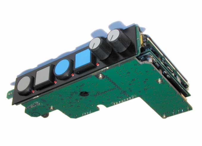
Click to zoom
Application Details
- Equipment Class
- TNT - Licensed Non-Broadcast Transmitter Worn on Body
- Date of Grant
- Jul 10, 2001
- Application Purpose
- Original Equipment
- Date of Application
- Jul 10, 2001
- Equipment Note
- BP-700
- Frequency Range
- 470.00000000 - 740.00000000
- Company
- Clear-Com Intercom Systems
- Country
- United States
Documents & Files
Document Text
Text extracted from the exhibit documents filed with the FCC. Open a document above to read the original.
Users Manual
P R E L I M I N A R Y Q 70 0 W i reless Intercom System O w n e r ’s Manual Q7002 Quick Setup Some info about reading the detail section found later in the manual (indexing this sec- tion would be helpful!) Quick Setup Pro c e d u re #Attach the two wire whip antennas to the BNC connectors on the back panel of the MS-700 master station. #Install the power cord and plug it into the AC source. Turn on the MS-700 with the front panel power switch. #Insert fresh batteries into the BP-700 bodypacks and turn them "on" via the power switch on the main volume control. The power indicator near this c o n t rol should illuminate briefly. #Plug a compatible headset into each BP-700. #Make certain that the operating frequency ranges of the MS-700 and BP-700 match. If there is any question, look at the frequency labels on the bottom of the MS-700 and inside the battery compartment of the BP-700’s. # Verify that the frequency ranges and specific frequencies programmed into the MS-700 and BP-700’s are those authorized for the location. If you are not certain that the currently-programmed frequencies are correct, verify each of them using the procedure on page 7. #Move the BP-700 beltpacks at least 6 feet (2 M) away from the MS-700 and separate them from each other by at least 10 inches (40 cm). #Observe the "RF" LED's on the receiver section of the front panel of the MS-700. The LED corresponding to each active BP-700 should be illuminated. If not, recheck that the BP-700 is turned on and that the frequencies are correct. #In turn, momentarily depress the "B" and "C" pushbuttons on each BP-700. The corresponding receiver "mode" LED's on the MS-700 should illuminate red for pushbutton "B" and green for "C". #Depress the "on" pushbutton on the front panel of the MS-700 for each active receiver channel. The adjacent LED should illuminate to indicate that the channel is selected. #Speak into the headset microphone for each BP-700 while alternately pressing and releasing pushbutton "A" on the unit. You should be able to hear your voice in the headset earpiece in one position or the other. If not, the headset microphone type may be set incorrectly. See page 8 for programming a BP-700 for dynamic or electret microphones. Note: Whether audio is present when the pushbutton is pressed or when it is released depends upon the programmed operating mode of the BP-700. See page 8 for details. #While speaking into each of the BP-700 headset mics, select the corresponding monitor "MON" switch on the MS-700 front panel. Observe the bar-graph LED's on the left side of the MS-700 front panel. The "-2" LED should illuminate frequently on voice peaks, but Q7003 Quick Setup ( c o n t i n u e d ) the "+3" LED should illuminate only rarely. #If necessary, adjust the microphone gain for the BP-700 via the screwdriver adjustment on the top end of the unit. This is the adjustment to the right of the volume control as viewed from the end of the BP-700. #If applicable, connect the wired intercom system to the rear panel of the MS-700. Two intercom channels can be accommodated at the same time. For standard Clear-Com intercom lines, connect line one to the IC1/IC2 XLR connector, and line two to the IC2 connector. For "TW" and RTS systems, both channels are on the same connector, which should be plugged into "IC1/IC2". #Select "Clear-Com" on the rear panel (Clear-Com – TW/RTS pushbutton "in") for standard Clear-Com lines, or "TW/RTS" for Clear-Com two-wire or RTS intercom lines (pushbutton "out"). #On the MS-700 front panel, select one or both intercom channels via the "on" pushbuttons in the intercom area on the panel. The incoming signal can be monitored by selecting the appropriate monitor "MON" pushbutton and observing the bar-graph LED's as described above. #Adjust the intercom input and output levels for the intercom lines as necessary with the front panel "in" and "out" trimmers. If the "null" control requires adjustment, see page 11 “Operational Features.” #If applicable, connect balanced line-level program audio or IFB audio to the "PROG" XLR connector on the MS-700 rear panel. Monitor and adjust level with the corresponding controls on the front panel of the unit. Q7004 I n t ro d u c t i o n Table of Contents Quick Setup . . . . . . . . . . . . . . . . . . . . . . .2 MS-700 Controls and Indicators . . . . . .5 Front Panel . . . . . . . . . . . . . . . . . . . . .5 Rear Panel . . . . . . . . . . . . . . . . . . . . . .6 Programming System Frequencies . . . . .7 BP-700 Beltpack Programming . . . . . . .8 BP-700 Beltpack Batteries . . . . . . . . . .10 Battery Installation . . . . . . . . . . . . .10 System Operation and Features . . . . . .11 System Operation . . . . . . . . . . . . . . .11 Operational Features . . . . . . . . . . . .11 BP-700 Headset Compatibility . . . . .12 Specifications . . . . . . . . . . . . . . . . . . . .13 A word to Vega Users In selecting a Vega intercom system, you are assured of the highest quality and performance. Vega has been the leader in wireless intercom systems for well over a decade. This experience insures you of a Vega Intercom System of quality, performance and reliability. U n p a c k i n g Verify the number of boxes shown “as shipped” and that all have been received in good condition. Unpack your equipment, saving all cartons for storage or reshipping. If, for any reason, you do not find the equipment to be completely satisfactory, please immediately contact your Vega dealer or the Vega factory. Should service ever be required, remember you authorized Vega service dealer knows your equipment best. they have the training and test equipment necessary to restore your equipment to its’ peak performance. And of course, please feel free to contact either you authorized Vega dealer or the Vega factory for information or assistance at any time. I n t ro d u c t i o n Q7005 M S - 70 0C o n t rols and Indicators Summary: This section gives a brief overview of the controls and indicators of th…
Text truncated - open the document above for the full version.
Attestation Statements
Report No. 0519-08 (TX12, RX8) FCC ID: BFDQ700BP12 Page 1 Rev.No 1.0 ATTESTATION STATEMENT SUMMARY: All tests per CFR 47, FCC Part 2, Paragraphs 2.1046; 2.1047(a);(b); 2.1049; 2.1051; 2.1053; 2.1055; Part 74, Paragraph 74.861(e)(1); (e)(3); (e)(5); (e)(6); and 74.861(e)(6)(i)(ii) were ! - Performed The Equipment Under Test ! - Fulfills the requirements of CFR 47, FCC Part 2, Paragraphs 2.1046; 2.1047(a);(b); 2.1049; 2.1051; 2.1053; 2.1055; Part 74, Paragraph 74.861(e)(1); (e)(3); (e)(5); (e)(6); and 74.861(e)(6)(i)(ii). - TÜV PRODUCT SERVICE, INC. - Responsible Engineer: Jim Owen (EMC Engineer)
Block Diagram
0740002AC.sch-1 - Fri Jul 06 10:45:33 2001 0740003AC.sch-1 - Fri Jul 06 10:50:13 2001
Cover Letter(s)
9900 East Baldwin Place, El Monte, California 91731-2294 Telephone: (626) 442-0782 Fax: (626) 444-1342 Toll-Free: 800-877-1771 December 20, 2000 TUV Product Service 10040 Mesa Rim Road San Diego, CA 92121 Re: Request for Confidentiality Dear Sir or Madam: Pursuant to Sections 0.457(d)(1)(ii) and 0.459 of the Commission's Rules, the Applicant hereby requests confidential treatment of information accompanying, as outlined below: Schematics Parts Lists Technical Descriptions The above materials contain trade secrets and proprietary information not customarily released to the public. The public disclosure of these matters might be harmful to the Applicant and provide unjustifiable benefits to its competitors. The Applicant understands that pursuant to Rule 0.457(d)(1)(ii), disclosure of this Application and all accompanying documentation will not be made before the date of the Grant for this Application. Sincerely, Gary Stanfill General Manager Tel: (626) 442-0782 Fax: (626) 444-1342 9900 East Baldwin Place, El Monte, California 91731-2294 Telephone: (626) 442-0782 Fax: (626) 444-1342 Toll-Free: 800-877-1771 December 20, 2000 Chief, Equipment Approval Services Federal Communications Commission P.O. Box 358315 Pittsburgh, PA 15251-5315 Dear Sir or Madam: We, Vega Holdings, Inc., hereby authorize TUV Product Service (10040 Mesa Rim Road, San Diego, CA 92121, Tel. (619) 546-3999) to act as our agent in all matters relating to applications for equipment authorization, including signing of all documents relating to these matters. I further certify that the applicant nor any party to the application is subject to a denial of Federal benefits, that includes FCC benefits, pursuant to Section 5301 of the Anti- Drug Abuse Act of 1988, 21 U.S.C. Section 862. This authorization expires on 1 December 2001. Sincerely, Gary Stanfill General Manager Tel: (626) 442-0782 Fax: (626) 444-1342
External Photos
BP700 BACK BP700 LEFT BP700 PCB FRONT BP700 PCB LEFT BP700 PCB RIGHT BP700 RIGHT
Internal Photos
Receiver TOP, component side Rceiever AUDIO TOP, Component side Transmitter aUDIO top, component side Transmitter rf TOP COMPONENT SIDE WITH SHIELD BP700 PCB REAR BCK ISOMETRIC Transmitter top, component side without shield Display/CONTROl back, component side DISPLAY/CONTROL FRONT LED BUTTON SIDE DC REGULATOR FRONT COMPONENT SIDE BATTERY RETAINER #1 BATTERY CONTACT SIDE BATTERY RETAINER #2 CONTACT SIDE
RF Exposure Info
BP-700 RF Exposure Data The BP-700 beltpack transceiver is worn on the belt on the user's side or back. The transmit antenna extends downward from the waist, away from the head. The antenna normally is held away from the body by the thickness of the plastic case for the unit. The six electronic PCBs in the BP-700 all have large areas of copper, with the majority having one side entirely given over to a full copper plane. The five primary PCBs are also bonded together with metal spacers and grounding straps into one volume, whose dimensions are approximately 1/4 wave over the operating frequency range. As a result, the PCBs are the primary ground plane for the BP-700 transmit antenna, and relatively little energy appears on the headset cable. The headset cable itself is at least 45" long, with the first 12 to 15" routed downwards from the waist before bending upwards again. Due to the cable being more than 1.5 wavelengths long and the 180 degree bend, only a small amount of the energy propagates up the cable to the head. The nominal power output of the BP-700 is 70 mw, with a maximum variation of +/- 1.5 dB. Therefore the maximum power output is less than 100 mw. For a small person weighing only 50 kg, the maximum exposure would be less that 2 mw/kg even if no RF power is radiated externally. The BP-700 transmitter is also normally operated in the PTT mode, with an intermittent transmission, typically with a duty cycle of less than 30%. From this information, it is concluded that the BP-700 is well inside the established RF exposure guidelines. In addition, Table 2 of Appendix A to OET Bulletin 65 indicates that for the applicable subparts of Part 74, no evaluation is required. As a precaution, it is requested that the following statement be added under Item 14 of FCC For 731: "This device and its antenna must not be co-located or operated in conjunction with any other antenna or transmitter. End-users must be provided with specific operating instructions for satisfying RF exposure compliance."
Test Report
Report No. 0519-08 (TX8, RX4; TX12, RX8; TX4, RX12) (FCC ID: BFDQ700BP1) Page 1 Rev.No 1.0 TÜV PRODUCT SERVICE 10040 Mesa Rim Road San Diego, CA 92121-2912 Phone 858 546 3999 FAX 858 546 0364 MEASUREMENT AND TECHNICAL REPORT VEGA WIRELESS 9900 East Baldwin Place El Monte, CA 91731-1342 DATE: 5 May 2001 This Report Concerns: Original Grant: XClass II Change: Equipment Type: Belt Pack, BP-700 (Splits: TX8, RX4; TX12, RX8; and TX4, RX12 Deferred grant requested per 47 CFR 0.457(d)(1)(ii)? Yes: Defer until: No: X Company Name agrees to notify the Commission by: N/A of the intended date of announcement of the product so that the grant can be issued on that date. Transition Rules Request per 15.37? Yes:*No: X (*) FCC Part 2, Paragraphs 2.1046; 2.1047(a);(b); 2.1049; 2.1051; 2.1053; 2.1055; Part 74, Paragraph 74.861(e)(1); (e)(3); (e)(5); and (e)(6) Report Prepared by: TÜV PRODUCT SERVICE 10040 Mesa Rim Road San Diego, CA 92121-2912 Phone: 858 546 3999 Fax: 858 546 0364 Report No. 0519-08 (TX8, RX4; TX12, RX8; TX4, RX12) (FCC ID: BFDQ700BP1) Page 2 Rev.No 1.0 TÜV PRODUCT SERVICE 10040 Mesa Rim Road San Diego, CA 92121-2912 Phone 858 546 3999 FAX 858 546 0364 TABLE OF CONTENTS Pages 1 GENERAL INFORMATION 3 1.1Product Description3 1.2Related Submittal Grant5 1.3Tested System Details5 1.4Test Methodology5 1.5Test Facility5 1.6Part 2 Requirements6 2 SYSTEM TEST CONFIGURATION 7 2.1Justification7 2.2EUT Exercise Software7 2.3Special Accessories7 2.4Equipment Modifications7 2.5Configuration of Tested System7 3RADIATED EMISSION EQUIPMENT/DATA 8 Field Strength Calculation 9 4 CONDUCTED EMISSION, RF POWER OUTPUT, OCCUPIED BANDWIDTH, MODULATION CHARACTERISTICS, FREQUENCY STABILITY EQUIPMENT/DATA 10 5ATTESTATION STATEMENT 40 Report No. 0519-08 (TX8, RX4; TX12, RX8; TX4, RX12) (FCC ID: BFDQ700BP1) Page 3 Rev.No 1.0 TÜV PRODUCT SERVICE 10040 Mesa Rim Road San Diego, CA 92121-2912 Phone 858 546 3999 FAX 858 546 0364 1 GENERAL INFORMATION 1.1Product Description EUT DescriptionWireless Intercom Beltpack EUT NameBP-700 Beltpack Model No.:BP-700Serial No.:002 Product Options:Nine Frequency Splits for North America, Splits 4 through 12 Configurations to be tested:Frequency Split TX8 and RX4 Power Requirements Voltage:Battery (If battery powered, make sure battery life is sufficient to complete testing.) Typical Installation and/or Operating Environment Sound Stage, Theater, Film Set, News Set, Sporting Events, Venues EUT Interface Ports and Cables InterfaceShielding TypeTypeTermination Connector TypePort Termination EXAMPLE: RS232 ! "2 " ! Foil over braidCoaxial Metallized 9- pin D-Sub Characteristic Impedance 6 " ! RS2321Braid2.5 mm1 Head Set1BraidXLR1 EUT Operating Modes to be Tested 1.RX continuous on. TX, modes PTT, PTM EUT System Components - DescriptionModel #Serial #FCC ID # Wirless Intercom BeltpackBP-700002BFDQ700BP8 Report No. 0519-08 (TX8, RX4; TX12, RX8; TX4, RX12) (FCC ID: BFDQ700BP1) Page 4 Rev.No 1.0 TÜV PRODUCT SERVICE 10040 Mesa Rim Road San Diego, CA 92121-2912 Phone 858 546 3999 FAX 858 546 0364 Support Equipment DescriptionModel #Serial #FCC ID # Interface Program BoxQPA-1001N/A PCDOS version S/WN/AN/A Oscillator Frequencies Frequency Derived FrequencyComponent # / LocationDescription of Use 4.9152 Mhz4.9152 MhzY1, U1 on Beltpack Microcontroller PWB Schematic 072-0183 Microcontroller Clock 275.6-335.6 Mhz 275.6-335.6 Mhz Z2, Q3,Q4 on TX PWB Schematic 072-0185 Pg 1 TX Modulator VCO 775.6-1045.6 Mhz 775.6-1045.6 Mhz Z1, Q1, Q2 on TX PWB Schematic 072-0185 Pg 1 TX UHF VCO 10 Mhz10 MhzY1, U1 on TX RF PWB Schematic 072-0185 Pg 1 TX Synthesizer Reference 32 Khz32 KhzU4-A, U4-B on PWB Schematic 072-0182 Pg 1 TX Sub carrier Oscillator 540-810 Mhz 10 Mhx 59.3 Mhz 540-810 Mhz 10 Mhz 59.3 Mhz Subcarrier Z1, Q4, Q5 on Receiver PWB Schematic 072-0181 Pg 1 Y2, U4 on Receiver PWB Schematic 072-0181 Pg 1 Y1, U12 RX PWB RF PWB Schematic 072-0181 Pg 1 RX VCO for 1 st LO RX PLL Reference RX 2 nd LO Power Supply ManufacturerModel #Serial #Type VEGA9 V to 5 V regN/A Switched-mode:(Frequency) Approximat ely 300 Khz Power Line Filters ManufacturerModel #Location in EUT N/A EMC Critical Detail - Complete ground planes on PWBs, Ferrite beads, RF bypass capacitors Report No. 0519-08 (TX8, RX4; TX12, RX8; TX4, RX12) (FCC ID: BFDQ700BP1) Page 5 Rev.No 1.0 TÜV PRODUCT SERVICE 10040 Mesa Rim Road San Diego, CA 92121-2912 Phone 858 546 3999 FAX 858 546 0364 1 GENERAL INFORMATION (continued) 1.2Related Submittal/Grant None 1.3Tested System Details The FCC IDs for all equipment, plus descriptions of all cables used in the tested system are: None 1.4Test Methodology Purpose of Test:To demonstrate compliance with the ANSI C63.4 setup. Test Performed:X1. 1051Radiated Emission per FCC Part 2, Paragraph 2.1053 X2. Conducted Emissions, FCC Part 2, Paragraphs 2. X3. RF Power Output, Part 2, Paragraph 2. 1046 X4. Occupied Bandwidth, Part 2, Paragraph 2.1049 X5. Modulation Characteristics, Part 2, Paragraph 2.1047 and Part 74, Paragraph 74.861(a) and (b) X6. Frequency Stability, Part 2, Paragraph 2.1055, and Part 74, Paragraph 74.861(e)(4) Both Conducted and radiated testing were performed according to the procedures in FCC/ANSI C63.4 and CSA 108.8 - M1983. Radiated testing was performed at an antenna-to-EUT distance of 3 meters (1 - 10 GHz). 1.5Test Facility The open area test site and conducted measurement data were tested by: TÜV PRODUCT SERVICE 10040 Mesa Rim Road San Diego, CA 92121-2912 Phone: 858 546 3999 Fax: 858 546 0364 The Test Site Data and performance comply with ANSI 63.4 and are registered with the FCC, 7435 Oakland Mills Rd, Columbia Maryland 21046. All Measurement Data is acquired according to the content of FCC Measurement Procedure and ANSI C63.4, unless supplemented with additional requirements as noted in the test report. Report No. 0519-08 (TX8, RX4; TX12, RX8; TX4, RX12) (FCC ID: BFDQ700BP1) Page 7 Rev.No 1.0 TÜV PRODUCT SERVICE 10040 Mesa Rim Road San Diego, CA 92121-2912 Phone 858 546 3999 FAX 858 546 0364 2 .S…
Text truncated - open the document above for the full version.
Test Setup Photos
MODULATION LIMITING TEST SETUP Modulation Meter Oscillator Attenuator EUT Mod input portAntenna port CONDUCTED SPURIOUS TEST SETUP and OCCUPIED BANDWIDTH Spectrum Analyzer EUT PEAK POWER OUTPUT SETUP Peak Power Meter EUT Antenna Port Antenna Port FREQUENCY STABILITY SETUP Chamber EUT Spectrum Analyzer
Contact Information
Applicant
Gary Parks
Test Firm
TUV AmericaJames Owen
Technical Specifications
| # | Rule Parts | Frequency Range | Power Output | Emission | Tolerance |
|---|---|---|---|---|---|
| 1 | 74 | 470 MHz - 740 MHz | 75.00 mW | 130F8E | 0.0025000000 % |
Other Applications from Clear-Com Intercom Systems
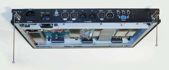
BFDQ700MS1
Jul 10, 2001MS-700
Equipment Class
TNB - Licensed Non-Broadcast Station TransmitterBFD-9525-6
Sep 18, 1996TBT - Licensed Broadcast Transmitter Worn on Body
Equipment Class
TBT - Licensed Broadcast Transmitter Worn on BodyBFD-9526-6
Sep 18, 1996TBF - Licensed Broadcast Transmitter Held to Face
Equipment Class
TBF - Licensed Broadcast Transmitter Held to FaceBFD9516-6
Jan 21, 1996TBF - Licensed Broadcast Transmitter Held to Face
Equipment Class
TBF - Licensed Broadcast Transmitter Held to FaceBFD9517-6
Jan 18, 1996TBT - Licensed Broadcast Transmitter Worn on Body
Equipment Class
TBT - Licensed Broadcast Transmitter Worn on Body