BFYT3017Mobile Cellular Telephone
Shintom Co Ltd
Click to zoom
Application Details
- Equipment Class
- TNB - Licensed Non-Broadcast Station Transmitter
- Date of Grant
- Sep 16, 2002
- Application Purpose
- Original Equipment
- Date of Application
- Feb 09, 2000
- Equipment Note
- Mobile Cellular Telephone
- Frequency Range
- 824.04000000 - 848.97000000
- Company
- Shintom Co Ltd
- Country
- Japan
Documents & Files
Document Text
Text extracted from the exhibit documents filed with the FCC. Open a document above to read the original.
Users Manual
Applicant: Shintom Co., Ltd. Transmitter Type: BFYT3017 EXHIBIT 20 PAGE 1 OF 52 1 Important There are some basic rules that apply to most hardware installation procedures and need to be observed to prevent damage or injury. 1. Always make sure that any power is disconnected to the vehicle before handling any electrical components like wiring, fuseboxes, connectors, etc. 2. Never force any connection between components, electrical connectors or the like. 3. Always use the proper tools for the task at hand. Using improper tools may cause damage to yourself, your vehicle, or your cellular telephone system. 4. Think through all the necessary steps of installation before actually beginning the procedure and equip yourself for all steps to be performed. 5. Always make sure your workspace and your tools are clean and tidy. The introduction of dirt or grease may hinder the performance of your cellular telephone and related components. Installation Procedure 1. Before we begin You will need the following items in order to properly install the cellular telephone in the trunk of an automobile. 1. Cradle(CR91) 2. Mounting Bracket(MT91) 3. Power Cable(EPC91) 4. Extension Cable(EIC91) 5. Clamshell Bracket 6. Screw kit (M4 × 6)(SKM46) (M4 × 10)(SKM410) (M4 × 35)(SKM435) 7. Hands-Free Microphone(MIC91) 8. Installation Guide(OMCMK**) Applicant: Shintom Co., Ltd. Transmitter Type: BFYT3017 EXHIBIT 20 PAGE 2 OF 52 2 2. Mount the Transceiver unit To install the cellular telephone with the transceiver unit located in the trunk-space of the automobile follow the steps outlined below. a. Place the mounting bracket so that the four bracket holes line up with the trans- ceiver holes. b. Replace the four screws (supplied M4 × 6mm) in the screw kit so that the mount- ing bracket is secured to the transceiver unit. c. Place the unit top-side up (bracket feet down), utilizing the included flatwashers, insert the four self-tapping screws (sup- plied M4 × 35mm) and tighten them down. Orange Extension Cable Power Cable fuse 3A fuse 1A Red Black 3. Wiring a. Connect the cables to the mounted transceiver unit using the supplied trunk mount extension cable as illustrated. Car Battery Ground (Black) Back up (Red) Ignition (Orange) Extension cord Hands-Free Mic Cradle Hand Set Transceiver unit Antenna Applicant: Shintom Co., Ltd. Transmitter Type: BFYT3017 EXHIBIT 20 PAGE 3 OF 52 3 4. Mount the Cradle and Handset a. Using a pedestal mount. The cradle unit can be mounted as displayed. Be sure to use only supplied M4 × 10mm screws. Using improper screws will damage the cradle unit. b. Plug in the handset and Hands-Free Mic. c. Check to make sure ALL signal and power leads are in place and properly connected. Hands-Free Mic Applicant: Shintom Co., Ltd. Transmitter Type: BFYT3017 EXHIBIT 20 PAGE 4 OF 52 4 5. Antenna The following is the standard antenna installation for TR93. Antenna type: Glass mount type - Colinear Mount location : Rear window of a vehicle Antenna cable : RG-58/U 8 feet (2.44m) or longer Install the antenna on your vehicle as shown below. Rear window Transceiver unit Antenna Coaxial cable RG-58/U 8 feet or longer Rear window Antenna Applicant: Shintom Co., Ltd. Transmitter Type: BFYT3017 EXHIBIT 20 PAGE 5 OF 52 TR93 MOBILE CELLULAR TELEPHONE OPERATING INSTRUCTIONS PRINTED IN XXXX x-xx 288Exxxx 555 Wireless Blvd., HAUPPAUGE, NY 11788 Applicant: Shintom Co., Ltd. Transmitter Type: BFYT3017 EXHIBIT 20 PAGE 6 OF 52 TELEPHONE Congratulations. By choosing the TR93, you have joined the millions of satisfied customers who are enjoying the benefits and quality performance that only an Audiovox Cellular Tel- ephone can provide. Your Audiovox Mobile Cellular Telephone has been designed to the highest standards of quality and manufacturing excel- lence to fulfill both your personal and business requirements. The Audiovox TR93 is packed with advanced features like Programmable One Touch Emergency Dialing, Anti-Fraud Se- curity Features, Automatic Call Retry, a Constant Signal Strength Indicator. And of course, your new Audiovox TR93 comes with something only an Audiovox phone can provide The proven reliability that has made Audiovox one of the world's leading suppliers of cellular communications equipment. The following pages describe your phone's functions and will help you make the most efficient use of this wonderful com- munications tool. Following codes can be obtained through your selling Audiovox dealer. a. 3-digit Initial Lock (Unlock) Code b. 3-digit Initial Call Restriction Code c. 2-digit Initial Call Counter Code d. 2-digit Initial Call Timer Code Keep these codes in a safe place! TR93 MOBILE CELLULAR Applicant: Shintom Co., Ltd. Transmitter Type: BFYT3017 EXHIBIT 20 PAGE 7 OF 52 1 TABLE OF CONTENTS INTRODUCTION .............................................. 3 Safety Information for Wireless Handheld Phones ................ 3 Features .................................................................................. 7 Key/Display Names and Functions ........................................ 8 INSTALLATION .............................................. 10 Cautions ................................................................................ 10 Parts List ............................................................................... 11 BASIC OPERATION ....................................... 13 Turning the Phone ON and OFF ........................................... 13 Display Own Telephone Number ..................................... 13 Display Own System ID ................................................... 13 Placing Calls ......................................................................... 13 Call-in Progress Protection ............................................... 14 Receiving Calls ..................................................................... 14 Call in Absence Indication ................................................ 14 Silent Incoming Calls ............................................…
Text truncated - open the document above for the full version.
Block Diagram
Applicant: Shintom Co., Ltd. Transmitter Type: BFYT3017 EXHIBIT 15
Block Diagram
Applicant: Shintom Co., Ltd. Transmitter Type: BFTY3017 EXHIBIT 17
External Photos
Applicant: Shintom Co., Ltd.Transmitter Type: BFYT3017 EXHIBIT 7 Front View
External Photos
Applicant: Shintom Co., Ltd.Transmitter Type: BFYT3017 EXHIBIT 8Top View
External Photos
Applicant: Shintom Co., Ltd. Transmitter Type: BFYT3017 EXHIBIT 9 Bottom View
External Photos
Applicant: Shintom Co., Ltd. Transmitter Type: BFYT3017 EXHIBIT 10 Right Side View
External Photos
Applicant:Shintom Co., Ltd. Transmitter Type: BFYT3017 EXHIBIT 11 Left Side View
ID Label/Location Info
SERIAL NO. FCC ID: BFYT3017 Applicant: Shintom Co., Ltd. Transmitter Type: BFYT3017 EXHIBIT 5
ID Label/Location Info
Applicant: Shintom Co., Ltd. Transmitter Type: BFYT3017 EXHIBIT 6 Back View of Showing FCC LABEL
Internal Photos
Applicant:Shintom Co., Ltd. Transmitter Type: BFYT3017 EXHIBIT 12 Front View of PC Board
Internal Photos
Applicant: Shintom Co., Ltd. Transmitter Type: BFYT3017 EXHIBIT 13 Back View of PC Board
Operational Description
Applicant: Shintom Co., Ltd.Transmitter Type: BFYT3017 TECHNICAL DESCRIPTION The transmitter has been specially designed for the Domestic Public Cellular Radiotelephone Communications Service. The rated maximum power output is 3 watts with the capability of reducing the maximum power in seven steps of 4dB each on command from a Base Station. Each power level is maintained within +2/-4 dB of its nominal level over the temperature range from -30 to +60 degrees Centigrade and +15/-15 % change of the supply voltage, accumulative. This transmitter operates in the frequency range of 824.04 to 848.97 MHz. The frequencies are generated by Phase Locked Loop Frequency Synthesizers which are controlled by the closest Base Station in the system and the frequency stability of carrier is better than ±2.5 ppm. The transmitter is equipped with an audio compressor having 2:1 syllabic compandor, a pre-emphasis audio circuit having a 6dB/octave response, an instantaneous deviation limiter to limit deviation to ±12KHz, and a post deviation limiter filter having a -48dB/octave response above 3000 Hz. The transmitter carrier frequency is generated by a Phase Locked Loop (PLL) circuit. The PLL circuit consists of a TX Voltage Controlled Oscillator (TX VCO, MX301), a PLL integrated circuit (IC301), a loop filter and a reference frequency oscillator (TCXO system, see Pages 4 to 6 of Exhibit 3). The frequency of the TCXO system is 14.4 MHz with stability better than ±2.5ppm over the temperature range of -30 to +60 degrees Centigrade. The frequency of TCXO system can be controlled by AFC (Automatic Frequency Control) circuit so that the receiving frequency agrees with the Base Station transmit frequency. In this mode, the frequency stability of TCXO system is maintained within ±1.0ppm over the temperature range of -30 to +60 degrees Centigrade. The reference divider provides a reference signal to the phase comparator by dividing an output of the TCXO system. The programmable divider, which is controlled by digital circuitry, provides a signal to the phase comparator by dividing an output of the TX VCO (MX301). The phase comparator controls a frequency of the TX VCO through the charge pump and the loop filter so that the phase of the signal from the programmable divider agrees with the phase of the reference signal. Therefore, the frequency of the TX VCO is controlled by the digital circuitry with the stability of the TCXO system. The TX PLL synthesizer provides a RF signal to TX driver AMP(Q203). EXHIBIT 4 PAGE 1 OF 2 Applicant: Shintom Co., Ltd.Transmitter Type: BFYT3017 TECHNICAL DESCRIPTION (Continued) The TX PLL circuit also acts as a frequency modulator which provides the peak frequency deviation within ±12 KHz and the constant deviation and low distortion within the operating bandwidth. The frequency modulator is preceded by a Signal Audio Processing LSI (IC403) which contains a band pass filter, compressor, pre-emphasis, limiter, post-limiter filter, and a mute switch, to provide appropriate voice band processing. Supervisory Audio Tone (SAT), Signaling Tone (ST), and Wide Band Data (WBD) are generated within the Signal Audio Processing LSI (IC403) which is controlled by Microprocessor (IC601), and transmitted to the frequency modulator through the filter included in the Signal Audio Processing LSI (IC403). The power amplifier circuit, which consists of a RF power amplifier module (IC201), a band pass filter (F202), the driver (Q203), and a power control circuit, amplifiers the 0.3 milliwatt from the TX PLL synthesizer circuit and provides at least 5 watts output. The output of the power amplifier is connected to an antenna terminal through a directional coupler (F203) and a Band Pass Filter (F101). The output of the power amplifier provides adequate margin to compensate for losses in the directional coupler and bandpass filter. The Power Control circuit (APC) consists of a power level detector (D201), comparator (IC202), and a DA converter incorporated in IC601. The power detector provides the comparator with a DC voltage which indicates the power level. The D/A converter, which is controlled by the digital circuitry provides the reference DC voltage to the comparator. The comparator controls the RF power amplifier module so that the voltage detected by the power level detector is equal to the reference voltage. The D/A converter converts the binary data from the digital circuitry into the analog reference voltage. Binary data, which corresponding to the eight different power levels, is stored in the EEPROM of the digital circuitry and controls the power level adjustment. The transmitter has the capability of reducing the maximum output power level in 7 steps of 4 dB each. The digital circuitry continuously monitors the power output at the output of the power detector. If the power output is detected and the CARRIER ON command is not enabled by the digital circuitry, the transmitter ill be deactivated through independent action of controlling TX Enable Switch (Q301) to turn off the power of TX VCO (MX301) and through action of controlling Power Supply Switch (Q201) with signal (TXTS) to turn off the power of RF Power Amp. Module (IC201), TX Driver Amp (Q203) and Automatic Power Control (IC202). EXHIBIT 4 PAGE 2 OF 2
Parts List/Tune Up Info
Applicant: Shintom Co., Ltd.Transmitter Type: BFYT3017 TUNE-UP PROCEDURE 1. SET-UP FOR TUNE-UP OF TRANSMITTER 2. COMMAND LIST FOR ALIGNMENT COMMANDALIGNMENT ITEMS ---------------------------------------------------- 01 AFC Temperature Sensor 02 Frequency 03 RX Demodulation Level 04 RX RSSI Level for -50dBm 05 RX RSSI Level for -110dBm 06 Power Level of PL0 07 Power Level of PL1 08 Power Level of PL2 09 Power Level of PL3 10 Power Level of PL4 11 Power Level of PL5 12 Power Level of PL6 13 Power Level of PL7 14 Deviation of ST1 15 Deviation of ST3 16 Deviation of ST2 17 Deviation of SAT 18 Deviation of Voice 19 Deviation of DTMF (697Hz/1209Hz) EXHIBIT 21 PAGE 1 OF 4 RX AF Output TX AF Input (RF SG Set-up) Frequency =881.49MHz, Mod.=1KHz, Dev.=2.9KHz Output Level = -50dBm RF Power Meter Deviation Meter RF Signal Generator Adapter for Alignment TR93 Transceiver Under Alignment DC Power Supply 13.7 Volts Audio Level Meter AF Signal Generator Frequency = 1 KHz Output = +10 dBV (Dev. of Limiter) Output = -25 dBV (Dev. of Voice) ANT Handset Applicant: Shintom Co., Ltd.Transmitter Type: BFYT3017 3. ALIGNMENT PROCEDURE EXHIBIT 21 PAGE 2 OF 4 Setting into Alignment Mode Power ON Alignment Input of a Alignment Memorizing a Alignment Value into EEPROM Cancel of the Alignment Power OFF Next Command Applicant: Shintom Co., Ltd.Transmitter Type: BFYT3017 4. KEY OPERATION FROM HANDEST (a) Setting into Alignment Mode Push keys as follows: (b) Input of a Alignment Command Push keys as follows: (c) Alignment Increasing Alignment value: Push a key ( (Up key) Decreasing Alignment value: Push a key ( (Down key) (d) Memorizing a Alignment value into EEPROM Push a key (e) Cancel of the Alignment value into EEPROM Push a key EXHIBIT 21 PAGE 3 OF 4 FNC#643#FNC 0837CLRSEND SEND SEND 2nd digit of a Alignment Command 1st digit of a Alignment Command STO END Applicant: Shintom Co., Ltd.Transmitter Type: BFYT3017 5. ALIGNMENT VALUE ALIGNMENT Measurement Frequency(MHz) Alignment Command (Channel) ------------------------------------------------------------------------------------------ 01 AFC Temperature ------ Room Temperature±3 Sensor 02 Frequency 836.49836.49MHz±200Hz (383) 03 RX Demod Level 881.49-25.0±0.5 dBV (383) 04 RX RSSI Level 881.49 ------ (383) 05 RX RSSI Level 881.49 ------ (383) 06 Power Level 0 836.49 +34.8±0.2 dBm (383) 07 Power Level 1 836.49 +30.8±0.2 dBm (383) 08 Power Level 2 836.49 +26.8±0.2 dBm (383) 09 Power Level 3 836.49 +22.8±0.2 dBm (383) 10 Power Level 4 836.49 +18.8±0.2 dBm (383) 11 Power Level 5 836.49 +14.8±0.5 dBm (383) 12 Power Level 6 836.49 +10.8±0.5 dBm (383) 13 Power Level 7 836.49 +6.8±0.2 dBm (383) 14 ST1 Deviation 824.04 8.0±0.1 KHz (Peak) (991) 15 ST3 Deviation 848.97 8.0±0.1 KHz (Peak) (799) 16 ST2 Deviation 836.49 8.0±0.1 KHz (Peak) (383) 17 SAT Deviation 836.49 2.0±0.1 KHz (Peak) (383) 18 Voice Deviation 836.49 2.9±0.3 KHz (Peak) (383) 19 DTMF Deviation 836.49 8.6±0.3 KHz (Peak) (383) ------------------------------------------------------------------------------------------ EXHIBIT 21 PAGE 4 OF 4
RF Exposure Info
3D-EMC Laboratory, Inc. Product Compliance SARTest Report Product :Shintom Co., Ltd. Model :TR93 FCCID :BFYT3017 Reference no.:10047 3D-EMC Laboratory, Inc. for NEAR FIELD MEASUREMENTS 3D-EMC Laboratory, Inc. TABLE OF CONTENT 1.1 SAR TEST REPORT......................................................................................................................................3 1.2 PRODUCT COMPLIANCE TEST REPORT..............................................................................................5 2.1 GUIDELINES..................................................................................................................................................6 LOCATION OF TEST................................................................................................................................................6 2.2MEASUREMENT SYSTEM SPECIFICATIONS.....................................................................................6 2.3TEST DESCRIPTION...................................................................................................................................7 2.4PHANTOM.....................................................................................................................................................7 2.5SIMULATED TISSUE....................................................................................................................................7 PREPARATION.......................................................................................................................................................8 2.6 MEASUREMENT OF ELECTRICAL CHARACTERISTICSOF SIMULATED TISSUE.................8 DESCRIPTION OF THE SLOTTED COAXIAL WAVEGUIDE............................................................................................9 2.7 SYSTEM DESCRIPTION............................................................................................................................10 2.8 DATA EXTRAPOLATION..........................................................................................................................11 2.9INTERPOLATION AND GRAM AVERAGING......................................................................................11 2.10 POWER MEASUREMENT.......................................................................................................................12 2.11 POSITIONING OF D.U.T..........................................................................................................................12 3.1 DATA..............................................................................................................................................................15 ANTENNAIN......................................................................................................................................................__ TESTINFORMATION............................................................................................................................................__ ATTENUATION VERSUSDEPTHSCAN...................................................................................................................__ AREASCANCONTOURPLOT...............................................................................................................................__ 3D PLOT OFABSORBEDENERGY........................................................................................................................__ ANTENNAOUT..................................................................................................................................................__ TESTINFORMATION............................................................................................................................................__ ATTENUATION VERSUSDEPTHSCAN...................................................................................................................__ AREASCANCONTOURPLOT...............................................................................................................................__ 3D PLOT OFABSORBEDENERGY........................................................................................................................__ SIMULATEDTISSUE...........................................................................................................................................__ SIMULATEDTISSUETESTREPORT.......................................................................................................................__ 3D-EMC Laboratory, Inc. SAR Test Report To: SHINTOM Co., Ltd. Date: 1/11/00 Re: 10047 Radio Information Radio Type : Cellular Transceiver Model Number : TR93 Serial Number : 17400000825 FrequencyBand(MHz) 800 Frequency Tested(MHz)824 Nominal Output Power:(W) 3.0 peek Antenna Type : Colinear Antenna Position: Fixed Signal Type : AMPS Duty Cycle : - Simulated Tissue Type of Tissue : Brain Measured Dielectric Constant: 45.5 Measured Conductivity : 0.89 Conditions Robot : 6 Axis Scan Type : SAR Measured Field: E MeasuredPower(W): 1.839 Phantom Type : Head - Full Body Phantom Position: Horizontal Room Temperature°C: 24.0 Distance Antenna-Shell:10 mm Probe Probe Name : ETR225_1_999 Probe Orientation: - ProbeOffset(mm): 2.25 Sensor Factor : 10.8 Conversion Factor: 0.65 Calibration Date: 11/19/99 Results Maximum Fields Location: X : -25 Y : -10 SAR (averaged over 1 gram of tissue) W/kg : 0.15 CommentsComments @ 824 MHz, 1.839 W – 0.15 W/Kg @ 837 MHz, 1.921 W – 0.10 W/Kg @ 849 MHz, 1.687 W – 0.08 W/Kg (Continue) 3D-EMC Laboratory, Inc. (Note) Insertion loss of adaptercable : 1.62 dB @ 835 MHz (Measured by manufacturer) All the power values listed above are already compensated with the proper insertion loss All the power values listed above are RMS power if it is not notified We measured the power at the terminal of the transceiver directly *WITHOUT* cable We set up the devices so that antenna was fed through cable (this is why negative insertion loss value is shown at t…
Text truncated - open the document above for the full version.
RF Exposure Info
Date: April 3, 2000 EXHIBIT 40 Page 1 of 1 To: Mr.Joe Dichoso FCC Application Processing Branch From:Kenichi Saito Shintom Co., Ltd. (c/o Audiovox Communications Corp.) Re:Response to Correspondence – Correspondence Reference Number: 13064 FCC ID: BFYT3017 Form 731 Confirmation Number: EA96744 Applicant: Shintom Co., Ltd. Dear Mr.Dichoso, The followings are response to your correspondence. 1) The SAR configuration used was selected to simulate worst case condition of exposure to the head of a tall person sitting directly under the antenna. The cable used for the measurement (8 feet) duplicates actual installation. The installation manual has been modified to specify the exact installation procedure, including length of the cable. Please see the revised manual. The pages of manual revised has been submitted as EXHIBIT 41 through Add Attachment of OET Equipment Authorization Electronic Filing. 2) The recommended antenna specified in the installation instruction is a “thru-glass” antenna which is to be mounted on the rear windshield near the center. Because of the positioning of this antenna, it is not possible for anyone standing in the vicinity of the vehicle to come closer than approximately 3 feet from the antenna. Therefore it was not deemed necessary to measure SAR for a body right next to antenna. 3) Please see the revised manual submitted as EXHIBIT 41. Sincerely, Kenichi Saito Director Shintom Co., Ltd. c/o Audiovox Communications Corp. 555 Wireless Blvd., Hauppauge, NY 11788 TEL:631-233-3393 FAX:631-233-3438 E-mail: [email protected]
RF Exposure Info
4 5. Antenna The following are recommended antenna and cable installation instruction for TR93. Antenna Coaxial cable RG-58/U 8 feet or longer Rear window Antenna Applicant: Shintom Co., Ltd. Transmitter Type: BFYT3017 EXHIBIT 20 PAGE 5 OF 52 Rear window Transceiver unit These instructions must be followed in order to comply with the FCC RF exporsure requirements. Antenna type: Glass mount type ("thru-glass" antenna) - Colinear Mount location: Rear window of a vehicle Antenna cable: RG-58/U, 8 feet (2.44m) or longer Install the antenna on the upper portion of the rear window and centered as shown in the diagram below. 3 SAFETY INFORMATION FOR EXPOSURE TO RADIO FREQUENCY SIGNALS Your wireless mobile telephone is a low power radio tran- smitter and receiver. When it is ON, it receives and also se- nds out radio frequency (RF) signals. In August, 1996, the Federal Communications Commission (FCC) adopted RF exposure guidelines with safety levels • ICNIRP (1996) Those standards were based on comprehensive and periodic evaluations of the relevant scientific literature. For example, over 120 scientists, engineers, and physicians from universities, government health agencies, and industry reviewed the av- ailable body of research to develop the ANSI Standard (C95.1). The design of your phone complies with the FCC guidelines (and those standards). Use only the supplied or an approved replacement antenna. Unauthorized antennas, modifications, or attachments could damage the phone and may violate FCC regulations. SAFE PHONE INSTALLATION AND OPERATION For safe and efficient operation, this phone must be properly installed using recommended installation procedure specified in the installation guide for this unit. A "thru-glass" antenna must be mounted on the center of the rear window of the vehicle. At no time should anyone touch the antenna or come in close contact with it while the phone is in operation. Applicant: Shintom Co., Ltd. Transmitter Type: BFYT3017 PAGE 10 OF 52 EXHIBIT 20 ANTENNA CARE WIRELESS MOBILE PHONES READ THIS INFORMATION BEFORE USING YOUR MOBILE CELLULAR TELEPHONE for mobile wireless phones. Those guidelines are consis- tent with the safety standards previously set by both U.S. and International standards bodies: • ANSI C95.1 (1992) • NCRP Report 86 (1986) 4 DRIVING Check the laws and regulations on the use of wireless telephones in the areas where you drive. Always obey them. Also, if using • Use hands-free operation, if available. • Pull off the road and park before making or answering a call if driving conditions so require. ergy. However, RF energy from cellular telephones may af- fect inadequately shielded electronic equipment. RF energy may affect improperly installed or inadequately shielded electronic operating and entertainment systems in motor vehicles. Check with the manufacturer or its repre- sentative to determine if these systems are adequately Consult the manufacturer of any personal medical devices regulations posted in the areas instruct you to do so. Hospit- als or health care facilities may be using equipment that could be sensitive to external RF energy. Applicant: Shintom Co., Ltd. Transmitter Type: BFYT3017 PAGE 11 OF 52 EXHIBIT 20 to your vehicle. shielded from external RF energy. You should also check with the manufacturer of any equipment that has been added your phone while driving, please: • Give full attention to driving - driving safely is your first responsibility. ELECTRONIC DEVICES Most modern electronic equipment is shielded from RF en- (such as pacemakers, hearing aids, etc.) to determine if they are adequately shielded from external RF energy. Turn your phone OFF in health care facilities when any 5 BLASTING AREAS To avoid interfering with blasting operations, turn your unit OFF when in a “Blasting area” or in areas posted “Turn off Sparks in such areas could cause an explosion or fire result- ing in bodily injury or even death. Areas with a potentially explosive atmosphere are often but not always clearly marked. They include fueling areas such as gasoline stations, below deck on boats, fuel or chemical (such as propane or butane), areas where the air contains chemicals or particles, such as: grain, dust,or metal powders, and any other area where you would normally be advised to Applicant: Shintom Co., Ltd. Transmitter Type: BFYT3017 PAGE 12 OF 52 EXHIBIT 20 two-way radio”. Obey all signs and instructions. POTENTIALLY EXPLOSIVE ATMOSPHERES Turn your phone OFF when in any area with a potentially explosive atmosphere and obey all signs and instructions. transfer or storage vehicles using liquefied petroleum gas turn off your vehicle engine. 6 For Vehicles Equipped with an Air Bag An air bag inflates with great force. DO NOT place objects, including both installed or mobile wireless equipment, in the area over the air bag or in the air bag deployment area. If in-vehicle wireless equipment is improperly installed Applicant: Shintom Co., Ltd. Transmitter Type: BFYT3017 EXHIBIT 20 PAGE 13 OF 52 and air bag inflates, serious injury could result.
RF Exposure Info
Date: April 7, 2000 EXHIBIT 42 Page 1 of 1 To: Mr.Joe Dichoso FCC Application Processing Branch From:Kenichi Saito Shintom Co., Ltd. (c/o Audiovox Communications Corp.) Re:Response to Correspondence – Correspondence Reference Number: 13272 FCC ID: BFYT3017 Form 731 Confirmation Number: EA96744 Applicant: Shintom Co., Ltd. Dear Mr.Dichoso, The followings are response to your correspondence. 1. (a) The adapter cable with the insertion loss of 1.62 dB described in 4 th page of the SAR report is 8 feet RG58/U cable, which is the same cable indicated in my previous reply. (b) The output power shown in 3 rd page of the SAR report were compensated with the cable loss of 1.62 dB based on the conducted measured power shown in 14 th page, 21 st page, and 28 th page of the report. The conducted measured power shown in these pages are as follows. 2.67 W at 824 MHz ( 14 th page ) 2.79 W at 836 MHz ( 21 st page ) 2.45 W at 849 MHz ( 28 th page ) (c) The conducted measured power shown in 14 th page, 21 st page, and 28 th page of the SAR report were measured at the terminal of the transceiver directly without cable. (d) The cable through which the antenna was fed is the same cable described in (a). 2. The insertion loss of the 8 feet cable is 1.62 dB. 3. The ERP were measured by using the 8 feet cable described above in 1. (a). Sincerely, Kenichi Saito Director Shintom Co., Ltd. c/o Audiovox Communications Corp. 555 Wireless Blvd., Hauppauge, NY 11788 TEL:631-233-3393 FAX:631-233-3438 E-mail: [email protected]
Schematics
Applicant: Shintom Co., Ltd. Transmitter Type: BFYT3017 EXHIBIT 16
Schematics
Applicant: Shintom Co., Ltd. Transmitter Type: BFYT3017 EXHIBIT 18
Schematics
Applicant: Shintom Co., Ltd. Transmitter Type: BFYT3017 EXHIBIT 19 SCHEMATIC DIAGRAM OF TX VCO IL120
Test Report
Applicant: Shintom Co., Ltd.Transmitter Type: BFYT3017 DESCRIPTIVE INFORMATION SubsectionDescription 2.1033(c)(1)Applicant:Shintom Co., Ltd. 1-19-20 Shin-Yokohama, Kohoku-Ku Yokohama 222-0033, Japan Manufacturer: Shintom Co., Ltd. 2.1033(c)(2)FCC ID: BFYT3017 2.1033(c)(3)Installation and Operating Instructions: See Exhibit 20. 2.1033(c)(4)Emission Types:…
Text truncated - open the document above for the full version.
Contact Information
Applicant
Shuichi Ohmomo(Manager)
Technical Contact
Audiovox Communications Corp.Kenichi Saito
[email protected]631-233-3393
555 Wireless Blvd. · Hauppauge, New York · United States
Non-Technical Contact
Audiovox Communications Corp.Kenichi Saito
[email protected]631-233-3393
Technical Specifications
| # | Rule Parts | Frequency Range | Power Output | Emission | Tolerance |
|---|---|---|---|---|---|
| 2 | 22H | 824.04 MHz - 848.97 MHz | 3 W | 40K0F1D | 2.5 ppm |
Other Applications from Shintom Co Ltd
BFYM5030
Jul 08, 2002Cellular GSM Phone
Equipment Class
PCE - PCS Licensed Transmitter held to ear
BFYVRK6AANAY
May 26, 1999Video Cassette Recorder
Equipment Class
HID - Part 15 TV Interface Device
BFYM3047
Apr 18, 1999TNB - Licensed Non-Broadcast Station Transmitter
Equipment Class
TNB - Licensed Non-Broadcast Station Transmitter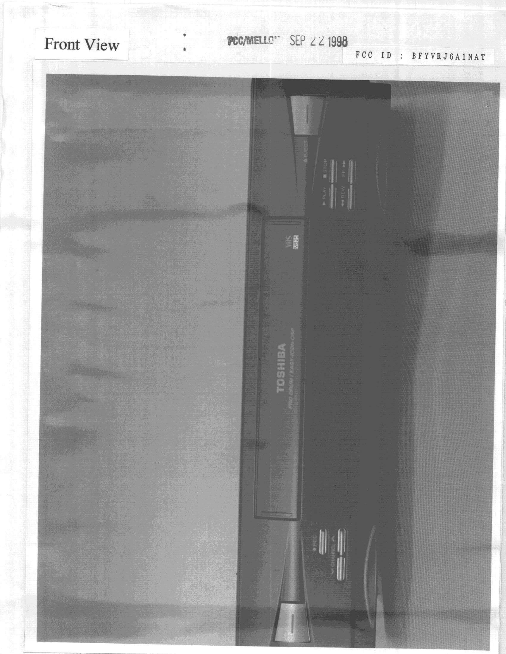
BFYVRJ6A1NAT
Oct 29, 1998Videocassette Recorder
Equipment Class
HID - Part 15 TV Interface Device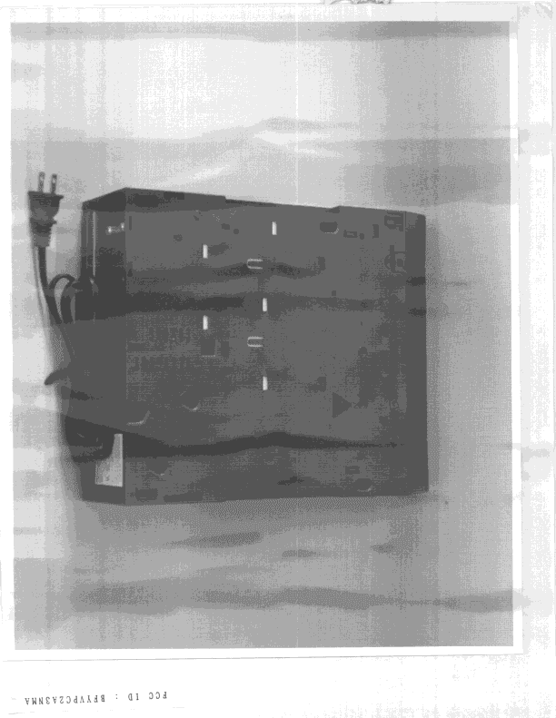
BFYVPC2A3NMA
Sep 23, 1998VCR
Equipment Class
HID - Part 15 TV Interface Device