BGRISM1060BTSinging Machine
Star Light Electronics Co Ltd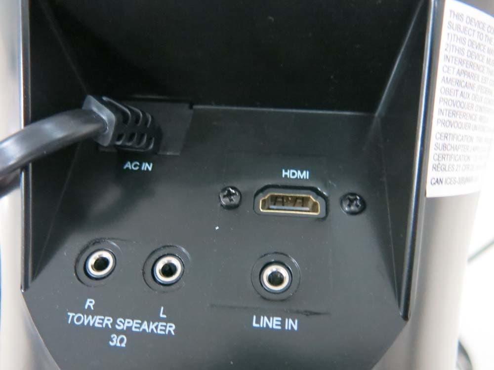
Click to zoom
Application Details
- Equipment Class
- DSS - Part 15 Spread Spectrum Transmitter
- Date of Grant
- Aug 23, 2015
- Application Purpose
- Original Equipment
- Date of Application
- Aug 23, 2015
- Equipment Note
- Singing Machine
- Frequency Range
- 2402.00000000 - 2480.00000000
- Country
- Hong Kong
Documents & Files
Document Text
Text extracted from the exhibit documents filed with the FCC. Open a document above to read the original.
Users Manual
The Singing Machine® is a registered trademark of The Singing Machine Co., Inc. INSTRUCTION MANUAL www.singingmachine.com iSM1060BT 1 Warnings CAUTION: TO REDUCE THE RISK OF ELECTRIC SHOCK, DO NOT REMOVE COVER (OR BACK). NO USER-SERVICEABLE PARTS INSIDE. REFER SERVICING TO QUALIFIED SERVICE PERSONNEL. The Caution marking is located on the bottom panel. CAUTION RISK OF ELECTRIC SHOCK DO NOT OPEN DANGEROUS VOLTAGE:The lightning flash with arrowhead symbol within an equilateral triangle is intended to alert the user to the presence of uninsulated dangerous voltage within the product’s enclosure that may be of sufficient magnitude to constitute a risk of electric shock to persons. CAUTION: TO PREVENT ELECTRIC SHOCK, MATCH WIDE BLADE OF PLUG TO WIDE SLOT AND FULLY INSERT. WARNING:TO PREVENT FIRE OR SHOCK HAZARD, DO NOT EXPOSE THIS UNIT TO RAIN OR MOISTURE. Class II equipment symbol. This symbol indicates that the unit has a double insulation system. ATTENTION:The exclamation point within an equilateral triangle is intended to alert the user to the presence of important operating and maintenance (servicing) instructions in the literature accompanying this product. DANGER:This symbol is intended to alert the user to the risk of exposure to invisible and hazardous laser radiation if the cover or back is opened, the interlock fails or is defeated. Direct exposure to the beam may damage your eyesight. DRIPPING WARNING:This product shall not be exposed to dripping or splashing, and no objects filled with liquids, such as vases, shall be placed on the product. VENTILATION WARNING:The normal ventilation of the product shall not be impeded for intended use. Important Safety Information 1.Read these Instructions. 2. Keep these Instructions. 3. Heed all Warnings. 4. Follow all Instructions. 5. Do not use this apparatus near water. 6. Clean only with a dry cloth. 7. Do not block any of the ventilation openings. Install in accordance with the Manufacturer’s instructions. 8. Do not install near any heat sources such as radiators, heat registers, stoves, or other apparatus (including amplifiers) that produce heat. 9. Do not defeat the safety purpose of the polarized or grounding- type plug. A polarized plug has two blades with one wider than the other. A grounding type plug has two blades and a third grounding prong. The wide blade or the third prong are provided for your safety. When the provided plug does not fit into your outlet, consult an electrician for replacement of the obsolete outlet. 10. Protect the power cord from being walked on or pinched particularly at plugs, convenience receptacles, and the point where they exit from the apparatus. 11. Only use attachments/accessories specified by the manufacturer. 12. Use only with a cart, stand, tripod, bracket, or table specified by the manufacturer, or sold with the apparatus. When a cart is used, use caution when moving the cart/apparatus combination to avoid injury from tip-over. 13. Unplug this apparatus during lightning storms or when unused for long periodsof time. 14. Refer all servicing to qualified service personnel. Servicing is required when the apparatus has been damaged in any way, such as power-supply cord or plug is damaged, liquid has been spilled or objects have fallen into the apparatus, the apparatus has been exposed to rain or moisture, does not operate normally, or has been dropped. 15. WARNING: To reduce the risk of fire or electric shock, do not expose this apparatus to rain or moisture. Do not place objects filled with water, such as a vase, on the apparatus. 16. The AC mains plug is used as the power disconnect device and it should remain readily accessible and operable during intended use. In order to completely disconnect the apparatus from power, the mains plug should be completely removed from the AC outlet socket. 17. CAUTION: To reduce the risk of fire or explosion, do not expose batteries to excessive heat such as sunshine, fire or other heat sources. FCC Statement This device complies with part 15 of the FCC Rules. Operation is subject to the following two conditions: (1) This device may not cause harmful interference, and (2) this device must accept any interference received, including interference that may cause undesired operation. Any Changes or modifications not expressly approved by the party responsible for compliance could void the user's authority to operate the equipment. Note: This equipment has been tested and found to comply with the limits for a Class B digital device, pursuant to part 15 of the FCC Rules. These limits are designed to provide reasonable protection against harmful interference in a residential installation. This equipment generates uses and can radiate radio frequency energy and, if not installed and used in accordance with the instructions, may cause harmful interference to radio communications. However, there is no guarantee that interference will not occur in a particular installation. If this equipment does cause harmful interference to radio or television reception, which can be determined by turning the equipment off and on, the user is encouraged to try to correct the interference by one or more of the following measures: -Reorient or relocate the receiving antenna. -Increase the separation between the equipment and receiver. -Connect the equipment into an outlet on a circuit different from that to which the receiver is connected. -Consult the dealer or an experienced radio/TV technician for help. This device complies with Industry Canada licence-exempt RSS standard(s). Operation is subject to the following two conditions: (1) This device may not cause interference, and (2) This device must accept any interference, including interference that may cause undesired operation of the device. This equipment should be installed and operated with a minumum distance of 20 cm between the radiator and your body. Le présentappareilestconforme aux CNR d'Industrie Canada applicables aux appareils ra…
Text truncated - open the document above for the full version.
Cover Letter(s)
Declaration on model difference Page 1 of 1 We the undersigned hereby confirm that these models are same, and all models have the same RF module and antenna, the only differences are appearance and model no. for trading purpose. Productio n name Trade name FCC ID INPUT Model no. Singing Machine N/A BGRISM1060BT AC 120V, 60Hz iSM1060BT, iSM1020BT, iSM1040BT, iSM1020BTXY, iSM1040BTXY, iSM1060BTXY (The combination of XY means unit color. X can be A to Z or blank & Y can be A to Z or blank) Confirmed by: Date: 2015-08-19
Cover Letter(s)
Date: 2015-08-21 To: Federal Communications Commission 7435 Oakland Mills Road Columbia, MD FCC ID: BGRISM1060BT To Whom It May Concern: This letter is to ascertain that Star Light Electronics Co. Ltd Product Singing Machine has been the units used for conducting FCC compliance testing, the DoC part will be tested by FCC recognized test lab. If you have any question or concerns, pls. contact us. Sincerely, President 5/F, Shing Dao Industrial Building, 232 Aberdeen Main Road, Aberdeen, Hong Kong
ID Label/Location Info
Label Location on EUT
Internal Photos
Antenna
RF Exposure Info
RF EXPOSURE EVALUATION According to FCC 1.1310: The criteria listed in the following table shall be used to evaluate the environment impact of human exposure to radio frequency(RF) Radiation as specified in §1.1307(b) FCC ID:BGRISM1060BT EUT Specification EUT Singing Machine Frequency band (Operating) WLAN: 2.412GHz ~ 2.462GHz WLAN: 5.18GHz ~ 5.32GHz / 5.50GHz ~ 5.70GHz WLAN: 5.745GHz ~ 5825GHz Others Device category Portable (<20cm separation) Mobile (>20cm separation) Others ___ Exposure classification Occupational/Controlled exposure (S = 5mW/cm2) General Population/Uncontrolled exposure (S=1mW/cm2) Antenna diversity Single antenna Multiple antennas Tx diversity Rx diversity Tx/Rx diversity Max. output power -0.84dBm(0.000824W) Antenna gain (Max) -0.68 dBi Evaluation applied MPE Evaluation SAR Evaluation Limits for Maximum Permissible Exposure(MPE) Frequency Range(MHz) Electric Field Strength(V/m) Magnetic Field Strength(A/m) Power Density(mW/cm 2 ) Average Time (A) Limits for Occupational/Control Exposures 300-1500 -- -- F/300 6 1500-100000 -- -- 5 6 (B) Limits for General Population/Uncontrol Exposures 300-1500 -- -- F/1500 6 1500-100000 -- -- 1 30 Friis transmission formula: Pd=(Pout*G)\(4*pi*R2) Where Pd= Power density in mW/cm 2 Pout=output power to antenna in Mw G= gain of antenna in linear scale Pi=3.1416 R= distance between observation point and center of the radiator in cm Pd the limit of MPE, 1mW/cm2. If we know the maximum gain of the antenna and total power input to the antenna, through the calculation, we will know the distance where the MPE limit is reached. Measurement Result Channel Frequency (MHz) Measurement Peak Output Power(dBm) GFSK Π/4-DQPSK 2402 -0.84 -1.93 2441 -1.77 -3.04 2480 -2.48 -3.73 Channel Frequency (MHz) Tune up tolerance (dBm) Max tune up conducted power(dBm) Output Peak power (mW) Ant. Gain (dBi) Ant. Gain (nume ric) Power density at 20cm (mW/cm 2 ) Power density Limits (mW/cm 2 ) 2402 -1±1 0 1.00 -0.68 0.855 0.000170 1 2441 -2±1 -1 0.79 -0.68 0.855 0.000135 1 2480 -3±1 -2 0.63 -0.68 0.855 0.000107 1 2402 -2±1 -1 0.79 -0.68 0.855 0.000135 1 2441 -3±1 -2 0.63 -0.68 0.855 0.000107 1 2480 -4±1 -3 0.50 -0.68 0.855 0.000085 1 Signature Date: 2015-08-19
Test Report
TRF No. FCC Part 15.247/A Page 1 of 66 Report No. KAD150630100E Ver.1.0 ELECTROMAGNETIC EMISSIONS COMPLIANCE REPORT INTENTIONAL RADIATOR CERTIFICATION TO FCC PART 15 SUBPART C REQUIREMENT OF Singing Machine Model No.: iSM1060BT, iSM1020BT, iSM1040BT, iSM1020BTXY, iSM1040BTXY, iSM1060BTXY (The combination of XY means unit color. X can be A to Z or blank & Y can be A to Z or blank) Trademark: N/A FCC ID: BGRISM1060BT Report No.: KAD150630100E Issue Date: August 19, 2015 Prepared for Star Light Electronics Co. Ltd 5/F, Shing Dao Industrial Building, 232 Aberdeen Main Road, Aberdeen, Hong Kong Prepared by DONGGUAN EMTEK CO., LTD. No.281, Guantai Road, Nancheng District, Dongguan, Guangdong, China TEL: 86-769-22807078 FAX: 86-769-22807079 This report shall not be reproduced, except in full, without the written approval of DONGGUAN EMTEK CO., LTD. TRF No. FCC Part 15.247/A Page 2 of 66 Report No. KAD150630100E Ver.1.0 VERIFICATION OF COMPLIANCE Applicant: Star Light Electronics Co. Ltd 5/F, Shing Dao Industrial Building, 232 Aberdeen Main Road, Aberdeen, Hong Kong Manufacturer: Star Light Electronics Co. Ltd 5/F, Shing Dao Industrial Building, 232 Aberdeen Main Road, Aberdeen, Hong Kong Product Description: Singing Machine Trade Mark: N/A Model Number: iSM1060BT, iSM1020BT, iSM1040BT, iSM1020BTXY, iSM1040BTXY, iSM1060BTXY (The combination of XY means unit color. X can be A to Z or blank & Y can be A to Z or blank) (Note: The samples are the same except appearance and model number. So iSM1060BT was selected for full test.) We hereby certify that: The above equipment was tested by DONGGUAN EMTEK CO., LTD. The test data, data evaluation, test procedures, and equipment configurations shown in this report were made in accordance with the procedures given in ANSI C63.10-2013 and the energy emitted by the sample EUT tested as described in this report is in compliance with conducted and radiated emission limits of FCC Rules Part 15.247(2014). Date of Test : June 30, 2015 to August 05, 2015 Prepared by : Ivy Huang/Editor Reviewer : Alan He/Supervisor Approved & Authorized Signer : Sam Lv/Manager TRF No. FCC Part 15.247/A Page 3 of 66 Report No. KAD150630100E Ver.1.0 Modified Information Version Summary Revision Date Report No. Ver.1.0 Original Report / KAD150630100E TRF No. FCC Part 15.247/A Page 4 of 66 Report No. KAD150630100E Ver.1.0 Table of Contents 1. GENERAL INFORMATION ................................................................................................ 6 1.1 PRODUCT DESCRIPTION ................................................................................................................... 6 1.2 TEST FACILITY ................................................................................................................................. 7 2. SYSTEM TEST CONFIGURATION .................................................................................... 8 2.1 EUT CONFIGURATION ...................................................................................................................... 8 2.2 EUT EXERCISE ................................................................................................................................ 8 2.3 TEST PROCEDURE ........................................................................................................................... 8 2.4 CONFIGURATION OF TESTED SYSTEM .............................................................................................. 9 3. SUMMARY OF TEST RESULTS ..................................................................................... 10 4. DESCRIPTION OF TEST MODES ................................................................................... 11 5. TEST SYSTEM UNCERTAINTY ...................................................................................... 12 6. CONDUCTED EMISSIONS TEST .................................................................................... 13 6.1 MEASUREMENT PROCEDURE: ........................................................................................................ 13 6.2 TEST SET-UP (BLOCK DIAGRAM OF CONFIGURATION) ................................................................... 13 6.3 MEASUREMENT EQUIPMENT USED: ................................................................................................ 13 6.4 MEASUREMENT RESULT: ................................................................................................................ 13 6.5 CONDUCTED MEASUREMENT PHOTOS: .......................................................................................... 16 7. RADIATED EMISSION TEST ........................................................................................... 17 7.1 MEASUREMENT PROCEDURE ......................................................................................................... 17 7.2 TEST SET-UP (BLOCK DIAGRAM OF CONFIGURATION) ................................................................... 18 7.3 MEASUREMENT EQUIPMENT USED: ................................................................................................ 19 7.4 RADIATED EMISSION LIMIT ............................................................................................................. 20 7.5 MEASUREMENT RESULT ................................................................................................................. 21 7.5 RADIATED MEASUREMENT PHOTOS: .............................................................................................. 31 8. CHANNEL SEPARATION TEST ...................................................................................... 32 8.1 MEASUREMENT PROCEDURE ......................................................................................................... 32 8.2 TEST SET-UP (BLOCK DIAGRAM OF CONFIGURATION) ................................................................... 32 8.3 MEASUREMENT EQUIPMENT USED: ............................................................................…
Text truncated - open the document above for the full version.
Contact Information
Applicant
Jacky Lau(President)
Test Firm
EMTEK (DONGGUAN) CO.,LTDSam Lv
Technical Specifications
| # | Rule Parts | Frequency Range | Power Output |
|---|---|---|---|
| 1 | 15C | 2.40 GHz - 2.48 GHz | 824.00 µW |
Other Applications from Star Light Electronics Co Ltd
BGRISM1050BT
Jul 30, 2013Pedestal Karaoke System
Equipment Class
DSS - Part 15 Spread Spectrum Transmitter
BGRSMI440BT
Jul 24, 2013Outdoor BT Speaker
Equipment Class
DSS - Part 15 Spread Spectrum Transmitter
BGRTL-9008
Oct 05, 1998900 MHz Cordless Phone
Equipment Class
DXT - Part 15 Low Power Transceiver, Rx Verified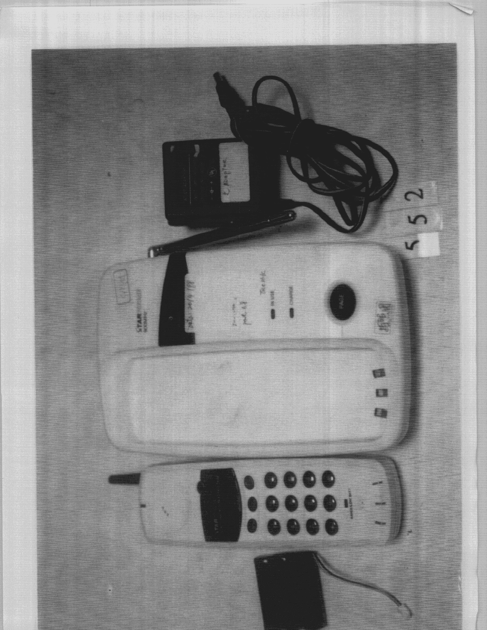
BGRTL-2900
Sep 23, 1998Cordless Phone
Equipment Class
DSS - Part 15 Spread Spectrum TransmitterBGR9JRTL-6908
Dec 22, 1997ETS - Part 15 Cordless Telephone System
Equipment Class
ETS - Part 15 Cordless Telephone System