BKMAEWN7512Wireless LAN 802.11 b/g/n adapter
Seiko Epson Corporation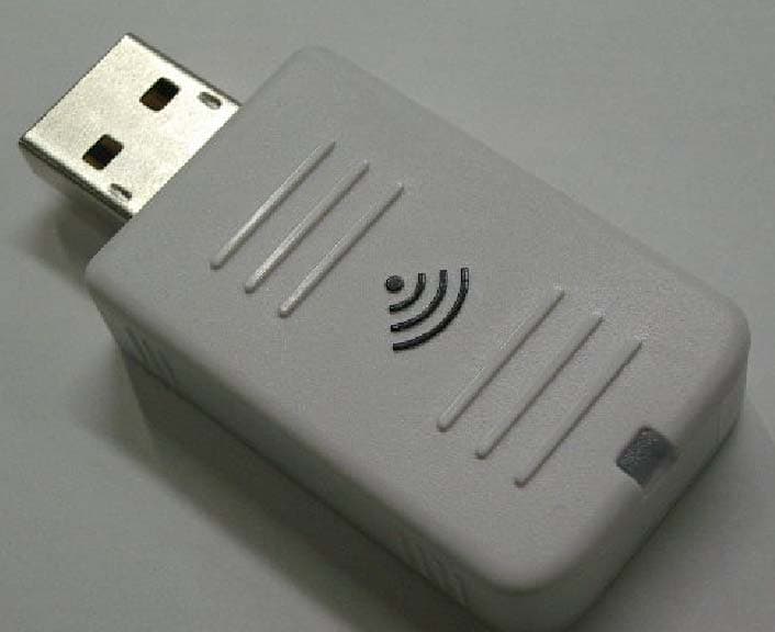
Click to zoom
Application Details
- Equipment Class
- DTS - Digital Transmission System
- Date of Grant
- Jun 01, 2010
- Application Purpose
- Original Equipment
- Date of Application
- Jun 01, 2010
- Equipment Note
- Wireless LAN 802.11 b/g/n adapter
- Frequency Range
- 2412.00000000 - 2462.00000000
- Company
- Seiko Epson Corporation
- Country
- Japan
Documents & Files
Document Text
Text extracted from the exhibit documents filed with the FCC. Open a document above to read the original.
Users Manual
1 ELPAP0 7 Wireless LAN unitUser's Guide 2 Notations Used in This Guidef General information indications Attention Indicates procedures which may result in damage or injury if sufficient care is not taken. q Indicates additional information and points which may be useful to know regarding a topic. s Indicates a page where detailed information regarding a topic can be found.Indicates operating methods and the order of operations.The procedure indicated should be carried out in the order of the numbered steps. [ (Name) ] Indicates the name of the buttons on the remote control or the control panel.Example: [Esc] button "(Menu Name)" Indicates configuration menu items.Example: "Image" - "Brightness" Procedure 3 Supplied Items ListSee the following check lis t to make sure that you have all of the supplied items. If anything is missing or damaged, please contact your dealer. Wireless LAN unit Screw (plus head screw M2 ^ 8) Document CD-ROM (This Guide) 4 Safety InstructionsThank you very much for purchasing this product. Read this document carefully to use this unit safely and correctly. To allow you to solve any unknown points quickly, keep this information close to hand.So that you can use the product safely and correctly, symbols are applied in the documentation and on the product to indicate possible harm to the user or to others and the risk of damage to property. The indications and their meaning are as follows. Make sure you understand them properly before reading the guide. Warning This symbol indicates information that, if ignored, could possibly result in death or personal injury due to incorrect handling. Caution This symbol indicates information that, if ignored, could possibly result in personal injury or physical damage due to incorrect handling. Warning • May exert electromagnetic interference on, and cause malfunction of, cardiac pacemakers. Before use, ensure that electromagnetic interference does not occur. • May exert electromagnetic interference on, and cause malfunction of, sensitive medical equipment. Before use, ensure that electromagnetic interference does not occur. • Use of this product on aircraft may be restricted in some countries. Use of this product is based on due diligence with regard to regulations. Caution • This unit should only be used for Epson projectors. If it is installed on another device such as a computer, it may result in computer failure, damage, or malfunctions. • Do not disassemble or remodel this unit. This may result in burns. 5 PrecautionsNotes on Handling and Storage • Do not store in locations with high temperatures or high humidity. It may in particular be dama ged or deformed if left in a vehicle with the windows shut, or placed it locations with unusually high temperatures for extended periods such as in direct sunlight. • Do not get it wet. This may cause malfunctions to occur.• Do not use near microwave ovens. Wireless communication may be interrupted by electromagnetic in terference generated by microwave ovens. • Do not drop it, subject it to shocks, or place heavy objects on it. Frequency Precautions The frequency band for this unit is 2.4 GHz/5 GHz. This frequency range is the same frequency bandwidth as industrial, scientific, and medical devices such as microwave ovens a nd mobile unit identification (RF-ID) systems (licensed premises radio st ations and unlicensed specified low- power radio stations) used in factor y production lines. Before using this unit, check that there are no radio stations for mobile unit identification or specified low-power radio station premises nearby. In the event that this unit should interfere electromagnetically with the premises of a radio station used for mobile unit rec ognition, cease use immediately and stop generating the electromagnetic field. Contact your local dealer or the nearest address provided in the Suppor t and Service Guide supplied with the projector if this unit interferes el ectromagnetically with a special low- power radio station used for mobile unit identification or causes similar problems. Wireless Telegraphy Act Regulations The following acts are prohibited by the Wireless Telegraphy Act.• Modifying and disassembling (including the antenna)• Removing the label of conformance• IEEE 802.11a (5 GHz band) external use International Travel Precautions Wireless devices are designed to conf orm to the channel and frequency limits of the country they are intended to be used in. This unit is based on the specifications of the country of sa le. If this unit is used outside the country of sale, check with a local dealer for more information. Precautions 6 Notes on Security when Using Wireless LAN (Important information on customer rights (maintaining privacy))The advantage of using a wireless LAN over a LAN cable is that, because information is exchanged using radio signals, you can easily connect to the network if you are within range of the radio signals. A disadvantage of this is that within a certain range , the electromagnetic signals can pass through barriers such as walls, so that if security countermeasures are not implemented in some way, problems such as the following may occur.• Communicated data can be intercepted A third party may be able to rece ive wireless transmissions without authorization, and they could obtain personal information from these transmissions such as IDs, passwords, or credit card numbers, or they could intercept the contents of personal e-mail messages. • Unauthorized access to the network A third party could access an individual or intra-company network without permission and carry out any of the following activities.- Retrieve personal data or other secret information (information leakage) - Pose as another user and send inappropriate data (impersonation) - Overwrite the contents of intercep ted data and resend it (falsification) - Introduce a computer virus which could cause data loss or system crashes (damage) Initially, the possibility tha…
Text truncated - open the document above for the full version.
External Photos
External Photo Seiko Epson Corporation Wireless LAN 802.11b/g/n adapter [Model: WN7512BEP] Front Back External Photo Seiko Epson Corporation Wireless LAN 802.11b/g/n adapter [Model: WN7512BEP] Right Left External Photo Seiko Epson Corporation Wireless LAN 802.11b/g/n adapter [Model: WN7512BEP] Top Bottom
ID Label/Location Info
Label estimate location UL Label
Internal Photos
Internal Photo Seiko Epson Corporation Wireless LAN 802.11b/g/n adapter [Model: WN7512BEP] Internal Photo Seiko Epson Corporation Wireless LAN 802.11b/g/n adapter [Model: WN7512BEP] Internal Photo Seiko Epson Corporation Wireless LAN 802.11b/g/n adapter [Model: WN7512BEP] Internal Photo Seiko Epson Corporation Wireless LAN 802.11b/g/n adapter [Model: WN7512BEP] Internal Photo Seiko Epson Corporation Wireless LAN 802.11b/g/n adapter [Model: WN7512BEP] Internal Photo Seiko Epson Corporation Wireless LAN 802.11b/g/n adapter [Model: WN7512BEP]
RF Exposure Info
UL Japan, Inc. Head Office EMC Lab. 4383-326 Asama-cho, Ise-shi, Mie-ken 516-0021 JAPAN Telephone : +81 596 24 8116 Facsimile : +81 596 24 8124 Applicant: Seiko Epson Corporation Type of Equipment : Wireless LAN 802.11b/g/n adapter Model No. : WN7512BEP FCC ID: BKMAEWN7512 IC Number:1052D-WN7512 Seiko Epson Corporation declares that Model : WN7512BEP ⇒ complies with FCC radiation exposure requirement specified in the FCC Rules 2.1091 (for mobile). RF Exposure Calculations: ← The following information provides the minimum separation distance for the highest gain antenna provided with the “WN7512BEP“ as calculate d from FCC OET Bulletin 65 Appendix A, Table (B) Limits for General Population / Uncontrolled Exposure. This calculation is based on the highest EIRP possible from the system, considering maximum power and antenna gain, and considering a 1.0mW/cm^2 uncontrolled exposure limit. The Friis formula used was: S = (P * G) / (4* π * r 2 ) Where P = 309.74 mW (Maximum peak output power) G = 1.00 Numerical Antenna gain; equal to0.00dBi r =20.0 cm For: WN7512BEPS =0.06162 mW/cm 2 No. : 30GE0203-HO-02 RF Exposure / MPE Calculation
Test Report
Test report No. : 30GE0203-HO-02-A-R5 Page : 2 of 57 Issued date : March 26, 2010 Revised date : May 27, 2010 FCC ID : BKMAEWN7512 UL Japan, Inc. Head Office EMC Lab. 4383-326 Asama-cho, Ise-shi, Mie-ken 516-0021 JAPAN Telephone : +81 596 24 8116 Facsimile : +81 596 24 8124 CONTENTS PAGE SECTION 1: Customer information.........................................................................................................3 SECTION 2: Equipment under test (E.U.T.)...........................................................................................3 SECTION 3: Test specification, procedures & results............................................................................4 SECTION 4: Operation of E.U.T. during testing ....................................................................................8 SECTION 5: Conducted Emission..........................................................................................................10 SECTION 6: Radiated Spurious Emission ............................................................................................11 SECTION 7: Antenna Terminal Conducted Tests................................................................................12 APPENDIX 1: Photographs of test setup ...............................................................................................13 Conducted Emission .........................................................................................................................13 Radiated Spurious Emission .............................................................................................................14 Worst Case Position (Horizontal: X-axis/ Vertical:X-axis) ..............................................................15 APPENDIX 2: Data of EMI test..............................................................................................................16 Conducted Emission .........................................................................................................................16 6dB Bandwidth .................................................................................................................................23 Maximum Peak Output Power ..........................................................................................................26 Radiated Spurious Emission .............................................................................................................29 Conducted Spurious Emission ..........................................................................................................40 Conducted Emission Band Edge compliance ...................................................................................50 Power Density ...................................................................................................................................51 99%Occupied Bandwidth .................................................................................................................55 APPENDIX 3: Test instruments .............................................................................................................57 Test report No. : 30GE0203-HO-02-A-R5 Page : 3 of 57 Issued date : March 26, 2010 Revised date : May 27, 2010 FCC ID : BKMAEWN7512 UL Japan, Inc. Head Office EMC Lab. 4383-326 Asama-cho, Ise-shi, Mie-ken 516-0021 JAPAN Telephone : +81 596 24 8116 Facsimile : +81 596 24 8124 SECTION 1: Customer information Company Name : Seiko Epson Corporation Address : 4897 Shimauchi, Matsumoto-shi, Nagano-ken 390-8640, Japan Telephone Number : +81-263-48-5014 Facsimile Number : +81-263-48-0583 Contact Person : Hiroshi Harima SECTION 2: Equipment under test (E.U.T.) 2.1 Identification of E.U.T. Type of Equipment : Wireless LAN 802.11b/g/n adapter Model No. : WN7512BEP Serial No. : Refer to Section 4, Clause 4.2 Receipt Date of Sample : March 10, 2010 Country of Mass-production : China Condition of EUT : Production prototype (Not for Sale: This sample is equivalent to mass-produced items.) Modification of EUT : No Modification by the test lab 2.2 Product Description General Specification Feature of EUT : EUT is an adapter attached to the projector to communicate on 2.4GHz band, which does not have HT40 and channel bonding function. North America specifications: 1-11ch Clock frequency(ies) in the system : 40MHz Power Supply : DC5.0V Radio Specification Radio Type : Transceiver Frequency of Operation : 2412-2462MHz Method of Frequency Generation : Crystal Power Supply (radio part input) : DC 3.3V, DC1.5V Antenna Type : PCB Printed Antenna Antenna Gain : 0 dBi Test report No. : 30GE0203-HO-02-A-R5 Page : 4 of 57 Issued date : March 26, 2010 Revised date : May 27, 2010 FCC ID : BKMAEWN7512 UL Japan, Inc. Head Office EMC Lab. 4383-326 Asama-cho, Ise-shi, Mie-ken 516-0021 JAPAN Telephone : +81 596 24 8116 Facsimile : +81 596 24 8124 SECTION 3: Test specification, procedures & results 3.1 Test Specification Test Specification : FCC Part15 Subpart C: 2010, final revised on January 22, 2010 and effective March 1, 2010 Title : FCC 47CFR Part15 Radio Frequency Device Subpart C Intentional Radiators Section 15.207 Conducted limits Section 15.247 Operation within the bands 902-928MHz, 2400-2483.5MHz, and 5725-5850MHz Test report No. : 30GE0203-HO-02-A-R5 Page : 5 of 57 Issued date : March 26, 2010 Revised date : May 27, 2010 FCC ID : BKMAEWN7512 UL Japan, Inc. Head Office EMC Lab. 4383-326 Asama-cho, Ise-shi, Mie-ken 516-0021 JAPAN Telephone : +81 596 24 8116 Facsimile : +81 596 24 8124 3.2 Procedures and results Item Test Procedure Specification Worst margin Results Remarks FCC: ANSI C63.4:2003 7. AC powerline Conducted Emission measurements FCC: Section 15.207 Conducted Emission IC: RSS-Gen 7.2.2 IC: RSS-Gen 7.2.2 QP 20.3dB, 0.19569MHz, N AV 15.1dB, 0.45522MHz, N Complied - FCC: "Guidance on Measurement of Digital Transmission Systems Operating under Section15.247" FCC: Section 15.247(a)(2) 6dB Bandwidth IC: RSS-Gen 4.6.2 I…
Text truncated - open the document above for the full version.
Test Setup Photos
Test report No. : 30GE0203-HO-02-A-R5 Page : 13 of 57 Issued date : March 26, 2010 Revised date : May 27, 2010 FCC ID : BKMAEWN7512 UL Japan, Inc. Head Office EMC Lab. 4383-326 Asama-cho, Ise-shi, Mie-ken 516-0021 JAPAN Telephone : +81 596 24 8116 Facsimile : +81 596 24 8124 APPENDIX 1: Photographs of test setup Conducted Emission Photo 1 Photo 2 Test report No. : 30GE0203-HO-02-A-R5 Page : 14 of 57 Issued date : March 26, 2010 Revised date : May 27, 2010 FCC ID : BKMAEWN7512 UL Japan, Inc. Head Office EMC Lab. 4383-326 Asama-cho, Ise-shi, Mie-ken 516-0021 JAPAN Telephone : +81 596 24 8116 Facsimile : +81 596 24 8124 Radiated Spurious Emission Photo 1 Photo 2 Test report No. : 30GE0203-HO-02-A-R5 Page : 15 of 57 Issued date : March 26, 2010 Revised date : May 27, 2010 FCC ID : BKMAEWN7512 UL Japan, Inc. Head Office EMC Lab. 4383-326 Asama-cho, Ise-shi, Mie-ken 516-0021 JAPAN Telephone : +81 596 24 8116 Facsimile : +81 596 24 8124 Worst Case Position (Horizontal: X-axis/ Vertical:X-axis) X-axis Y-axis Z-axis
Contact Information
Applicant
Yoshinobu Murakami(CS/Quality Assurance Department)
Technical Contact
UL Japan IncTakahiro Hatakeda
81-596-24-8116
4383-326 Asama-cho · Ise-shi, Mie-ken · Japan
Test Firm
UL Japan, IncMitsuru Fujimura
Technical Specifications
| # | Rule Parts | Frequency Range | Power Output |
|---|---|---|---|
| 1 | 15C | 2.41 GHz - 2.46 GHz | 309.74 mW |
Other Applications from Seiko Epson Corporation
BKMAE-N37663U02
Jul 17, 2024WLAN BT Module
Equipment Class
NII - Unlicensed National Information Infrastructure TX
BKMAE-DTP9757
Mar 04, 2023Streaming Media Player
Equipment Class
DSS - Part 15 Spread Spectrum Transmitter
BKMAE-WH55B
Jul 18, 2022REMOTE CONTROLLER
Equipment Class
DTS - Digital Transmission System
BKMAE-WH5674B
Jul 17, 2022REMOTE CONTROLLER
Equipment Class
DTS - Digital Transmission System
BKMFBM381A
Jul 10, 2022Printer
Equipment Class
NII - Unlicensed National Information Infrastructure TX