BKMFBM224ABluetooth Interface board for Printer
Seiko Epson Corporation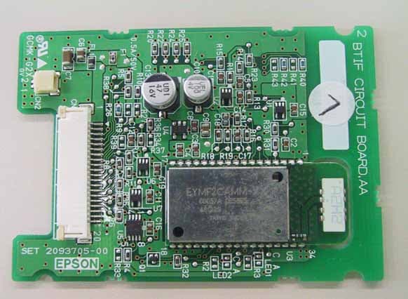
Click to zoom
Application Details
- Equipment Class
- DSS - Part 15 Spread Spectrum Transmitter
- Date of Grant
- Jun 29, 2005
- Application Purpose
- Original Equipment
- Date of Application
- Jun 29, 2005
- Equipment Note
- Bluetooth Interface board for Printer
- Frequency Range
- 2402.00000000 - 2480.00000000
- Company
- Seiko Epson Corporation
- Country
- Japan
Documents & Files
Document Text
Text extracted from the exhibit documents filed with the FCC. Open a document above to read the original.
Users Manual
Users Manual Model No. : M224A FCC ID : BKMFBM224A SEIKO EPSON CORPORATION Equipment Description: M224A is the interface board connects Bluetooth module and the Printer. M224A contains “CN1”, I/O connector for the Printer, and “EYMF2CAMM-YV”, Bluetooth Module made by Taiyo Yuden Co., Ltd. Model Name: M224A EYMF2CAMM-YV Cable CN1 M224A Device <CAUTION> * The following sentence has to be displayed on the outside of the device in which the module is installed: “Contains Transmitter Module FCC ID: BKMFBM224A”, or “Contains FCC ID: BKMFBM224A” * Please note that this users manual (installation instruction) should no be provided to end-users. How to Built - In: Device M224A EYMF2CAMM-YV MOLEX 20.1MM, UL-R:CN1 EYMF2CAMM-YV M224A Device Connect *Please prepare the cable complied with CN1. This document consists of 2 parts. <Part 1> Pin Description of Connector (CN1) for M224 <Part 2> Users Manual for “EYMF2CAMM-YV” <Part 1> <Part 2> 殿 No.HD-SH-GT02224-A 受付 041102 New Change 新規・変更 User’s Manual ユーザーズマニュアル Module name 品名 EYMF2CAMM-YV 領印欄 We hereby the specification. この書類の内容を確認し受領致しました。 Received by 〈御受領印〉 DATE: . . DATE: Submitted by TAIYO YUDEN Co.,Ltd. 太陽誘電株式会社 モジュール事業部 無線技術部 APPROVED 品証承認 DES.REVIEW 設計承認 CHECKED 確認 DESIGNED 担当 APPROVEDCHECKER DRAWN DESIGNE Control No. HD-SH- GT02224 (1/2) Control name User’s Manual ユーザーズマニュアル (1)Revision history 改訂経歴 Revision No. 改訂経歴 Designed 担当 Rectification record 変更経歴 Checked 確認 Approved 承認 New document 初版 Newly issued 新規作成 A B C D E F G H J K L M N P Q TAIYO YUDEN Co.,Ltd. APPROVED CHECKER DRAWN DESIGNE Control No. HD-SH- GT02224 (2/2) Control name User’s Manual ユーザーズマニュアル (2)Document constituent list 構成書類リスト Control name 書類名 Control No. 書類番号 Document page 構成ページ General items 一般事項書 HD-AG-A041102 1/6 ~ 6/6 Absolute maximum ratings 絶対最大定格書 HD-AM-A041102 1/1 Outline・Appearance 外形・外観図 HD-AD-A041102 1/3 ~ 2/3 Pin layout ピンレイアウト図 HD-BA-A041102 1/1 Regulatory information 1/1 TAIYO YUDEN Co.,Ltd. APPROVEDCHECKED DRAWN DESIGNED Control No. HD-AG- A041102-A (1/6) Control name General items 一般事項書 (1)Scope 適用 This specification (“Specification”) applies to the hybrid IC “EYMF2CAMM-YV” for use Bluetooth ® module (“Product”) manufactured by TAIYO YUDEN Co.,Ltd. (“TAIYO YUDEN”) 本仕様書は、太陽誘電株式会社(“弊社”)により製造されるBluetooth ® 用ハイブリッドIC ”EYMF2CAMM-YV” (“本製品”)に適用する。 (2)Description 内 容 ① Model name : EYMF2CAMM-YV 型 番 : EYMF2CAMM-YV ② Function: Radio frequency transceiver Module (power class2, Bluetooth ® standard Ver1.1 conformity) 機 能 : 無線通信モジュール(出力Class2、Bluetooth ® 規格Ve r 1 . 1準拠) ③ Application: PDA, Barcode Reader and Pos 用 途 : PDA, Barcode Reader and Pos ④ Structure: Hybrid IC loaded with silicon monolithic semiconductor 構 造 : シリコンモノリシック半導体を用いた混成集積回路 Ability of lead free mounting at customer's assembly (Heat resistance of this Product) :Yes お客様でのPbフリー実装可否(本製品の耐熱性) :可能 Containment of hazardous substance in this Product * RoHS regulation substance(Pb.Cd.Hg.Cr+6.PBB.PBDE) :Non use 本製品内の環境物質含有 * RoHS規制物質(Pb.Cd.Hg.Cr+6.PBB.PBDE) :未使用 ⑤ Outline : 34-pin leadless chip carrier 外 形 : 34ピン リードレスチップキャリア ⑥ Marking : Model name, BD_ADDR, Lot No. and manufacturer on Shielding Case 表 示 : シールドケース上に、品名, BD_ADDR, ロットNo., 製造会社名を印字 ⑦ Notes : その他 : a. Limitation of Warranty 保証 i) TAIYO YUDEN provide warranties only if the Product is operated under the condition set forth in this Specification. Please note that TAIYO YUDEN shall not be liable for any defect and/or malfunction arising from use of the Product under the terms and conditions other than the operating conditions hereof. 本製品の保証使用条件は本仕様書の通りです。 本保証条件以外の条件で御使用になった結果発生した不良・不具合につきましては、弊社 は責任を負い兼ねますので御了承下さい。 The Bluetooth ® word mark and logos are owned by the Bluetooth ® SIG, Inc. and any use of such marks by TAIYO YUDEN CO., LTD. is under license. TAIYO YUDEN Co.,Ltd. APPROVEDCHECKED DRAWN DESIGNED Control No. HD-AG- A041102-A (2/6) Control name General items 一般事項書 ii) This Product is designed for use in products which comply with Bluetooth ® Specifications (Ver.1.1) (“Bluetooth Specifications”). TAIYO YUDEN disclaims and is not responsible for any liability concerning infringement by this Product under any intellectual property right owned by third party in case the customer uses this Product in any product which does not comply with Bluetooth ® Specifications (the “non-complying products”). Furthermore, TAIYO YUDEN warrants only that this Product complies with this Specification and does not grant any other warranty including warranty for application of the non-complying products. 本製品はBluetooth ® の規格(Ver.1.1)に従って製造された製品であり、本製品の用途が Bluetooth ® 規格以外もしくは当該規格に従わない製品(「Bluetooth ® 規格外製品」)への使用 の場合、弊社は第三者の知的財産権の侵害に基づくいかなる責任を負いません。また、弊社 は本製品が本仕様書に準拠することのみを保証するもので、上記Bluetooth ® 規格外製品への 応用についての保証等いかなる保証を行うものではありません。 b. Instruction for Use (CAUTION) 使用上の注意事項 i) Because Product is not designed for radiation durability, please refrain from exposing Product to radiation in the use. 本製品は、耐放射線設計をしておりませんので、放射線のストレスを受ける環境下での使 用は避けて下さい。 ii) Communication between this Product and other might not be established nor maintained depending upon radio environment or operating condition of this Product and other products with Bluetooth ® wireless technology. 本製品と本製品又は他製品の通信は、周囲の電波環境及び機器環境により確立又は維持し 難くなることがあります。 iii) This Product operates in the unlicensed ISM band at 2.4GHz. In case this Product is used around the other wireless devices which operate in same frequency band of this Product, there is a possibility that interference occurs between this Product and such other devices. If such interference occurs, please stop the operation of other devices or relocate this Product before using this Product or do not use this Product around the other wireless devices. 本製品は2.4GHz帯の周波数を使用しています。本製品を本製品と同じ周波数を使用した 他の無線機器の周辺でご使用になりますと、本製品とかかる他の無線機器との間で電波干 渉が発生する可能性があります。電波干渉が発生した場合、他の無線機器を停止するか、 本製品の使用場所を変えるなど電波干渉の生じない環境でご使用下さい。 iv) This Product mentioned in this Specification is manufactured for PDA, Barcode Reader and Pos. Before using this product in any special equipment (such…
Text truncated - open the document above for the full version.
Cover Letter(s)
Modular Approval Request (per DA 00-1407) FCC ID: BKMFBM224A Items to be covered Answer from applicant 1. The modular transmitter must have its own RF shielding. Yes, this module has RF shielding. 2. The modular transmitter must have buffered modulation/data inputs (if such inputs are provided) to ensure that the module will comply with Part 15 requirements under conditions of excessive data rates or over-modulation. Yes, this module has buffered circuit in RFIC for Bluetooth. 3. The modular transmitter must have its own power supply regulation. Yes, this module has power supply regulator. 4. The modular transmitter must comply with the antenna requirements of Section 15.203 and 15.204(c). The antenna must either be permanently attached or employ a “unique” antenna coupler (at all connections between the module and the antenna, including the cable).. Yes, this module use mounted chip antenna only. 5. The modular transmitter must be tested in a stand-alone configuration, i.e., the module must not be inside another device during testing. This is intended to demonstrate that the module is capable of complying with Part 15 emission limits regardless of the device into which it is eventually installed. Yes, this testing is performed by stand-alone configuration. 6. The modular transmitter must be labeled with its own FCC ID number, and, if the FCC ID is not visible when the module is installed inside another device, then the outside of the device into which the module is installed must also display a label referring to the enclosed module. This exterior label can use wording such as the following: “Contains Transmitter Module FCC ID: XYZMODEL1” or “Contains FCC ID: XYZMODEL1.” Any similar wording that expresses the same meaning may be used. The Grantee may either provide such a label, an example of which must be included in the application for equipment authorization, or, must provide adequate instructions along with the module which explain this requirement. In the latter case, a copy of these instructions must be included in the application for equipment authorization. Yes, the label puts on this module. 7. The modular transmitter must comply with any specific rule or operating requirements applicable to the transmitter and the manufacturer must provide adequate instructions along with the module to explain any such requirements. A copy of these instructions must be included in the application for equipment authorization. For example, there are very strict operational and timing requirements that must be met before a transmitter is authorized for operation under Section 15.231. For instance, data transmission is prohibited, except for operation under Section 15.231(e), in which case there are separate field strength level and timing requirements. Compliance with these requirements must be assured. Yes, we provide adequate instructions for users. 8. The modular transmitter must comply with any applicable RF exposure requirements. For example, FCC Rules in Sections 2.1091, 2.1093 and specific Sections of Part 15, including 15.319(i), 15.407(f), 15.253(f) and 15.255(g), require that Unlicensed PCS, UNII and millimeter wave devices perform routine environmental evaluation for RF Exposure to demonstrate compliance. In addition, spread spectrum transmitters operating under Section 15.247 are required to address RF Exposure compliance in accordance with Section 15.247(b)(4). Modular transmitters approved under other Sections of Part 15, when necessary, may also need to address certain RF Exposure concerns, typically by providing specific installation and operating instructions for users, installers and other interested parties to ensure compliance. Yes, this module is evaluated and complies with RF exposure requirements. Note: If compliance with one or more of the numbered requirements, listed above, cannot be demonstrated, it may be possible to obtain a “Limited Modular Approval” (LMA).
External Photos
M224A SEIKO EPSON CORPORATION Bluetooth Interface board for Printer External Photo I. FRONT VIEW (M224A) TAIYO YUDEN EYMF2CAMM-YV II. REAR VIEW (M224A)
ID Label/Location Info
SEIKO EPSON CORPORATION CONFIDENTIAL Page 1 of 1 M224A (Bluetooth Interface board for printer) 1. Label Drawing 2. Layout Label
Internal Photos
M224A SEIKO EPSON CORPORATION Bluetooth Interface board for Printer Internal Photo I. FRONT VIEW (M224A) TAIYO YUDEN EYMF2CAMM-YV EYMF2CAMM-YV without shielded case M224A SEIKO EPSON CORPORATION Bluetooth Interface board for Printer II. REAR VIEW (M224A)
Operational Description
M224A (Bluetooth Interface board for printer) 1. Features 1) Model Number : M224A 2) Equipment description: Bluetooth Interface board for printer 3) Bluetooth ® standard Ver 1.1 conformity (Modulation Type:GFSK) 4) Power Class2(Max 4dBm) Bluetooth Module 5) Designed for EPSON TM series printers 6) With Antenna is provided on board (Antenna Gain(MAX) = 2.044 dBi) 7) Internal baseband clock oscillator 8) Support functions: Serial Port Emulation(Point-To-Point) 9) Bluetooth wireless connection-to-UART bridge function 10) Interface(to printer): UART 11) Ground line is connected to the application for equipment via one of pins of connector 2. Technical Description 2.1 Specification Parameter Description Min Typ Max Units Carrier Frequency 2.402 2.480 GHz Supply Voltage 3.0 3.3 3.6 V RF Output Power Measured in 50 ohm-6 0 4 dBm Rx Sensitivity - -83 -70 dBm Operating Temperature 0 25 50 Degree C Current Consumption Data receiving 35 mA SEIKO EPSON CORPORATION CONFIDENTIAL Page 1 of 2 2.2 Hardware Block Diagram Regulator Flash Memory Loop Filter Balun B.P.F Crystal Antenna 1.8V 3.3V UART RESET CONNECTOR Bluetooth Module GND Bluetooth Interface board IC (BB+SPP) IC (RF) Ground line is connected to the application for equipment via one of pins of connector 2.3 Functional Block Diagram GPIO UART I/F Host Interface Application RFCOMM SDP L2CAP LMP Hardware SEIKO EPSON CORPORATION CONFIDENTIAL Page 2 of 2
Test Report
TEST REPORT Report No. :ICM0508-FCC Page : 2 of 38 Table of Contents 1 TEST REPORT ................................................................................................................................................................... 4 2 GENERAL INFORMATION ................................................................................................................................................ 4 2.1 P RODUCT DESCRIPTION................................................................................................................................................. 4 2.2 S UMMARY OF TEST AND INSPECTION RESULT.................................................................................................................. 5 2.3 T EST METHODOLOGY..................................................................................................................................................... 5 2.4 T EST FACILITY............................................................................................................................................................... 5 3 SYSTEM TEST CONFIGURATION .................................................................................................................................... 6 3.1 J USTIFICATION............................................................................................................................................................... 6 3.2 O PERATING MODES........................................................................................................................................................ 6 3.3 L IST OF ACCESSORIES.................................................................................................................................................... 7 3.4 I NTERFACE CABLES....................................................................................................................................................... 7 3.5 S PECIAL TEST CONDITION.............................................................................................................................................. 7 3.6 E QUIPMENT MODIFICATIONS........................................................................................................................................... 7 3.7 C ONFIGURATION OF TESTED SYSTEM............................................................................................................................. 8 4 ANTENNA REQUIREMENT ............................................................................................................................................... 9 5 AC POWERLINE CONDUCTED EMISSION TEST.......................................................................................................... 10 5.1 T EST SETUP................................................................................................................................................................ 10 5.2 T EST INSTRUMENTATION.............................................................................................................................................. 10 5.3 C ONDUCTED EMISSION CALCULATION........................................................................................................................... 11 5.4 T EST RESULTS............................................................................................................................................................ 12 5.4.1 Transmitting mode ..................................................................................................................................... 12 6 RADIATED EMISSION TEST ........................................................................................................................................... 15 6.1 T EST SETUP................................................................................................................................................................ 15 6.2 R ADIATED EMISSION CALCULATION...............................................................................................................................16 6.3 T EST RESULTS............................................................................................................................................................ 17 6.3.1 Transmitting mode ..................................................................................................................................... 17 7 20DB BANDWIDTH .......................................................................................................................................................... 23 7.1 T EST SETUP................................................................................................................................................................ 23 7.2 T EST INSTRUMENT....................................................................................................................................................... 23 7.3 T EST RESULTS............................................................................................................................................................ 23 8 CARRIER FREQUENCY SEPARATION.......................................................................................................................... 24 8.1 T EST SETUP................................................................................................................................................................ 24 8.2 T EST INSTRUMENT....................................................................................................................................................... 24 8.3 T EST RESULTS............................................................................................................................................................ 24 9 NUMBER OF HOPPING FREQUENCY .......................................................................................…
Text truncated - open the document above for the full version.
Test Setup Photos
M224A SEIKO EPSON CORPORATION Bluetooth Interface board for Printer TESTED CONFIGURATION PICTURES I. Conducted test configuration picture M224A SEIKO EPSON CORPORATION Bluetooth Interface board for Printer II. Radiated test configuration picture
Contact Information
Applicant
Yoshinobu Murakami(CS/Quality Assurance Department)
Technical Contact
Taiyo Yuden Co., Ltd.Jiro Ogiwara
[email protected]+81273608328
5607-2 Nakamuroda Harunamachi · Gunma-Gun Gunma · Japan
Non-Technical Contact
Taiyo Yuden Co., Ltd.Kiyoko Kariya
[email protected]+81273608328
Test Firm
Taiyo Yuden Co., Ltd. EMC CenterKenzo Furuta
Technical Specifications
| # | Rule Parts | Frequency Range | Power Output |
|---|---|---|---|
| 1 | 15C | 2.40 GHz - 2.48 GHz | 900.00 µW |
Other Applications from Seiko Epson Corporation
BKMAE-N37663U02
Jul 17, 2024WLAN BT Module
Equipment Class
NII - Unlicensed National Information Infrastructure TX
BKMAE-DTP9757
Mar 04, 2023Streaming Media Player
Equipment Class
DSS - Part 15 Spread Spectrum Transmitter
BKMAE-WH55B
Jul 18, 2022REMOTE CONTROLLER
Equipment Class
DTS - Digital Transmission System
BKMAE-WH5674B
Jul 17, 2022REMOTE CONTROLLER
Equipment Class
DTS - Digital Transmission System
BKMFBM381A
Jul 10, 2022Printer
Equipment Class
NII - Unlicensed National Information Infrastructure TX