BKMFBM291ABluetooth Interface Board for Mobile Printer
Seiko Epson Corporation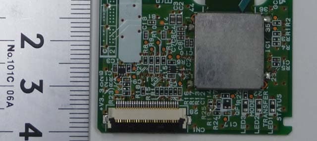
Click to zoom
Application Details
- Equipment Class
- DSS - Part 15 Spread Spectrum Transmitter
- Date of Grant
- Aug 29, 2012
- Application Purpose
- Original Equipment
- Date of Application
- Aug 29, 2012
- Equipment Note
- Bluetooth Interface Board for Mobile Printer
- Frequency Range
- 2402.00000000 - 2480.00000000
- Company
- Seiko Epson Corporation
- Country
- Japan
Documents & Files
Document Text
Text extracted from the exhibit documents filed with the FCC. Open a document above to read the original.
Users Manual
Bluetooth Interface Board User’s Manual 1 Bluetooth Interface Board User’s Manual Features The Bluetooth Interface board has the following features: 1) A built-in Bluetooth module 2) Bluetooth 2.1+EDR compatible 3) Power class: Class 2 4) External dimensions: 40 mm × 43 mm Manufacturer: Seiko Epson Corporation Model Name: M291A Product Name: Bluetooth Interface board for mobile printer Integration to the end product The Bluetooth Interface Board has to be installed and used in accordance with the technical description/installation instructions provided by the manufacturer. The system may only be implemented in the configuration that was authorized. Note that any changes or modifications to this equipment not expressly approved by the manufacturer could void the user’s authority to operate this equipment. Regulatory Information USA-Federal Communications Commission (FCC) This equipment has been tested and found to comply with the limits for a Class B digital device, pursuant to Part 15 of FCC Rules. These limits are designed to provide reasonable protection against harmful interference in a residential installation. This equipment generates, uses, and can radiate radio frequency energy. If not installed and used in accordance with the instructions, it may cause harmful interference to radio communications. However, there is no guarantee that interference will not occur in a particular installation. Bluetooth Interface Board User’s Manual 2 If this equipment does cause harmful interference to radio or television reception, which can be determined by tuning the equipment off and on, the user is encouraged to try and correct the interference by one or more of the following measures: -Reorient or relocate the receiving antenna. -Increase the distance between the equipment and the receiver. -Connect the equipment to outlet on a circuit different from that to which the receiver is connected. -Consult the dealer or an experienced radio/TV technician for help. This device complies with Part 15 of the FCC Rules. Operation is subject to the following two conditions: (1) This device may not cause harmful interference, and (2) This device must accept any interference received, including interference that may cause undesired operation. Any changes or modifications not expressly approved by the party responsible for compliance could void the user’s authority to operate the equipment. Labelling The Bluetooth Interface board labelled as below. FCC ID:BKMFBM291A The proposed FCC ID label format is to be placed on the module. If FCC ID is not visible when the module is installed into the system, “Contains FCC ID: BKMFBM291A” shall be placed on the outside of final host system. Caution: Exposure to Radio Frequency Radiation. To comply with FCC RF exposure compliance requirements, a separation distance of at least 20 cm must be maintained between the antenna of this device and all persons. This device must not be co-located or operating in conjunction with any other antenna or transmitter. Bluetooth Interface Board User’s Manual 3 Canada-Industry Canada (IC) This device complies with RSS 210 of Industry Canada. Operation is subject to the following two conditions: (1) This device may not cause interference, and (2) This device must accept any interference, including interference that may cause undesired operation of this device. L ‘ utilization de ce dispositif est autorisée seulement aux conditions suivantes : (1) il ne doit pas produire de brouillage et (2) l’ utilisateur du dispositif doit étre prêt à accepter tout brouillage radioélectrique reçu, même si ce brouillage est susceptible de compromettre le fomctionnement du dispositif. The term “IC” before the equipment certification number only signifies that the Industry Canada technical specifications were met. Caution: Exposure to Radio Frequency Radiation. To comply with IC RF exposure compliance requirements, a separation distance of at least 20 cm must be maintained between the antenna of this device and all persons. This device must not be co-located or operating in conjunction with any other antenna or transmitter. Instructions to OEM Integrators A User manual provided to the end user must indicate the operating requirements and conditions that must be observed to ensure compliance with the above-mentioned FCC /IC RF Exposure guideline. If this module is intended for use in a portable device, integrators are responsible for separate evaluation and/or approval to satisfy FCC/IC RF Exposure requirements. If other radio devices are to be integrated with this module, an additional evaluation and FCC/IC submission may be required. Integrators are responsible for such additional evaluation and FCC/IC submission.
Cover Letter(s)
Applicant/Grantee Seiko Epson Corporation FCC ID: BKMFBM291A Section 15.212 Modular Transmitters Request for Modular Approval Request for Limited Modular Approval Requirements EUT Conditions Comply (Y/N) Single Modular Approval Requirements 1 The radio elements of the modular transmitter must have their own shielding. The physical crystal and tuning capacitors may be located external to the shielded radio elements. The device is equipped with Metal shielding to cover RF section. Refer to External Photos. Y 2 The modular transmitter must have buffered modulation/data inputs (if such inputs are provided) to ensure that the module will comply with Part 15 requirements under conditions of excessive data rates or over- modulation. All inputs to the device are buffered through logic U1 inputs. Refer to Schematic Diagram. Y 3 The modular transmitter must have its own power supply regulation. The device is equipped with Internal 1.8 V regulator. Refer to Block Diagram. Y 4 The modular transmitter must comply with the antenna and transmission system requirements of Sections 15.203, 15.204(b) and 15.204(c). The antenna must either be permanently attached or employ a “unique” antenna coupler (at all connections between the module and the antenna, including the cable). The “professional installation” provision of Section 15.203 is not applicable to modules but can apply to limited modular approvals under paragraph (b) of this section. The device is equipped with the permanently attached antenna. Any connector isn’t used. Refer to Antenna specification ・ Y 5 The modular transmitter must be tested in a stand-alone configuration, i.e., the module must not be inside another device during testing for compliance with Part 15 requirements. Unless the transmitter module will be battery powered, it must comply with the AC line conducted requirements found in Section 15.207. AC or DC power lines and data input/output lines connected to the module must not contain ferrites, unless they will be marketed with the module (see Section 15.27(a)). The length of these lines shall be the length typical of actual use or, if that length is unknown, at least 10 centimeters to insure that there is no coupling between the case of the module and supporting equipment. Any accessories, peripherals, or support equipment connected to the module during testing shall be unmodified and commercially The device was tested outside of the Laptop PC for full modular approval. Refer to setup photos. Y available (see Section 15.31(i)). 6 The modular transmitter must be equipped with either a permanently affixed label or must be capable of electronically displaying its FCC identification number. (A) If using a permanently affixed label, the modular transmitter must be labeled with its own FCC identification number, and, if the FCC identification number is not visible when the module is installed inside another device, then the outside of the device into which the module is installed must also display a label referring to the enclosed module. This exterior label can use wording such as the following: “Contains Transmitter Module FCC ID: XYZMODEL1” or “Contains FCC ID: XYZMODEL1.” Any similar wording that expresses the same meaning may be used. The Grantee may either provide such a label, an example of which must be included in the application for equipment authorization, or, must provide adequate instructions along with the module which explain this requirement. In the latter case, a copy of these instructions must be included in the application for equipment authorization. (B) If the modular transmitter uses an electronic display of the FCC identification number, the information must be readily accessible and visible on the modular transmitter or on the device in which it is installed. If the module is installed inside another device, then the outside of the device into which the module is installed must display a label referring to the enclosed module. This exterior label can use wording such as the following: “Contains FCC certified transmitter module(s).” Any similar wording that expresses the same meaning may be used. The user manual must include instructions on how to access the electronic display. A copy of these instructions must be included in the application for equipment authorization. The proposed FCC ID label format is to be placed on the module. If FCC ID is not visible when the module is installed into the system, “Contains FCC ID: BKMFBM291A” shall be placed on the outside of final host system. Y 7 The modular transmitter must comply with any specific rules or operating requirements that ordinarily apply to a complete transmitter and the manufacturer must provide adequate instructions along with the module to explain any such requirements. A copy of these instructions must be included in the application for equipment authorization. Refer to “User’s Guide” Exhibit Y 8 The modular transmitter must comply with any applicable RF exposure requirements in its final configuration. The device complies with RF exposure compliance requirement Y A limited modular approval may be granted for single or split modular transmitters that do not comply with all of the above requirements, e.g., shielding, minimum signaling amplitude, buffered modulation/data inputs, or power supply regulation, if the manufacturer can demonstrate by alternative means in the application for equipment authorization that the modular transmitter meets all the applicable Part 15 requirements under the operating conditions in which the transmitter will be used. Limited modular approval also may be granted in those instances where compliance with RF exposure rules is demonstrated only for particular product configurations. The applicant for certification must state how control of the end product into which the module will be installed will be maintained such that full compliance of the end product is always ensured.
External Photos
External Photo Model: M291A <TOP VIEW> <BOTTOM VIEW>
Internal Photos
M291A Internal Photos
Test Report
RTL2610 FCC CFR47 PART 15 SUBPART C INDUSTRY CANADA RSS-210 ISSUE 8 CERTIFICATION TEST REPORT FOR BLUETOOTH INTERFACE BOARD FOR MOBILE PRINTER MODEL NUMBER: M291A FCC ID: BKMFBM291A REPORT NUMBER: 32LE0152-SH-A-R1 ISSUE DATE: AUGUST 27, 2012 Prepared for SEIKO EPSON CORPORATION 3-3-5 Owa Suwa-Shi, Nagano-Ken 392-8502 Japan Prepared by UL Japan, Inc. Shonan EMC Lab. 1-22-3 Megumigaoka, Hiratsuka-shi, Kanagawa-ken 259-1220 JAPAN Telephone number : +81 463 50 6400 Facsimile number : +81 463 50 6401 JAB Accreditation No. : RTL02610 13-EM-F0429 REPORT NO: 32LE152-SH-A-R1 DATE: AUGUST 27, 2012 FCC ID: BKMFBM291A Page 2 of 121 UL Japan, Inc. Shonan EMC Lab. 1-22-3 Megumigaoka, Hiratsuka-shi, Kanagawa-ken, 259-1220 JAPAN TEL: +81 463 50 6400 FAX: +81 463 50 6401 This report shall not be reproduced except in full, without the written approval of UL Japan, Inc. Revision History Rev. Issue Date Revisions Revised By -- 08/06/12 Initial Issue S.Takano 1 08/27/12 Correction of misdescription (limit value) (P34,P69) *This report is a revised version of 32LE0152-SH-A, which is replaced with this report. S.Takano REPORT NO: 32LE152-SH-A-R1 DATE: AUGUST 27, 2012 FCC ID: BKMFBM291A Page 3 of 121 UL Japan, Inc. Shonan EMC Lab. 1-22-3 Megumigaoka, Hiratsuka-shi, Kanagawa-ken, 259-1220 JAPAN TEL: +81 463 50 6400 FAX: +81 463 50 6401 This report shall not be reproduced except in full, without the written approval of UL Japan, Inc. TABLE OF CONTENTS 1. ATTESTATION OF TEST RESULTS ..................................................................................5 2. TEST METHODOLOGY ......................................................................................................6 3. FACILITIES AND ACCREDITATION ..................................................................................6 4. CALIBRATION AND UNCERTAINTY .................................................................................6 4.1. MEASURING INSTRUMENT CALIBRATION ................................................................6 4.2. SAMPLE CALCULATION ..............................................................................................6 4.3. MEASUREMENT UNCERTAINTY.................................................................................6 5. EQUIPMENT UNDER TEST ................................................................................................7 5.1. DESCRIPTION OF EUT ................................................................................................7 5.2. MAXIMUM OUTPUT POWER .......................................................................................7 5.3. DESCRIPTION OF AVAILABLE ANTENNAS ................................................................7 5.4. SOFTWARE AND FIRMWARE .....................................................................................7 5.5. WORST-CASE CONFIGURATION AND MODE ............................................................8 5.6. DESCRIPTION OF TEST SETUP .................................................................................9 6. TEST AND MEASUREMENT EQUIPMENT ......................................................................11 7. ANTENNA PORT TEST RESULTS ...................................................................................13 7.1. BASIC DATA RATE GFSK MODULATION ..................................................................13 7.1.1. 20 dB AND 99% BANDWIDTH .............................................................................13 7.1.2. HOPPING FREQUENCY SEPARATION ..............................................................20 7.1.3. NUMBER OF HOPPING CHANNELS ...................................................................22 7.1.4. AVERAGE TIME OF OCCUPANCY .....................................................................27 7.1.5. MAXIMUM PEAK OUTPUT POWER ....................................................................34 7.1.6. AVERAGE POWER ..............................................................................................35 7.1.7. CONDUCTED SPURIOUS EMISSIONS ...............................................................36 7.2. ENHANCED DATA RATE 8PSK MODULATION .........................................................48 7.2.1. 20 dB AND 99% BANDWIDTH .............................................................................48 7.2.2. HOPPING FREQUENCY SEPARATION ..............................................................55 7.2.3. NUMBER OF HOPPING CHANNELS ...................................................................57 7.2.4. AVERAGE TIME OF OCCUPANCY .....................................................................62 7.2.5. MAXIMUM PEAK OUTPUT POWER ....................................................................69 7.2.6. AVERAGE POWER ..............................................................................................70 7.2.7. CONDUCTED SPURIOUS EMISSIONS ...............................................................71 8. RADIATED TEST RESULTS .............................................................................................83 8.1. LIMITS AND PROCEDURE .........................................................................................83 REPORT NO: 32LE152-SH-A-R1 DATE: AUGUST 27, 2012 FCC ID: BKMFBM291A Page 4 of 121 UL Japan, Inc. Shonan EMC Lab. 1-22-3 Megumigaoka, Hiratsuka-shi, Kanagawa-ken, 259-1220 JAPAN TEL: +81 463 50 6400 FAX: +81 463 50 6401 This report shall not be reproduced except in full, without the written approval of UL Japan, Inc. 8.2. TRANSMITTER ABOVE 1 GHz ...................................................................................84 8.2.1. BASIC DATA RATE GFSK MODULATION ...........................................................84 8.2.2. ENHANCED DATA RATE 8PSK MODULATION ..................................................96 8.3. WORST-CASE BELOW 1 GHz ................................................................................. 108 9. AC POWER LINE CONDUCTED EMISSIONS ................…
Text truncated - open the document above for the full version.
Test Setup Photos
REPORT NO: 32LE152-SH-A-R1 DATE: AUGUST 27, 2012 FCC ID: BKMFBM291A Page 118 of 121 UL Japan, Inc. Shonan EMC Lab. 1-22-3 Megumigaoka, Hiratsuka-shi, Kanagawa-ken, 259-1220 JAPAN TEL: +81 463 50 6400 FAX: +81 463 50 6401 This report shall not be reproduced except in full, without the written approval of UL Japan, Inc. 11. SETUP PHOTOS ANTENNA PORT CONDUCTED RF MEASUREMENT SETUP ANTENNA PORT CONDUCTED PHOTO REPORT NO: 32LE152-SH-A-R1 DATE: AUGUST 27, 2012 FCC ID: BKMFBM291A Page 119 of 121 UL Japan, Inc. Shonan EMC Lab. 1-22-3 Megumigaoka, Hiratsuka-shi, Kanagawa-ken, 259-1220 JAPAN TEL: +81 463 50 6400 FAX: +81 463 50 6401 This report shall not be reproduced except in full, without the written approval of UL Japan, Inc. RADIATED RF MEASUREMENT SETUP RADIATED FRONT PHOTO RADIATED BACK PHOTO REPORT NO: 32LE152-SH-A-R1 DATE: AUGUST 27, 2012 FCC ID: BKMFBM291A Page 120 of 121 UL Japan, Inc. Shonan EMC Lab. 1-22-3 Megumigaoka, Hiratsuka-shi, Kanagawa-ken, 259-1220 JAPAN TEL: +81 463 50 6400 FAX: +81 463 50 6401 This report shall not be reproduced except in full, without the written approval of UL Japan, Inc. RADIATED RF MEASUREMENT DEFINITION OF THE AXIS X-AXIS PHOTO Z-AXIS PHOTO Y-AXIS PHOTO REPORT NO: 32LE152-SH-A-R1 DATE: AUGUST 27, 2012 FCC ID: BKMFBM291A Page 121 of 121 UL Japan, Inc. Shonan EMC Lab. 1-22-3 Megumigaoka, Hiratsuka-shi, Kanagawa-ken, 259-1220 JAPAN TEL: +81 463 50 6400 FAX: +81 463 50 6401 This report shall not be reproduced except in full, without the written approval of UL Japan, Inc. AC POWER LINE CONDUCTED EMISSIONS SETUP END OF REPORT CONDUCTED FRONT PHOTO CONDUCTED SIDE PHOTO
Contact Information
Applicant
Yoshinobu Murakami(CS/Quality Assurance Department)
Test Firm
UL Japan, Inc. Shonan EMC EMC Lab.Tetsuya Hashimoto
Technical Specifications
| # | Rule Parts | Frequency Range | Power Output |
|---|---|---|---|
| 1 | 15C | 2.40 GHz - 2.48 GHz | 2.00 mW |
Other Applications from Seiko Epson Corporation
BKMAE-N37663U02
Jul 17, 2024WLAN BT Module
Equipment Class
NII - Unlicensed National Information Infrastructure TX
BKMAE-DTP9757
Mar 04, 2023Streaming Media Player
Equipment Class
DSS - Part 15 Spread Spectrum Transmitter
BKMAE-WH55B
Jul 18, 2022REMOTE CONTROLLER
Equipment Class
DTS - Digital Transmission System
BKMAE-WH5674B
Jul 17, 2022REMOTE CONTROLLER
Equipment Class
DTS - Digital Transmission System
BKMFBM381A
Jul 10, 2022Printer
Equipment Class
NII - Unlicensed National Information Infrastructure TX