BKMWN6501C802.11a/b/g Module
Seiko Epson Corporation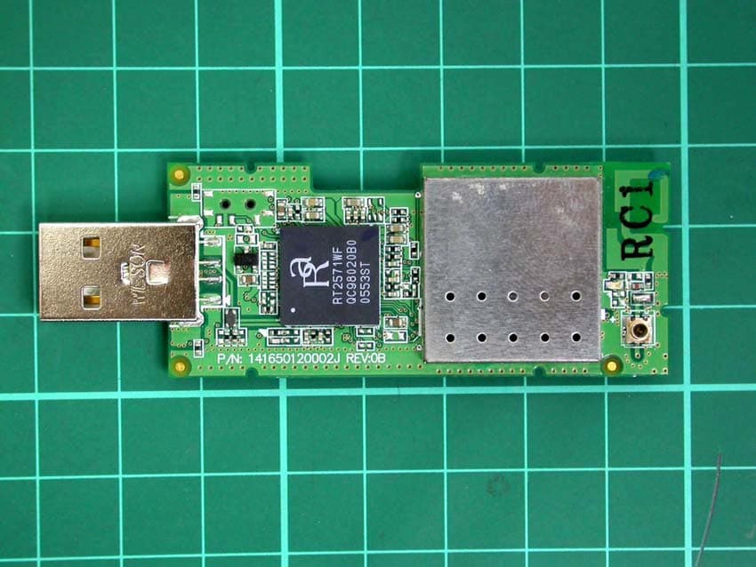
Click to zoom
Application Details
- Equipment Class
- NII - Unlicensed National Information Infrastructure TX
- Date of Grant
- Jul 11, 2006
- Application Purpose
- Original Equipment
- Date of Application
- Jul 10, 2006
- Equipment Note
- 802.11a/b/g Module
- Frequency Range
- 5260.00000000 - 5320.00000000
- Company
- Seiko Epson Corporation
- Country
- Japan
Documents & Files
Document Text
Text extracted from the exhibit documents filed with the FCC. Open a document above to read the original.
Users Manual
1 Operation Guide 2 ContentsMaking a Wireless LAN Connection Quick Connection Mode and Advanced Connection Mode....................5Notes When Using a Wireless LAN...........................................................6 Conditions for Connecting to Compatible Wireless LAN Cards and Access Points ................................................................................................................... 6Supplied Wireless LAN Unit Specifications... ....................................................... 6 Electromagnetic Wave Safe ty Precautions .......................................................... 6 Frequency Precautions ........................................................................................ 6International Travel Precautions .......................................................................... 6Wireless Telegraphy Act Regu lations .................................................................. 7 Notes on Security when Using Wireless LANs .................................................... 7 Connection Limitations..............................................................................8 Supported Resolutions......................................................................................... 8Display Colour...................................................................................................... 8Connection Number ............................................................................................. 8Others .................................................................................................................. 8 Operating the Projector from a Computer via a Network Using the Toolbar .....................................................................................10 Icon Names and Functions ................................................................................ 10Selecting the Projector to Operate ..................................................................... 11Stopping, Pausing, and resuming Projection ..................................................... 11Projecting Only a PowerPoin t Slide Show (Presentation Mode)........................ 12 Switching A/V Mute and Sources............... ........................................................ 12 Projecting Movies from a Computer (Movie Sending) ..........................13Using Multi-Screen Display .....................................................................15 Setting a Virtual Display Arrangement (C omputer Settings) .............................. 15 Operations when Connecting with the Project or ................................................ 16 Multi-Screen Display Preview ............................................................................ 17Example of Adjusting the Virtual Display ........................................................... 18 Setting the EMP NS Connection Environment ......................................19 General settings Tab.......................................................................................... 19Performance Adjustment Tab ............................................................................ 20 Connecting to an Access Point with Wireless LAN Before Connecting ................................................................................... 22Preparing the Computer .......................................................................... 23 Put the Computer into Network Connecti on Status ........................................... 23 Installing the EasyMP Software ......................................................................... 23 Preparing the Projector ........................................................................... 24 Projector Network Settings ................................................................................ 24 Network Settings Function List .............................................................. 25 Basic Menu ........................................................................................................ 25Wireless LAN Menu ........................................................................................... 26Security Menu .................................................................................................... 26Wired LAN Menu ............................................................................................... 28Mail Menu .......................................................................................................... 29SNMP Menu ...................................................................................................... 30Setup Complete Menu ....................................................................................... 30 Connecting in Wireless LAN Advanced Connection Mode.................. 31 Putting the Projector in Co nnection Standby Status .......................................... 31 Starting EMP NS Connection from the Computer ............................................. 31Connecting with the Projector ............................................................................ 33 Disconnecting the Network Connection ................................................ 35When the Projector you want to Connect to is not Displayed ............. 36 Searching by Specif ying the IP Address and Projector Name (For Advanced Connection Mode) ............................................................................................. 36 Registering a Profile for a Projector that is Used Frequently .............. 38 Making a Profile ................................................................................................. 38Searching by Specifying a Profile ...................................................................... 40Managing a Profile............................................................................................. 40 Wireless LAN Security Countermeasures ............................................. 43 Using Encrypted Communicati…
Text truncated - open the document above for the full version.
Users Manual
1 User’s Guide 2 Notations Used in This Guide Attention Indicates procedures which may result in damage or injury if sufficient care is not taken. q Indicates additional information and points which may be useful to know regarding a topic. s Indicates a page where detailed information regarding a topic can be found. g Indicates that an explanation of the underlined word or words in front of this symbol appears in the glossary of terms. See the "Glossary" section of the "Appendices". s p.65 Indicates operating methods and the order of operations. The procedure indicated should be carried out in the order of the numbered steps. [ (Name) ] Indicates the name of the buttons on th e remote control or the control panel. Example: [Esc] button "(Menu Name)" Indicates configuration menu items. Example: "Image" - "Brightness" Procedure 3 Contents Projector Features......................................................................................4 EMP-1715/1705 only............................................................................................ 5 Part Names and Functions ........................................................................6 Front/Top.............................................................................................................. 6Control Panel ....................................................................................................... 7Rear ..................................................................................................................... 8Base ..................................................................................................................... 9Remote Control .................................................................................................. 10 Useful Functions Changing the Projected Image................................................................13 Automatically Detect Incoming Signals and Change the Projected Image (Source Search) ................................................................................................. 13Changing Directly from the Remote Control ...................................................... 14 Functions for Enhancing Projection.......................................................15 Selecting the Projection Quality (Selecting Colour Mode) ................................. 15Hiding the Image and Sound Temporarily (A/V Mute) ....................................... 16Freezing the Image (Freeze).............................................................................. 17Changing the Aspect Ratiog (Resize) ................................................................ 17Pointer Function (Pointer) .................................................................................. 18Enlarging Part of the Image (E-Zoom) ............................................................... 19Using the Remote Control to Operate the Mouse Pointer (Wireless Mouse)..... 20 Adjusting Colour for Several Projectors (Multi-Screen Colour Adjustment)...............................................................................................23 Summary of Adjustment Procedure ................................................................... 23Setting Screen ID ............................................................................................... 23Image Correction Method................................................................................... 24 Security Functions ...................................................................................26 Managing Users (Password Protect) ................................................................. 26Restricting Operation (Operation Lock).............................................................. 29 Configuration Menu Using the Configuration Menu ................................................................31List of Functions.......................................................................................32 Image Menu ....................................................................................................... 32Signal Menu ....................................................................................................... 33Settings Menu .................................................................................................... 34Extended Menu .................................................................................................. 35Network Menu (EMP-1715/1705 Only) .............................................................. 37Info Menu (Display Only).................................................................................... 38Reset Menu........................................................................................................ 39 Troubleshooting Using the Help .......................................................................................... 41Problem Solving....................................................................................... 42 Reading the Indicators....................................................................................... 42When the Indicators Provide No Help................................................................ 45 Appendices Installation Methods ................................................................................ 53Cleaning .................................................................................................... 54 Cleaning the Projector's Surface ....................................................................... 54Cleaning the Lens.............................................................................................. 54Cleaning the Air Filter and Air Intake Vent......................................................... 54 Replacing Consumables ......................................................................... 55 Replacing the Remote Control Batteries ........................................................... 55Replacing the Lamp .......…
Text truncated - open the document above for the full version.
Users Manual
WN6501CEP Wireless LAN 802.11a/b/g USB adapter QIG DRAFT iii COMPLIANCES We: Epson America, Inc. Located at:3840 Kilroy Airport Way MS: 3-13 Long Beach, CA 90806 Tel:562-290-5254 Declare under sole responsibility that the product identified herein, complies with 47CFR Part 2 and 15 of the FCC rules as a Class B digital device. Each product marketed, is identical to the representative unit tested and found to be compliant with the standards. Records maintained continue to reflect the equipment being produced can be expected to be within the variation accepted, due to quantity production and testing on a statistical basis as required by 47CFR 2.909. Operation is subject to the following two conditions: (1) this device may not cause harmful interference, and (2) this device must accept any interference received, including interference that may cause undesired operation. Trade name:Epson Type of Product: Wireless Module for Espon projector Model: WN6501CEP DECLARATION of CONFORMITY According to 47CFR, Part 2 and 15 Class B Personal Computers and Peripherals; and/or CPU Boards and Power Supplies used with Class B Personal Computers COMPLIANCES iv FCC Compliance Statement For United States Users This equipment has been tested and found to comply with the limits for a Class B digital device, pursuant to Part 15 of the FCC Rules. These limits are designed to provide reasonable protection against harmful interference in a residential installation. This equipment generates, uses, and can radiate radio frequency energy and, if not installed and used in accordance with the instructions, may cause harmful interference to radio or television reception. However, there is no guarantee that interference will not occur in a particular installation. If this equipment does cause interference to radio and television reception, which can be determined by turning the equipment off and on, the user is encouraged to try to correct the interference by one or more of the following measures. •Reorient or relocate the receiving antenna. •Increase the separation between the equipment and receiver. •Connect the equipment into an outlet on a circuit different from that to which the receiver is connected. •Consult the dealer or an experienced radio/TV technician for help This device complies with Part 15 of the FCC Rules. Operation is subject to the following two conditions: (1) This device may not cause harmful interference, and (2) this device must accept any interference received, including interference that may cause undesired operation. WARNING The connection of a non-shielded equipment interface cable to this equipment will invalidate the FCC Certification or Declaration of this device and may cause interference levels which exceed the limits established by the FCC for this equipment. It is the responsibility of the user to obtain and use a shielded equipment interface cable with this device. If this equipment has more than one interface connector, do not leave cables connected to unused interfaces. Changes or modifications not expressly approved by the manufacturer could void the user’s authority to operate the equipment. FCC Radiation Exposure Statement: The wireless LAN 802.11a/b/g adapter Model: WN6501CEP complies with FCC radiation exposure limits set forth for an uncontrolled environment. This device should be installed and operated with minimum distance 20 cm between the radiator and your body. The holder of the grant of equipment authorization (Grantee) of the module is responsible for the compliance of the module in its final configuration, provided that the OEM, integrator, and/or end user has complied with all of the instructions provided by the Grantee which indicate installation and/or operating conditions necessary for compliance. COMPLIANCES v The modular transmitter must be labeled with its own FCC ID number, and, if the FCC ID is not visible when the module is installed inside another device, then the outside of the device into which the module is installed must also display a label referring to the enclosed module. This exterior label can use wording such as the following: “Contains Transmitter Module FCC ID: BKMWN6501C” or “Contains FCC ID: BKMWN6501C.” Any similar wording that expresses the same meaning may be used. The Grantee may either provide such a label, an example of which must be included in the application for equipment authorization, or, must provide adequate instructions along with the module which explain this requirement. In the latter case, a copy of these instructions must be included in the application for equipment authorization. DGT WARNING 經型式認證合格之低功率射頻電機,非經許可,公司、商號或使用者均不得擅自變 更頻率、加大功率或變更原設計之特性及功能。 低功率射頻電機之使用不得影響飛航安全及干擾合法通信;經發現有干擾現象時, 應立即停用,並改善至無干擾時方得繼續使用。 前項合法通信,指依電信法規定作業之無線電通信。 低功率射頻電機須忍受合法通信或工業、科學及醫療用電波輻射性電機設備之干 擾。 Article 14 Without permission, any company, firm or user shall not alter the frequency, increase the power, or change the characteristics and functions of the original design of the certified lower power frequency electric machinery. Article 15 The application of lower power frequency electric machineries shall not affect the navigation safety nor interfere a legal communication, if an interference is found, the service will be suspended until improvement is made and the interference no longer exists. The foregoing legal communication refers to the wireless telecommunication operated according to the telecommunications laws and regulations. The lower power frequency electric machinery should be able to tolerate the interference of the electric wave radiation electric machineries and equipments for legal communications or industrial and scientific applications. COMPLIANCES vi 1-1 CHAPTER 1 Wireless LAN 802.11a/b/g USB adapter Introduction Thank you for purchasing the Wireless LAN 802.11a/b/g USB adapter. You are about to install a networking system that is not only fast and powerful, but also easy to set up and simple to maintain. In a short time you and those in …
Text truncated - open the document above for the full version.
Cover Letter(s)
FCC ID: BKMWN6501C Date: Jun. 6, 2006 Modular Approval Request Letter Dear Sir, There’s an Wireless LAN 802.11a/b/g USB adapter that would like to have your authorization as a modular approval. The specific product as below, Wireless LAN 802.11a/b/g USB adapter, with its designed features and specified description, meets special requirements for LMA modular approval on FCC Public Notice DA 00-1407 by cross-reference list below. Company : SEIKO EPSON CORPORATION Model Name : Wireless LAN 802.11a/b/g USB adapter Model Number : WN6501CEP FCC ID : BKMWN6501C Requirement of Public Notice DA00-1407 Reference to WN6501CEP 1. The modular transmitter must have its own RF shielding. The module has its own RF shielding. Please see external photo.pdf 2. The modular transmitter must have buffered modulation/data inputs. The modular has buffered data inputs, it is integrated in chip RT5226. Please see diagram.pdf 3. The modular transmitter must have its own power supply regulation. All power lines derived from the host device are regulated before energizing other circuits internal to the WN6501CEP. Please see circuit.pdf 4. The modular transmitter must comply with the antenna requirements of Section 15.203 and 15.204(c). The WN6501CEP meets the FCC antenna requirements. It has a unique connector. Please see external photo.pdf 5. The modular transmitter must be tested in a stand-alone configuration, i.e., the module must not be inside another device during testing. The WN6501CEP was tested in a stand-alone. Please see conducted set-up photo.pdf and spurious set-up photo.pdf 6. The modular transmitter must be labeled with its own FCC ID number, and, if the FCC ID is not visible when the module is installed inside another device, then the outside of the device into which the module is installed must also display a label referring to the enclosed module. The label position of WN6501CEP is clearly indicated. Please see the label.pdf 7. The modular transmitter must comply with any specific rule or operating requirements applicable to the transmitter and the manufacturer must provide adequate instructions along with the module to explain any such requirements. A copy of these instructions must be included in the application for equipment authorization. The WN6501CEP is compliant with all applicable FCC rules. Detail instructions are given in the Users Manual. Please see Installation guide.pdf 8. The modular transmitter must comply with any applicable RF exposure requirements. For example, FCC Rules in Sections 2.1091, 2.1093 and specific Sections of Part 15, including 15.319(i), 15.407(f), 15.253(f) and 15.255(g), require that Unlicensed PCS, UNII and millimeter wave devices perform routine environmental evaluation for RF Exposure to demonstrate compliance. In addition, spread spectrum transmitters operating under Section 15.247 are required to address RF Exposure compliance in accordance with Section 15.247(b)(4). The WN6501CEP comply with applicable RF exposure requirements. Please see RF safety evaluation. pdf Yours sincerely, Kevin Chen Kevin Chen Intertek Testing Service Taiwan Ltd.
Cover Letter(s)
American Telecommunications Certification Body Inc. 6731 Whittier Ave, McLean, VA 22101 July 4, 2006 RE: Seiko Epson Corporation FCC ID: BKMWN6501C I have a few comments on this Application. Depending on your responses, kindly understand there may be additional comments. 1.) There appears to be some confusion as to the frequencies desired on Form 731. Please review your Application form and correct ant exhibits as necessary. 2.) Is simultaneous transmission possible in both the 802.11b/g and 802.11a bands? If so, then the MPE exhibit should consider the effects of simultaneous transmission. 3.) There appears to be conflicting information as to if this device will be able to transmit outside the permitted frequency bands within North America. Please clarify. 4.) The label is wrong. We need labeling that is applied to this specific product. The label provided claims “Contains Inside”. This is appropriate for the devices which receive a separately approved module – not the module itself. 5.) There is also conflicting information about the modular approval letter. The Manual clearly states that this device will be used in conjunction with Epsom EMP series projectors. Please review. Choose if you want an LMA or full Modular approval. 6.) Please review your Test Report. The band edge emissions test does not appear to conform to the FCC guidance procedures for measurement of DSSS devices. Please review. William H. Graff President and Director of Engineering mailto: [email protected] The items indicated above must be submitted before processing can continue on the above referenced application. Failure to provide the requested information may result in application termination. Correspondence should be considered part of the permanent submission and may be viewed from the Internet after a Grant of Equipment Authorization is issued. Please do not respond to this correspondence using the email reply button. In order for your response to be processed expeditiously, you must submit your documents through the AmericanTCB.com website. Also, please note that partial responses increase processing time and should not be submitted. Any questions about the content of this correspondence should be directed to the sender.
External Photos
Photo 1: External photo of EUT WN6501CEP Photo 2: External photo of EUT
ID Label/Location Info
FCC ID Label Location
Internal Photos
Photo 1: Internal photo of EUT WN6501CEP Photo 2: Internal photo of EUT WN6501CEP Photo 3: Internal photo of EUT WN6501CEP Photo 4: Internal photo of EUT WN6501CEP
RF Exposure Info
FCC ID. : Report No.: EME-010 Page 1 of 7 Maximum Permissible Exposure (MPE) Evaluation Report Report No. : EME-010 Model No. : WN6501CEP Issued Date : Jun. 1, 2006 Applicant : SEIKO EPSON CORPORATION 4897 Shimauchi, Matsumoto-shi, Nagano-ken 390-8640 JAPAN Test By : Intertek Testing Services Taiwan Ltd. No. 11, Lane 275, Ko-Nan 1 Street, Chia-Tung Li, Shiang-Shan District, Hsinchu City, Taiwan This test report consists of 7 pages in total. It may be duplicated completely for legal use with the allowance of the applicant. It shall not be reproduced except in full, without the written approval of Intertek Laboratory. The test result(s) in this report only applies to the tested sample(s). Kevin Chen Project Engineer Reviewed By Jerry Liu FCC ID. : Report No.: EME-010 Page 2 of 7 Table of Contents Summary of Tests ............................................................................................................. 3 1. Introduction .................................................................................................................. 4 2. RF Exposure Limit ....................................................................................................... 5 3. RF Exposure calculations ............................................................................................. 6 4. Test results .................................................................................................................... 6 FCC ID. : Report No.: EME-010 Page 3 of 7 Summary of Tests MPE Evaluation meet FCC OET No. 65: 1997/ IEEE C95.1-1999 Wireless LAN 802.11a/b/g USB adapter -Model: WN6501CEP FCC ID: BKMWN650 Test Reference Results MPE Evaluation FCC Guidelines for Human Exposure IEEE C95.1 Pass FCC ID. : Report No.: EME-010 Page 4 of 7 1. Introduction The EUT operates in the 2.4GHz ISM band. Due to the EUT (include antenna) at its normal operation distance is at least 20 cm from the human body, the EUT was defined as a Mobile Device. The EUT operates in the 2.4GHz ISM band. The EUT (antenna included) is compliant with modular approval and the normal operation distance (after installing in other device, such as router or access point), 20cm from the human body; therefore, the EUT is defined as a Mobile Device. The reason to do the MPE Evaluation is to avoid the RF hazard to human body. The maximum output power and gain of the antenna were used to calculate the limited Power density (S) at 20cm distance away from the product. The limit for Maximum Permissible Exposure (MPE) specified in FCC 1.1310 is followed. According to 1.1307 (b)(1), systems operating under the provisions of this section shall be operated in a manner that ensure that the public is not exposed to radio frequency energy level in excess of the Commission’s guideline. FCC ID. : Report No.: EME-010 Page 5 of 7 2. RF Exposure Limit According to FCC 1.1310: The criteria listed in the following table shall be used to evaluate the environmental impact of human exposure to radio-frequency (RF) radiation as specified in 1.1307(b). Limits for Maximum Permissible Exposure (MPE) Frequency Range (MHz) Electric Field Strength (V/m) Magnetic Field Strength (A/m) Power Density (mW/cm 2 ) Average Time (minutes) (A) Limits for Occupational / Control Exposures 30-300 61.4 0.163 1.0 6 300-1500 - - F/300 6 1500-100,000 - - 5 6 (B) Limits for General Population / Uncontrolled Exposure 30-300 27.5 0.073 0.2 30 300-1500 - - F/1500 30 1500-100,000 - - 1.0 30 F= Frequency in MHz FCC ID. : Report No.: EME-010 Page 6 of 7 3. RF Exposure calculations From FCC 1.1310 table 1, the maximum permissible RF exposure for an uncontrolled environment is 1mW/(cm 2 ) Power density (S) is calculated by the following formula: S = (P * G)/4πR 2 where, S = Power density (mW/cm 2 ) P = Output power to antenna (mW) R = Distance between radiating structure and observation point (cm) G = Gain of antenna in numeric π = 3.1416 Example: Assume a mobile device operates at 2412MHz and its maximum output power is 50mW, and the maximum gain of antenna is 1 (numeric) /0dBi. then the power density (S) = (50 * 1)/4*π*20 2 = 0.00995 (mW/cm 2 ) 4. Test results Test Mode: 802.11b(DSSS Modulation) operating mode Channel Channel Frequency (MHz) Maximum antenna gain (numeric) Output power to antenna (mW) Power density (mW/cm 2 ) Limit of power density (mW/cm 2 ) 1 (lowest) 2412 1.96 88.10 0.03433 1.0 6 (middle) 2437 1.96 69.34 0.02702 1.0 11 (highest) 2462 1.96 78.89 0.03074 1.0 Test Mode: 802.11g(OFDM Modulation) operating mode Channel Channel Frequency (MHz) Maximum antenna gain (numeric) Output power to antenna (mW) Power density (mW/cm 2 ) Limit of power density (mW/cm 2 ) 1 (lowest) 2412 1.96 139.64 0.05542 1.0 6 (middle) 2437 1.96 112.46 0.04383 1.0 11 (highest) 2462 1.96 123.59 0.04816 1.0 FCC ID. : Report No.: EME-010 Page 7 of 7 Test Mode: 802.11a(OFDM Modulation) operating mode Channel Channel Frequency (MHz) Maximum antenna gain (numeric) Output power to antenna (mW) Power density (mW/cm 2 ) Limit of power density (mW/cm 2 ) 36 5180 1.87 42.76 0.01588 1.0 40 5200 1.87 36.98 0.01373 1.0 48 5240 1.87 33.73 0.01252 1.0 Test Mode: 802.11a(OFDM Modulation) operating mode Channel Channel Frequency (MHz) Maximum antenna gain (numeric) Output power to antenna (mW) Power density (mW/cm 2 ) Limit of power density (mW/cm 2 ) 52 5260 1.87 33.19 0.01232 1.0 60 5300 1.87 31.70 0.01177 1.0 64 5320 1.87 29.31 0.01088 1.0 The Notice in Installation Manual has been stated as below: While installing and operating this transmitter, the radio frequency exposure limit of 1mW/(cm*cm) may be exceeded at distances close to the transmitter. therefore, the user must maintain a minimum distance of 20 cm from the device at all time.
Test Report
FCC ID. : BKMWN6501C Report No.: EME-060590 Page 1 of 94 EMC TEST REPORT Report No. : EME-060590 Model No. : WN6501CEP Issued Date : Jun. 1, 2006 Applicant : SEIKO EPSON CORPORATION 4897 Shimauchi, Matsumoto-shi, Nagano-ken 390-8640 JAPAN Test By : Intertek Testing Services Taiwan Ltd. No. 11, Lane 275, Ko-Nan 1 Street, Chia-Tung Li, Shiang-Shan District, Hsinchu City, Taiwan This test report consists of 94 pages in total. It may be duplicated completely for legal use with the allowance of the applicant. It shall not be reproduced except in full, without the written approval of Intertek Laboratory. The test result(s) in this report only …
Text truncated - open the document above for the full version.
Contact Information
Applicant
Yoshinobu Murakami(CS/Quality Assurance Department)
Technical Contact
Intertek Testing Services Taiwan LtdJerry Liu
[email protected]+886 3 519 1411
11, Lane 275, Ko Nan 1st Street · Hsinchu · Taiwan
Test Firm
Intertek Testing Services Taiwan Ltd.Alpha Liu
Technical Specifications
| # | Rule Parts | Frequency Range | Power Output |
|---|---|---|---|
| 2 | 15E | 5.26 GHz - 5.32 GHz | 33.00 mW |
Other Applications from Seiko Epson Corporation
BKMAE-N37663U02
Jul 17, 2024WLAN BT Module
Equipment Class
NII - Unlicensed National Information Infrastructure TX
BKMAE-DTP9757
Mar 04, 2023Streaming Media Player
Equipment Class
DSS - Part 15 Spread Spectrum Transmitter
BKMAE-WH55B
Jul 18, 2022REMOTE CONTROLLER
Equipment Class
DTS - Digital Transmission System
BKMAE-WH5674B
Jul 17, 2022REMOTE CONTROLLER
Equipment Class
DTS - Digital Transmission System
BKMFBM381A
Jul 10, 2022Printer
Equipment Class
NII - Unlicensed National Information Infrastructure TX