BMW-52614TX27JLX MicroDrive Radio Control
TOMY International, Inc.
Click to zoom
Application Details
- Equipment Class
- DXX - Part 15 Low Power Communication Device Transmitter
- Date of Grant
- Nov 14, 2011
- Application Purpose
- Original Equipment
- Date of Application
- Nov 14, 2011
- Equipment Note
- JLX MicroDrive Radio Control
- Frequency Range
- 27.14500000 - 27.14500000
- Company
- TOMY International, Inc.
- Country
- United States
Documents & Files
Document Text
Text extracted from the exhibit documents filed with the FCC. Open a document above to read the original.
Users Manual
Move joystick(s) as indicated by solid arrows. Vehicle will move in direction as indicated by outlined arrow. SIMPLE SKILL LEVEL: MODERATE SKILL LEVEL: EXPERT SKILL LEVEL: MAXIMUM RAMP HEIGHT 24” 18” MAXIMUM RAMP HEIGHT 5” MAXIMUM RAMP HEIGHT 24” DIRECTION CONTROLS PROPER OPERATION AND STORAGE OF YOUR VEHICLE TRICKS AND STUNTS (for outdoors only) BATTERY REQUIREMENTS / INSTALLATION FOR VEHICLE JLX MICRODRIVE™ ACTION FEATURES 2-SIDED BODY DESIGN HIDDEN INTERNAL ANTENNA FOR LONG RANGE ACTION RUBBER TIRES FOR MASSIVE SUPER BOUNCE ACTION! SUPER-GRIP TIRE TREAD FOR BETTER OFF- ROAD TRACTION DUAL AWD MEGA-TORQUE ACTION BATTERY REQUIREMENTS / INSTALLATION FOR TRANSMITTER 1. Remove battery cover as shown and install (2) AAA / LR03 1.5 Volt batteries. Replace cover. Move power button “ON” and the red LED light will come on. This will show you that the battery is good and the transmitter is ready for operation. PLEASE NOTE: Vehicle power switch must be in the “ON” position to receive commands from the transmitter. 2. Change batteries when LED is dim or not on. SAFETY PRECAUTIONS (Keep manual for future reference) This vehicle is not recommended for children under the age of 6 years. Please read all of the instructions before operating this vehicle. Always follow general safety rules while operating vehicle: avoid hitting pets, furniture or people. Do not pick up vehicle while it is in motion, keep hands, hair and clothing away from this vehicle when the power switch is turned to the “ON” position. Remove batteries when vehicle is stored. Avoid tire contact on painted or varnished surfaces. The JLX MICRODRIVE™ is built with an automatic shut-off function if the vehicle reaches excessive temperature during operation. If the vehicle stops after prolonged period of operation, turn off vehicle and controller, remove batteries from vehicle and cease operation for ten (10) minutes. Reinsert batteries and resume play. ® CONFORMS TO THE SAFETY REQUIREMENTS OF ASTM F963. Part of the “R”US Family of Brands. Customer Infomation: Color and contents may very from item shown. Where applicable, remove all packing before giving this item to your child. FAST LANE is a mark of Geoffrey, LLC, a subsidiary of Toys“R”Us, Inc. © 2011 Geoffrey, LLC Made in China Distributed in the United States by Toys“R”Us, Inc., Wayne, NJ 07470 Distributed in Australia by Toys“R”Us (Australia) PTY Ltd. Regents Park NSW 2143 www.toysrus.com Do not mix old and new batteries. Do not mix alkaline, standard (carbon zinc), or rechargeable (nickel-cadmium) batteries. NOT INCLUDED 5. Avoid operating around CB radios, high voltage electrical wires and large steel-reinforced concrete buildings. 6. Avoid running your vehicle and another vehicle on the same frequency. 7. DO NOT use in salt water. 8. Vehicle and transmitter are not waterproof. Do not immerse or use in water. 1. Best operation of vehicle is on a textured paved surface. 2. Always operate your vehicle within a range of 50 feet from you. 3. Always operate your vehicle on dry surfaces away from cars and other full-size vehicles. 4. Always store your vehicle in a cool, dry place and off of painted or varnished surfaces. Here are a few of the exciting tricks and stunts you can do. The following tricks and stunts take practice and skill. Attempt simple skill level tricks before going on to more advanced tricks. Remember you will need to practice to achieve these stunts. FCC NOTE: This equipment has been tested and found to comply with the limits for a Class B digital device, pursuant to Part 15 of the FCC Rules. These limits are designed to provide reasonable protection against harmful interference in a residential installation. This equipment generates, uses and can radiate radio frequency energy and, if not installed and used in accordance with the instructions, may cause harmful interference to radio communications. However, there is no guarantee that interference will not occur in a particular installation. If this equipment does cause harmful interference to radio or television reception, which can be determined by turning the equipment off and on, the user is encouraged to try to correct the interference by one or more of the following measures: • Reorient or relocate the receiving antenna. • Increase the separation between the equipment and receiver. • Connect the equipment into an outlet on a circuit different from that to which the receiver is connected. • Consult the dealer or an experienced radio/TV technician for help. U.S. FCC Warning: Changes or modifications to this unit not expressly approved by the party respon-sible for compliance could void the user’s authority to operate the equipment. This device complies with Part 15 of the FCC Rules. Operation is subject to the following two conditions: (1) this device may not cause harmful interference, and (2) this device must accept any interference received, including interference that may cause undesired operation. This Class B digital apparatus complies with Canadian ICES-003. Cet appareil numérique de la classe B est conforme à la norme NMB-003 du Canada. “Operation is subject to the following two conditions: (1) this device may not cause interference, and (2) this device must accept any interference, including interference that may cause undesired operation of the device.” Carrier frequency and field strength Frequency Channel: 27.145 MHz 27.145 MHz Field Strength: 68.7 dBμv/m @ 3m. WHEELIE FLIP 6. While running the car with the drive wheels in front, quickly reverse both control buttons. This should cause the car to flip. (To identify drive wheels, hold car off of ground. Move control button and drive wheels will spin.) REVERSE RAMP FLIP 4. Build a semi-circular ramp 24 inches high and run the car through it. BARREL ROLL 5. While driving the car straight at full speed, make a sudden turn causing the car to roll. Too sharp of a turn will cause the car to spin instead of roll. 1. On the vehicle bottom, using a Phillps screwdri…
Text truncated - open the document above for the full version.
External Photos
General Appearance of the EUT
Operational Description
Operational Description The Equipment Under Test(EUT) is a transmitter for toy operating at 27.145MHz, which is controlled by a RF Remote Control, and powered by 2*1.5V ”AA” batteries. There are four switches: forward, backward, turn left and turn right. The brief circuit description is listed as follows: Description Function Component Antenna Transmit modulated RF signal Ant LPF Filter Suppression of spurious emissions C2, C1, T1, L1 RF Power Amplifier and Modulator Modulate the carrier and amplify the modulated RF sighal Q2 Oscillator Generate 27.145MHz carrier Y1, Q1 Encode IC Generate code signal molulator U2
Test Report
DONGGUAN EMTEK CO., LTD. REPORT NO:ED111031151E FCC ID: BMW-52614TX27 DATE: 11/08/2011 Page 1 of 16 ELECTROMAGNETIC EMISSIONS COMPLIANCE REPORT INTENTIONAL RADIATOR CERTIFICATION TO FCC PART 15 SUBPART C REQUIREMENT OF JLX MicroDrive Radio Control (Transmitter) MODEL No.: 52614/52614MP Trademark: N/A FCC ID: BMW-52614TX27 REPORT NO: ED111031151E ISSUE DATE: November 08, 2011 Prepared for Learing Curve Brands. Inc. 1111 W. 22nd Street Suite 320 Oak Brook, IL 60523 United States Prepared by DONGGUAN EMTEK CO., LTD. No.281,Guantai Road,Nancheng District, Dongguan, Guangdong, China TEL: 86-769-22807078 FAX: 86-769-22807079 DONGGUAN EMTEK CO., LTD. REPORT NO:ED111031151E FCC ID: BMW-52614TX27 DATE: 11/08/2011 Page 2 of 16 VERIFICATION OF COMPLIANCE Applicant: Learing Curve Brands. Inc. 1111 W. 22nd Street Suite 320 Oak Brook, IL 60523 United States Manufacturer: Asahi Dynamic Industries Co., Ltd. Supplier: Jozen International Co., Ltd. Product Description: JLX MicroDrive Radio Control Trademark: N/A Model Number: 52614/52614MP FCC ID Number: BMW-52614TX27 Serial Number: N/A File Number: ED111031151E Date of Test: October 31, 2011 to November 07, 2011 We hereby certify that: The above equipment was tested by Dongguan EMTEK Co., Ltd. The test data, data evaluation, test procedures, and equipment configurations shown in this report were made in accordance with the procedures given in ANSI C63.4 (2009) and the energy emitted by the sample EUT tested as described in this report is in compliance with conducted and radiated emission limits of FCC Rules Part 15.227. The test results of this report relate only to the tested sample identified in this report. Approved By Sam Lv / Q.A. Manager DONGGUAN EMTEK CO., LTD. DONGGUAN EMTEK CO., LTD. REPORT NO:ED111031151E FCC ID: BMW-52614TX27 DATE: 11/08/2011 Page 3 of 16 Ta b l e o f C o n t e n t s 1. GENERAL INFORMATION ................................................................................................. 4 1.1 Product Description................................................................................................................................. 4 1.2 Related Submittal(s) / Grant (s)............................................................................................................... 4 1.3 Test Methodology ................................................................................................................................... 4 1.4 Special Accessories ................................................................................................................................. 4 1.5 Equipment Modifications ........................................................................................................................ 4 1.6 Test Facility............................................................................................................................................. 5 2. System Test Configuration......................................................................................................6 2.1 EUT Configuration.................................................................................................................................. 6 2.2 EUT Exercise .......................................................................................................................................... 6 2.3 Test Procedure......................................................................................................................................... 6 2.4 Limitation ................................................................................................................................................ 6 2.5 Configuration of Tested System.............................................................................................................. 8 3. Summary Of Test Results........................................................................................................9 4. Description of test modes......................................................................................................... 9 5. Conducted Emissions Test (Not applicable in this report).............................................. 10 5.1 Measurement Procedure:....................................................................................................................... 10 5.2 Test SET-UP (Block Diagram of Configuration).................................................................................. 10 5.3 Measurement Equipment Used: ............................................................................................................ 10 5.4 Measurement Results: ........................................................................................................................... 10 5.5 Conducted Measurement Photos:.......................................................................................................... 10 6. Radiated Emission Test .........................................................................................................11 6.1 Measurement Procedure ........................................................................................................................ 11 6.2 Test SET-UP (Block Diagram of Configuration).................................................................................. 11 6.3 Measurement Equipment Used: ............................................................................................................ 12 6.4 Measurement Results ............................................................................................................................ 12 6.5 Radiated Measurement Photos: ............................................................................................................. 14 7. Occupied Bandwidth..............................................................................................................15 7.1 Measurement Procedure ...........................................................…
Text truncated - open the document above for the full version.
Test Setup Photos
Setup Photos
Contact Information
Applicant
Paul Mello Jr(Product Integrity Manager)
Technical Contact
TeleconformityMark Koop
[email protected]+31 84 8395876
Rietven 31 · Enschede, Overyssel · Netherlands
Test Firm
EMTEK (DONGGUAN) CO.,LTDSam Lv
Technical Specifications
| # | Rule Parts | Frequency Range | Power Output |
|---|---|---|---|
| 1 | 15C | 27.145 MHz - 27.145 MHz | - |
Other Applications from TOMY International, Inc.
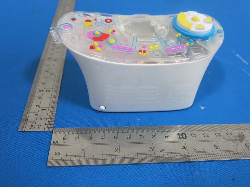
BMW-L61112
Mar 17, 2015The Console
Equipment Class
DXX - Part 15 Low Power Communication Device Transmitter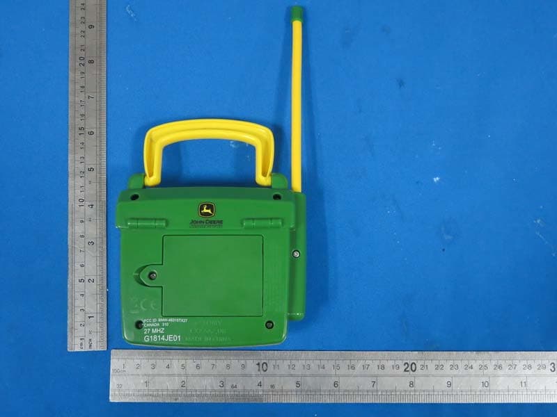
BMW-46315TX27
Aug 11, 2014JD RC Fix- It Up Johnny
Equipment Class
DXX - Part 15 Low Power Communication Device Transmitter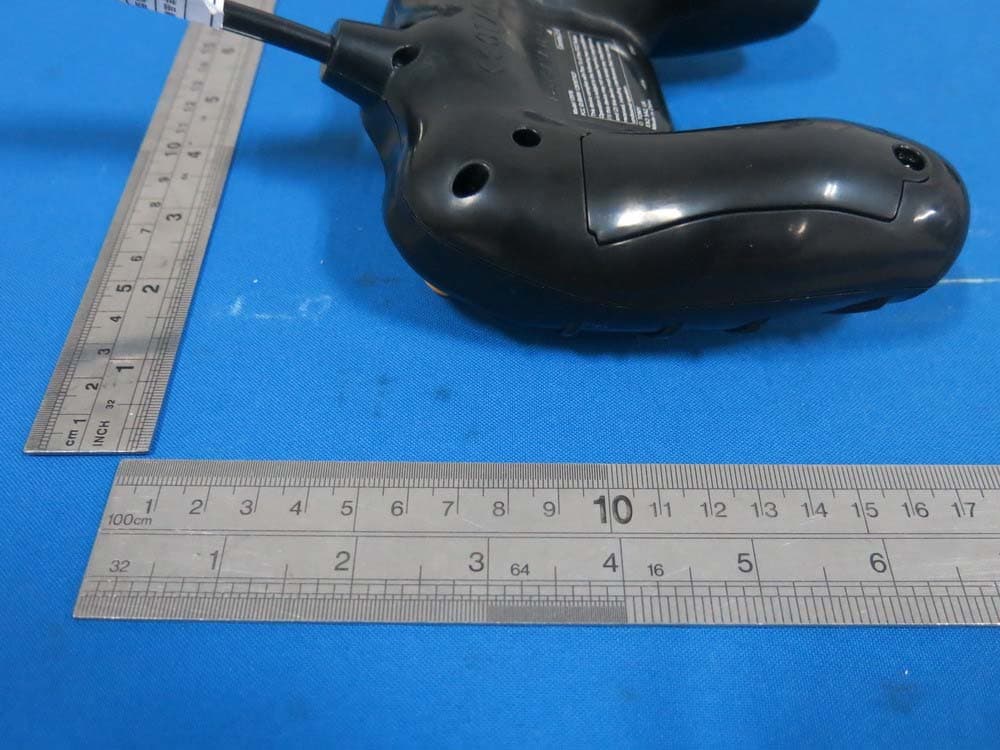
BMW-12978TX27
Jan 14, 2014MT truck
Equipment Class
DXX - Part 15 Low Power Communication Device Transmitter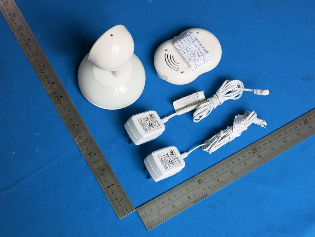
BMWTFY7648C
Jul 28, 2013Talk and Soothe Vid Monitor
Equipment Class
DSS - Part 15 Spread Spectrum Transmitter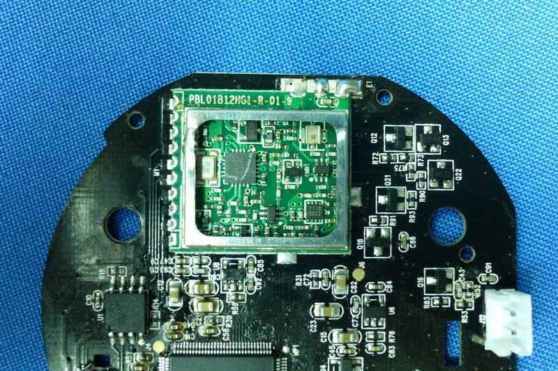
BMWTFY7648P
Jul 25, 2013Talk and Soothe Video Monitor
Equipment Class
DSS - Part 15 Spread Spectrum Transmitter