BSFFC-N21SComputer FC-NOTE Series
NEC Corporation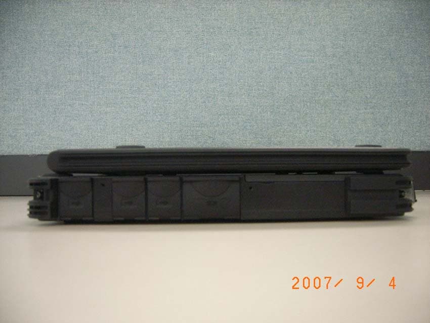
Click to zoom
Application Details
- Equipment Class
- NII - Unlicensed National Information Infrastructure TX
- Date of Grant
- Nov 08, 2007
- Application Purpose
- Original Equipment
- Date of Application
- Nov 07, 2007
- Equipment Note
- Computer FC-NOTE Series
- Frequency Range
- 5745.00000000 - 5805.00000000
- Company
- NEC Corporation
- Country
- Japan
Documents & Files
Document Text
Text extracted from the exhibit documents filed with the FCC. Open a document above to read the original.
Users Manual
NEC Factory Computer FC-NOTE Series User’s Manual FC-N21S Notes on Use The following includes information necessary for proper and safe operation of the product. Before using this product, read this manual carefully and keep cautions. Keep this manual at hand to see whenever it is necessary. The following symbols are used in this manual so that the user can avoid personal injury or damage to the properties. The meaning of these symbols are as shown below. Fully understand the meaning before reading this manual. Indicates there is a risk of death or serious personal injury. Indicates there is a risk of personal injury or property damage. WARNING CAUTION Prohibited Indicates prohibited action. Attention to fire Indicates there is a risk of fume and/or a fire. Attention to electric shock Indicates there is a risk of electric shock. Attention to personal injury Indicates there is a risk of personal injury. Attention to laser beam Indicates there is a risk of loss of eyesight due to laser beam. Attention to high temperature Indicates there is a risk of failure due to high temperature. Unplug the power cord. Indicates an instruction to unplug the power cord. Connect grounding conductor. Indicates an instruction to connect the grounding conductor. The following symbols are used to avoid personal injury or property damage due to an improper operation. RN General If smoke, odor, noise, or abnormal heat is generated, immediately turn off the power of this product and disconnect the power plug from the outlet. Remove a battery, if installed, after making sure that you can safely remove it. Using the computer in such conditions may cause a fire, burn, and/or electric shock. Do not hold the power plug with a wet hand. Do not hold the plug while your hands are wet. Failure to follow this warning may cause an electric shock. Do not touch the computer when it thunders. Do not touch the computer, connected cables, and peripheral devices, or install/remove such devices when a thunderstorm is approaching. Failure to follow this warning may cause an electric shock due to thunderbolt. Do not disassemble or modify the product. Failure to follow this warning may cause an electric shock, fumes, and/or fire. Do not place the product in a fire, apply excess heat, or short-circuit the terminal. Failure to follow this warning may cause a heating, fire, and/or explosion. WAING Installation Environment Observe the following precautions and use the product in a place where environmental requirements are satisfied. Failure to follow this warning may cause an electric shock, fumes, and/or fire. − Do not install or use the product in a location with medical vapor emitting in the air or medicals being contact with the product. − − − Do not use the product into which any liquid such as water, metals, and other foreign substances are entered. Do not use or store the product in a place of extremely high or low temperature or drastic temperature change. The AC cord shipped with this product can be exclusively used for 100 VAC. Do not connect this AC cord to an outlet of which rating exceeds 125 VAC. The AC adapter and AC cord are designed on the assumption that it is connected to this product. Do not use them for any other equipment. WARNING − Power Supply and Power Cord The AC adapter and AC cord are designed on the assumption that it is connected to this product. The AC adapter may be damaged if it is connected to a device other than this product. The AC cord must be approved by an acceptable accredited agency responsible for evaluation in the country where the AC cord will be installed. The AC cord shipped with this product can be exclusively used for the specified country. Do not connect the power cord to an outlet that has an illegal number of connections. The electric current exceeding the rated flow overheats the outlet, which may cause a fire. The AC cord shipped with this product can be exclusively used for 100 VAC. Do not connect this AC cord to an outlet of which rating exceeds 125 VAC. Failure to follow this instruction may cause a fire and/or electric shock. Insert the power plug into the outlet as far as it goes. A halfway inserted power plug may cause a fire and/or an electric shock. Do not use this product if dusts are accumulated on the AC power cord plug. With dust accumulated power plug, the electrical discharge (tracking) occurs between plug pins and it may cause a fire. Always hold the plugs of the AC cord in its removal. Do not pull the cord. Breaking of wire may cause a fire. Do not use the AC cord with the plug blades being unstable. Poor connection may cause a fire. Do not pull the AC cord forcibly or put any heavy object on it. Breaking of wire may cause a fire and/or electric shock. 修正 WARNING WARNING Power Supply and Power Cord The drip-proof and dust-proof performance conforming to IP54 are not applied to the AC adapter and AC cord. Follow instructions described below when handling them to prevent fume, fire, and/or electric shock to occur. − − − − − − − − − − − Do not drop or give impact to the AC adapter. Do not use the power cord with bent or bundled state. Do not forcedly bend the root of the power cord. Do not put any heavy object on the AC adapter and power cord. Do not wrap the AC adapter with cloth or the like. Do not use the AC adapter in a place where the liquid such as water splashes Do not use any damaged AC cord and/or AC adapter. Do not put the AC adapter in a place near the thermal appliance. Do not put the AC adapter in a place where temperature changes drastically (e.g., near the exhaust port of air conditioner and vicinity of entrance). − Do not use the AC adapter in an area where inflammable gas and/or combustible substance are placed. Do not put the AC adapter in a place where lamp black and/or steam is generated (e.g., galley and near the humidifier). Do not use the AC adapter in a place where salinity (e.g., sea breeze) or the corrosi…
Text truncated - open the document above for the full version.
Users Manual
3.4.2 Charging Battery WARNING Risk of explosion if battery is replaced by incorrect type. Dispose of used batteries according to the instructions The battery is not charged any more if its temperature exceeds 60ºC. In battery charging status, remove the AC adapter only after the battery is fully charged. It the AC adapter is removed on the way, the battery cannot be charged fully. To charge the battery, first connect the AC adapter to FC-N21S and a power outlet. The battery charge LED on FC-N21S illuminates in orange to indicate that the battery is now being charged. It is recommended to turn off the power of FC-N21S while the battery is charged. After the battery is fully charged, the battery charge LED goes off. It takes about three hours to charge the battery fully. Just after the battery is fully charged, do not take the procedure of removing the AC adapter from FC-N21S and reconnecting it to start charging again. Failure to follow this instruction may cause the battery to be damaged. If an error occurs in the battery, the battery charge LED blinks. The temperature may rise extraordinary or the battery may be defected. Move FC-N21S to a place of good ventilation or stop using FC-N21S to lower its temperature. If the battery charge LED blinks still, remove the AC adapter from FC-N21S and stop using it. Contact your service representative. 3.4.3 Initializing Battery Initializing the battery is intended to recover its performance decreased temporarily. The initialization process consists of full charge, full discharge and full recharge of the battery in the order. It takes about 4.5 hours for the initialization. Initialize the battery in the following cases: FC-N21S can be operated by the battery for a shorter period than before. Repeating battery charging in other than the full discharge state may cause the full-chargeable level of the battery to be reduced, which then may shorten the driving period. This is called battery’s memory effect. Because the battery is just purchased or has not been used for a long period, its performance is reduced temporarily. The indicator of the remaining battery level shows some error. 1. Turn off the power of FC-N21S if operated. 2. If the batter pack is not installed, install the battery pack in FC-N21S. 3. If the AC adapter is not connected to FC-N21S yet, connect the AC adapter to FC-N21S and the power cord to an AC outlet. 4. If the battery charge lamp blinks, remove the battery pack from FC-N21S once and install it again. 5. Charge the battery fully (until the battery charge lamp disappears). 6. Turn on the power of FC-N21S. If the NEC logo screen appears, press F2 to display the BIOS Setup Menu. 7. Unplug the power cord from the AC outlet and remove the AC adapter from FC-N21S. 8. Select [Battery refresh] in the Power Management menu and press Enter. 9. If message "Refresh your battery now?" select [Yes] and press Enter. The following dialog box appears. Refresh battery program Press Y to start refresh, N to exit <ESC> to shutdown system 10. Press Y to start battery initialization. Whilthb tti i iti lid lthLCDdilld 3.4.4 Checking Remaining Battery Level To activate the screen, wait for several minutes before the AC adapter is disconnected from FC-N21S. "Total time remaining" may be different from the actual operation time depending on the operation status of FC-N21S. For Windows XP 1. Click [Start] → [Control Panel] → [Performance and Maintenance] → [Power Options]. Then the [Power Options Properties] dialog box appears. 2. Select the [Power Meter] tab and check [Show details for each battery.]. For Windows XP, the dialog box shown below appears to allow you to check the remaining battery level. 3.4.5 Replacing Battery If a battery of an invalid type is substituted for the old one, it may explode. Always use a spare battery of an option. For used batteries, see "3.4.6 Recycling Batteries". Do not disassemble batteries. Batteries are consumables. Repeating charging and discharging a battery causes its charging ability to decrease. If the full discharging time becomes shorter, initialize the battery. If the time cannot be recovered still, replace the battery with a spare. To replace the battery, follow the procedure below: 1. Leave FC-N21S in the power-off state and uplug the AC adapter. 2. Turn FC-N21S upside down. 3. Remove the screws (4) fixing the battery cover and remove the battery cover. Battery cover 4. Pull up the battery removal support perpendicularly and lift the battery from the battery storage area. 5. Insert a new battery into the battery storage area from the top perpendicularly to make the connectors contact with each other. WARNING Risk of explosion if battery is replaced by incorrect type. Dispose of used batteries according to the instructions Install the battery with the battery removal support pulled out. 6. Put the battery cover on the original position and drive the screws (4) to fix the cover. Put the cover so that the battery removal support may not be pinched. If dust and/or dirt adhere to the silicon rubber on rear of the cover, the water-proof and/and dust-proof performance of the cover may be reduced. Wipe the silicon rubber to remove dust and dirt before installing 3.4.6 Recycling Batteries A lithium ion battery is used for FC-N21S. Lithium ion batteries are valuable resources being recyclable. To protect valuable resources, do not dispose batteries becoming unnecessary but bring them to any of the following carry-on centers: * For details of the carry-on centers, see the NEC environmental web page below: URL:http://www.nec.co.jp/eco/ja/products/3r/indes_denchi.html Notes on handling batteries in recycling Insulate connectors with tape. Do not peel off coating. Do not disassemble batteries. To keep batteries, enter them in a rugged case and put the lid on the case. Keep batteries so that they may not get wet with rain. Do not leave batteries in the sun. 3.4.7 Actions Tak…
Text truncated - open the document above for the full version.
Users Manual
(This page is intentionally left blank.) Chapter 5 Installing OS and Applications 5.1 WINDOWS XP PRE-INSTALLED MODEL 5.1.1 Configuration of Windows XP Pre-installed Model FC-N21S of Windows XP pre-installed model has Microsoft Windows XP Professional installed at factory shipment to be automatically booted at power-on. The parameters are previously set to the factory defaults as shown in the table below. Accordingly, you may not enter them on booting of FC-N21S. Parameter Factory default Owner FC-USER Organization (Not set) Computer name FCN21S-XXXXX Value "XXXXX" in the computer name shows the lowest five digits of the product ID of Microsoft Windows XP Professional. For the product ID, see the Microsoft Windows XP Professional license label pasted on the bottom of FC-N21S. For how to change the computer name, see "Specify computer and workgroup names" in the Online Help of Microsoft Windows XP Professional. To change the owner or organization, see next subsection "5.1.1.1 Changing Owner and/or Organization by Modifying Registry" or provide re-setup for Windows XP. For the re-setup, see "l5.1.2 Re-setup of Windows XP in FC-N21S of Pre-installed Model". For the HDD installed in FC-N21S of pre-installed model, the first and second partitions (or system and remaining areas respectively) are formatted at shipment from factory. To change the format so as to assign the second partition (remaining area) to more than one drive, select [Start] → [Control Panel] → [Performance and Maintenance] → [Administrative Tools] → [Computer Management] → [Disk Management] after the setup is completed. Capacity (1st HDD) First partition Second partition 20GB (NTFS) Standard HDD: About 40GB (NTFS) Wide temperature range HDD: About 20GB (NTFS) Note that Windows XP installed in FC-N21S is not specified as an upgrading/downgrading product by Microsoft. 5.1.1.1 Changing Owner and/or Organization by Modifying Registry The registry has a variety of information required to operate Windows XP. Changing the registry incorrectly may cause Windows XP to be started improperly. Change the registry with sufficient care. If Windows XP is not started or started improperly after change of the registry, reinstall Windows XP. Be sure to change the registry before installing applications in FC-N21S. If the registry is changed after some applications are installed, the changed registry may not be reflected on the versions of the applications. However, Windows XP can operate normally. Only symptoms such as shown by an example below may appear: Ex: When organization and/or owner are changed after Microsoft Excel is installed, Selecting [Control Panel] → [Organization/owner in System] causes the organization and owner after registry change to be displayed. The version information in the Help file of Excel indicates the organization and owner after registry change. (1) Registry change procedure 1. Start WindowsXP. 2. Click [Start] → [Run...], type "c:\windows\regedit.exe", and click [OK]. 3. Open HKEY_LOCAL_MACHINE\SOFTWARE\Microsoft\Windows NT\CurrentVersion. 4. Click the following items and change the organization and/or owner. Registered Organization Registered Owner 5. Click [File] → [Exit] to exit the registry editor. (2) Organization/owner check procedure 1. Start Windows XP. 2. Right-click [My Computer] and click [Property]. (3) Microsoft Windows XP Professional License Label (COA label) FC-N21S of pre-installed mode has Last Known Good Configuration Microsoft Windows XP Professional license label (COA label) pasted on the bottom of FC-N21S. The label includes some important information including "Product ID". Take sufficient care on that label so that the label may not be damaged, broken or peeled off. The Microsoft Windows XP Professional license label (COA label) shall not be re-issued if it is damaged, broken or peeled off. Note: Because the COA label is partially transparent and not laminated, it seems to get a hole or be broken. However, it does not indicate that the label is damaged. The transparent part of the label may have a unique shape due to special processing to be different from others. 5.1.2 Re-setup of Windows XP in FC-N21S of Pre-installed Model 5.1.2.1 − − − − − − − − Re-setup Re-setup can recover the damaged system of FC-N21S to the normal state. However, files stored in the HDD are erased. In addition, it takes much time for re-setup. Check if re-setup is absolutely required before starting the job. (1) Situations requiring re-setup Provide re-setup for the system in FC-N21S in the following situations: 1. Recovering system from trouble At power-on, the power lamp goes on but Windows does not start. One or more programs in the HDD do not operate. System files in the HDD are erased unintentionally. Repairing the system cannot solve problem. Started Windows XP in the safe mode, but problem cannot be solved. 2. Changing settings of Windows The settings of Windows are required to be recovered to the factory defaults. 3. Changing the settings of the HDD The capacity of drive C is required to be changed. The HDD is required to be configured with only a single partition. The re-setup is to return the system in FC-N21S to that in the same state at shipment from factory based on the data stored in the recovery CD-ROMs if the system is damaged. The re-setup is also required after the configuration of the HDD is changed. It is because formatting (initializing) the HDD causes the system to be erased. (2) System repair procedure The system can be repaired in either of the following two ways. The proper way is dependent on the system status. Try the simpler method first in the order shown below: 1. Repair the system by using the [Last Known Good Configuration] menu. 2. Provide the system with re-setup by using the recovery CD-ROMs. Notes on re-setup Make a backup of data. Some re-setup methods may erase all or a part of data you have created. For the re-setup methods, see "5.1.2.2 Standard and Custom Re-setups". …
Text truncated - open the document above for the full version.
Cover Letter(s)
November 7, 2007 ATCB ID: ATCB005578 FCC ID: BSFFC-N21S Attention: Mr. Doug Noble Dear Mr. Doug Noble Please find the following our reply to your comments; 1. We have uploaded the revised Internal Photos on the server. 2. We understood these documents are treated as you indicated. Also, please find the technical documents for notebook as we have uploaded on the server. 3. This was just error writing. I have uploaded the revised SAR Test Repot. 4. Regarding 15C test report, "11a Data Rate and Antenna Check" of Page 34 of 15C test report is the reference data in order to make a decision the worst case. The frequency between 5180 to 5320MHz is treated as one band, so we filled 33.57mW at 5320MHz by stating on Page 28 of 15E test report into Form 731. 33.57mW (15.26dBm) which is the highest value among 5180 - 5320MHz and 47.42mW (16.76dBm) which is the highest one among 5745 - 5805MHz are adopted. "Reference data ANT: Main (Worst), 5260MHz" is also reference data to make a decision the worst case as well as 15C test report. Also as there is difference of measument method of 15C and 15E, it resulted in differences of power. 15C: Peak Value<---The Maximum Peak Output Power was measured with a power meter (tested bandwidth: 50MHz) connected to the antennaport. 15E: Sample Value <---The test was made with the spectrum analyzer that has a function of channel-power measurement. We followed the method 1 specified in DA-02-2138A1. 5. We will send the revised user manual as soon as possible. Thank you very much for your prompt attention. Best regards, Kanako Sanda (Ms.) Application Section Head Services Div. TEL +81-596-24-8116 FAX +81-596-24-8124 E-mail: [email protected]
External Photos
NEC Corporation Factory Computer FC-NOTE series FCC ID: BSFFC-N21S Model: FC-N21S/BY5SS External Photo Front Rear NEC Corporation Factory Computer FC-NOTE series FCC ID: BSFFC-N21S Model: FC-N21S/BY5SS Top Right NEC Corporation Factory Computer FC-NOTE series FCC ID: BSFFC-N21S Model: FC-N21S/BY5SS Left Open view
Internal Photos
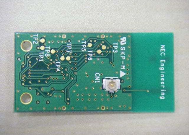
NEC Corporation Factory Computer FC-NOTE series FCC ID: BSFFC-N21S Model: FC-N21S/BY5SS Internal Photo Internal view Touch Panel Connection Board (Front) NEC Corporation Factory Computer FC-NOTE series FCC ID: BSFFC-N21S Model: FC-N21S/BY5SS Touch Panel Connection Board (Rear) Converter Board (Front) NEC Corporation Factory Computer FC-NOTE series FCC ID: BSFFC-N21S Model: FC-N21S/BY5SS Converter board (Rear) LAN Board (Front) NEC Corporation Factory Computer FC-NOTE series FCC ID: BSFFC-N21S Model: FC-N21S/BY5SS LAN Board (Rear) LED Board (Front) NEC Corporation Factory Computer FC-NOTE series FCC ID: BSFFC-N21S Model: FC-N21S/BY5SS LED Board (Rear) Main Switch Board (Front) NEC Corporation Factory Computer FC-NOTE series FCC ID: BSFFC-N21S Model: FC-N21S/BY5SS Main Switch Board (Rear) Mother Board (Front) NEC Corporation Factory Computer FC-NOTE series FCC ID: BSFFC-N21S Model: FC-N21S/BY5SS Mother Board (Rear) Shift Switch Board (Front) NEC Corporation Factory Computer FC-NOTE series FCC ID: BSFFC-N21S Model: FC-N21S/BY5SS Shift Switch Board (Rear) PATA Board (Front) NEC Corporation Factory Computer FC-NOTE series FCC ID: BSFFC-N21S Model: FC-N21S/BY5SS PATA Board (Rear) SATA Board (Front) NEC Corporation Factory Computer FC-NOTE series FCC ID: BSFFC-N21S Model: FC-N21S/BY5SS SATA Board (Rear) Tablet Board (Front) NEC Corporation Factory Computer FC-NOTE series FCC ID: BSFFC-N21S Model: FC-N21S/BY5SS Tablet Board (Rear) WLAN module (Front) NEC Corporation Factory Computer FC-NOTE series FCC ID: BSFFC-N21S Model: FC-N21S/BY5SS WLAN module (Rear) WLAN Board without shield (Front)
RF Exposure Info
Test report No. : 27LE0221-HO-D Page : 2 of 135 Issued date : October 30, 2007 FCC ID : BSFFC-N21S UL Japan, Inc. Head Office EMC Lab. 4383-326 Asama-cho, Ise-shi, Mie-ken 516-0021 JAPAN Telephone : +81 596 24 8116 Facsimile : +81 596 24 8124 CONTENTS PAGE SECTION 1: Client information ............................................................................................................ 4 SECTION 2 : Equipment under test (E.U.T.)....................................................................................... 4 2.1 Identification of E.U.T. ................................................................................................4 2.2 Identification of Wireless LAN Module ..........................................................................4 2.3 Product Description ....................................................................................................5 SECTION 3 : Test standard information ............................................................................................... 7 3.1 Requirements for compliance testing defined by the FCC ...................................................7 3.2 Exposure limit ...........................................................................................................8 SECTION 4 : Test result......................................................................................................................... 9 4.1 Result of Max. SAR value ............................................................................................9 4.2 Test Location ............................................................................................................9 SECTION 5 : Operation of E.U.T. during testing .............................................................................. 10 5.1 Confirmation before SAR testing .................................................................................10 5.2 Confirmation after SAR testing ...................................................................................10 5.3 Operating modes for SAR testing ................................................................................11 5.4 Test setup of EUT ....................................................................................................13 SECTION 6 : Test surrounding ........................................................................................................... 14 6.1 Measurement uncertainty ...........................................................................................14 SECTION 7 : Confirmation before SAR testing ................................................................................ 15 7.1 Correlation of EMC power and SAR power ...................................................................15 7.2 Reference data of SAR test .........................................................................................18 7.3 Result of Duty factor verifications ...............................................................................21 SECTION 8 : Measurement results ..................................................................................................... 22 8.1 Body SAR 5GHz (Main antenna/ Low band mode 5180-5320MHz) ...................................22 8.2 Body SAR 5GHz (Aux antenna/ Low band mode 5180-5320MHz) ....................................23 8.3 Body SAR 5GHz (Main antenna/ High band mode 5745-5825MHz) ..................................24 8.4 Body SAR 5GHz (Aux antenna/ High band mode 5745-5825MHz) ...................................25 Test report No. : 27LE0221-HO-D Page : 3 of 135 Issued date : October 30, 2007 FCC ID : BSFFC-N21S UL Japan, Inc. Head Office EMC Lab. 4383-326 Asama-cho, Ise-shi, Mie-ken 516-0021 JAPAN Telephone : +81 596 24 8116 Facsimile : +81 596 24 8124 APPENDIX 1 : Photographs of test setup .................................................................... 26 1. Photograph of EUT......................................................................................................................... 27 2. Photograph of set up ....................................................................................................................... 28 APPENDIX 2 : SAR Measurement data ...................................................................... 45 1. Evaluation procedure ...................................................................................................................... 46 2. Measurement data (Body SAR 5GHz IEEE 802.11a Low band mode 5180-5320MHz) ............... 47 3. Measurement data (Body SAR 5GHz IEEE 802.11a High band mode 5745-5825MHz) .............. 75 APPENDIX 2 : Test instruments ................................................................................ 100 1. Equipment used ............................................................................................................................ 101 2. Dosimetry assessment setup ......................................................................................................... 102 3. Configuration and peripherals ...................................................................................................... 103 4. System components ...................................................................................................................... 104 5. Test system specifications ............................................................................................................ 106 6. Simulated Tissues Composition (5GHz) ...................................................................................... 108 7. Simulated Tissue Liquid Parameter confirmation (5GHz) ........................................................... 108 8. System validation data (5GHz)..................................................................................................... 110 9. Validation measurement data............................................................................................…
Text truncated - open the document above for the full version.
RF Exposure Info
Test report No. : 27LE0221-HO-D Page : 100 of 135 Issued date : October 30, 2007 FCC ID : BSFFC-N21S UL Japan, Inc. Head Office EMC Lab. 4383-326 Asama-cho, Ise-shi, Mie-ken 516-0021 JAPAN Telephone : +81 596 24 8116 Facsimile : +81 596 24 8124 APPENDIX 2 : Test instruments Test report No. : 27LE0221-HO-D Page : 101 of 135 Issued date : October 30, 2007 FCC ID : BSFFC-N21S UL Japan, Inc. Head Office EMC Lab. 4383-326 Asama-cho, Ise-shi, Mie-ken 516-0021 JAPAN Telephone : +81 596 24 8116 Facsimile : +81 596 24 8124 1. Equipment used Calibration Control No. Name of Equipment Manufacture Model number Serial number Last Cal due date* MPM-01 Power Meter Agilent 8449B 3008A01671 2007/02/15 2008/02/29 MPSE-01 Power sensor Agilent E9300B US40010300 2006/12/20 2007/12/31 MPSE-03 Power sensor Agilent E9327A US40440576 2007/01/10 2008/01/31 MAT-15 Attenuator(30dB) Agilent US40010300 08498-60012 2006/12/20 2007/12/31 MPM-09 Power Meter Anritsu ML2495A 6K00003348 2006/09/20 2007/09/30 MPSE-12 Power sensor Anritsu MA2411B 011598 2006/09/20 2007/09/30 MSA-03 Spectrum Analyzer Agilent E4448A MY44020357 2006/09/13 2007/09/30 MCC-35 Microwave Cable Hirose Electric U.FL-2LP-066- A-(200) - 2006/11/13 2007/11/30 MOS-15 Thermo-Hygrometer Custom CTH-180 - 2006/01/19 2008/01/31 MAT-23 Attenuator(10dB) DC-18GHz Orient Microwave BX10-0476-00 - 2007/03/07 2008/03/31 MCC-06 Microwave Cable 1G- 26.5GHz 1m Suhner SUCOFLEX 104 233011/4 2007/02/26 2008/02/29 MOS-04 Digital Humidity Indicator N.T NT-1800 MOS04 2006/11/27 2008/11/30 MSG-05 Signal Genelator Agilent E4438C MY45090353 2007/06/20 2008/06/30 MRFA-02 RF Amplifier OPHIR 5056F 1005 2007/06/01 2008/06/30 MHDC-12 Directional Coupler Hewlett Packard 772D 2839A0016 - - MNA-01 Network Analyzer Agilent E8358A US41080381 2006/02/10 2009/02/28 MPB-03 Dosimetric E-Field Probe Schmid&Partner Engineering AG EX3DV3 3507 2007/06/15 2008/06/30 MDAE-01 Data Acquisition Electronics Schmid&Partner Engineering AG DAE3 V1 509 2007/06/13 2008/06/30 MSTW-16 SAR measurement System Schmid&Partner Engineering AG DASY4 I021834 - - MRENT-52 5GHz System Validation Dipole Schmid&Partner Engineering AG D5GHzV2 1039 2006/02/10 2008/02/29 MPF-01 Flat Phantom Schmid&Partner Engineering AG 2.0mm Flat Phantom V4.3L 1005 - - MDPK-01 Dielectric probe kit Agilent 85070D - - - MOS-05 Thermo-Hygrometer Custom CTH-190 810201 2006/04/25 2008/04/30 MOS-10 Digt…
Text truncated - open the document above for the full version.
Contact Information
Applicant
Kenji Nakajima
Technical Contact
Test Firm
UL Japan, Inc.Mitsuru Fujimura
Technical Specifications
| # | Rule Parts | Frequency Range | Power Output |
|---|---|---|---|
| 2 | 15E | 5.75 GHz - 5.80 GHz | 47.00 mW |
Other Applications from NEC Corporation
BSF915MSG
Mar 29, 2011915MHz Wireless Transceiver Module
Equipment Class
DTS - Digital Transmission SystemBSF89N6P13-S01A
Dec 18, 1996TNB - Licensed Non-Broadcast Station Transmitter
Equipment Class
TNB - Licensed Non-Broadcast Station TransmitterBSF89N6P26-S01A
Dec 01, 1996TNB - Licensed Non-Broadcast Station Transmitter
Equipment Class
TNB - Licensed Non-Broadcast Station TransmitterBSF89N6P19-S01A
Nov 18, 1996TNB - Licensed Non-Broadcast Station Transmitter
Equipment Class
TNB - Licensed Non-Broadcast Station TransmitterBSF89N6P52-S01A
Nov 18, 1996TNB - Licensed Non-Broadcast Station Transmitter
Equipment Class
TNB - Licensed Non-Broadcast Station Transmitter