BUKMBX301CANAField Disturbance Sensor
Hokuyo Automatic Co Ltd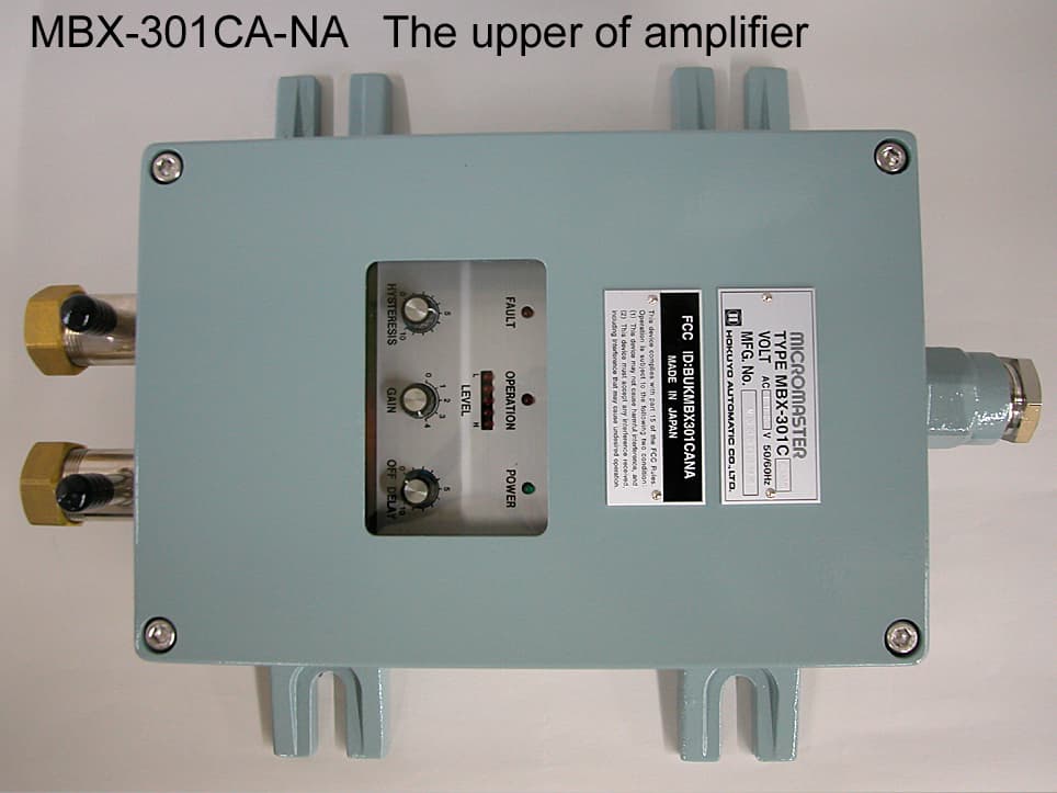
Click to zoom
Application Details
- Equipment Class
- FDS - Part 15 Field Disturbance Sensor
- Date of Grant
- Oct 17, 2004
- Application Purpose
- Original Equipment
- Date of Application
- Oct 17, 2004
- Equipment Note
- Field Disturbance Sensor
- Frequency Range
- 10525.00000000 - 10525.00000000
- Company
- Hokuyo Automatic Co Ltd
- Country
- Japan
Documents & Files
Document Text
Text extracted from the exhibit documents filed with the FCC. Open a document above to read the original.
Users Manual
HOKUYO AUTOMATIC CO.,LTD. May 1st’04 Be sure to read this instruction manual carefully before using to make correct operation of this device. Be sure to read this instruction manual and keep properly. Symbol Amended reason PagesDate Corrector Amended No. Approved by Checked by Drawn by Designed by Title Waveguide Type Micro Master MBX-301CA-NA Instruction Manual YUTANI YUTANI HOSHINO HOSHINO Drawing No. C-91-315 1/24 INSTRUCTION MANUAL WAVEGUIDE TYPE MICRO MASTER MBX-301CA-NA HOKUYO AUTOMATIC CO.,LTD. - NOTICE - ○ Please keep this instruction manual on the side of operator and maintenance person. For the detailed warranty and contact items , refer to 「AGREEMENT」 of this product. ○ Only properly trained & educated person for operation and maintenance of this device and also bearer of qualifications specified in the law shall operate this device. ○ Be sure to read this instruction manual & relative documents before installation, operation and maintenance operate correctly in accordance with the directions on the knowledge of the device, information for safety, operation & handling method of this device. ○ Keep always the scope of this various specification described on the instruction manual and execute correct maintenance to prevent possible malfunction. ○ Please prohibit the operation and handling which aren't described on the instruction manual, using of the spare parts out of our supplies, remodeling, improper usage and operation not pursuant to the instruction of instruction manual. It may cause malfunction or personal injury. We shall not fully responsible for accident it may occur by such breaches. ○ When you have incomprehensible item, question and unclear point, please contact to our branch office referred the last page. ○ On the contents of this instruction manual we have intellectual property right. The contents may not, in whole or part be revealed to any third party without prior written consent from us. ○ The contents in this instruction manual is subject to change without pre-notice for the purpose of improvement of the device. ○ If in case of happening inactivity or malfunction, please contact to our referred branch office with the following information. ・The contents of relative name plate or specifications(model name, production No., type, production date etc.) ・Abnormal condition(more in detail including condition before & after) ・Contact our offices which are mentioned in last page. 〇 FCC statement CAUTION USER : Changes or modifications not expressly approved by the party responsible for compliance could void the user’s authority to operate the equipment. The antenna must be located greater than 20cm from the user. Notice of safety Be sure to read carefully this instruction manual and relative documents before installation, operation and maintenance of this device to operate correctly. Operate this device only after acquainting yourself all with knowledge of device, safety notice & caution items. This instruction manual classifies caution items rank as 「Danger」「Caution」「Prohibition」 and 「Enforcement」. . Title Waveguide Type Micro Master MBX-301CA-NA Instruction Manual Drawing No. C-91-315 2/24 DANGER CAUTION PROHIBITION Possible to cause a danger situation if misused and might be dead or critical injury Possible to cause a danger situation if misused and might be harmed middle injury or slight injury or caused only physical damage Supposed to cause a possible danger if misused and inform an action prohibited. Supposed to cause a possible danger if misused and inform an action enforced. ENFORCEMENT HOKUYO AUTOMATIC CO.,LTD. Notice of safety(to be continued) About statement of above CAUTION however, it is possible to cause more serious result according to situation. keep the above mentioned notice without fail since these are very important. * The critical injury stated above means causing after effect by loss of eyesight, injury, burn(high temperature, low temperature), electric shock, fracture, poisoning etc., and necessity of hospitalization or long time attending to hospital for care. The middle injury or slight injury means injury, burn, electric shock etc. which are not necessary of hospitalization or long time attending to hospital for care. The physical damage means damage of property and equipment and enlarged damage relevant to damage of equipment. These notice for safety informs more important supplementary contents regarding to safety of Hokuyo Waveguide Type Micro Master. The customers should establish the safety measure according to various standards and criteria for the sake of safety operation and maintenance of equipment and device. The following danger mark is for Hokuyo Waveguide Type Micro Master. If this danger instruction may not be kept, it is possible to cause an accident resulting injury or death. Please note that the order of this instruction is never adopted order in important level and all instructions stated here are important. DANGER Pages * Take caution to handle the device and don't hit against or drop off the control box. There is some possibilities to cause an accident resulting injury and cause any malfunctions. * Don’t hit against or drop off the antenna. There is some possibilities to cause an accident resulting injury and cause any malfunctions. * In order to avoid danger of electric shock, ensure the power source is off when installation, maintenance and inspection. * In order to avoid danger of electric shock, don’t touch with exposed charging part. 14 15 19 22 The following caution mark is for Hokuyo Waveguide Type Micro Master. If this caution instruction may not be kept, it is possible to cause an accident resulting injury or death. Please note that the order of this instruction is never adopted order in important level and all instructions stated here are important. CAUTION Pages * Read this instruction manual carefully to operate safely. * Be sure to reach the instruction manual to final user. * Be sure to keep the instruction…
Text truncated - open the document above for the full version.
Block Diagram
× 更新年月日 D E S I G N 4 × 設 計 普通公差 △ 2 △△ 作 成 TITLE 図 番 AMENDED DATE AMENDED REASON 外 形 図 PARTICULARS OF DRAWING × D A T E 設計者 3 △ × TOLERANCE 1 1 : 1 DESIGNED PROJECTION 投 影 法 DRAWING 訂 正 箇 所 尺 度 CHECKED 図 修 番 号 AMENDED POINTS SCALES APPROVED AMENDED NO. 図 歴 年 月 日 CORRECTOR APPLY “JIS B 0405-vL-E”IF NOT SPECIFIED指示なき寸法公差は JIS B 0405-vL-E を適用する 訂 正 年 月 日 承 認名 称確 認 DR. NO. 訂 正 理 由 訂 正 者 RENEW DATE M1:UPC4570HA(B) Low-frequency SW1 M3:TC4051BP RY1 VR3 M1:UPC4570HA(A) Buffer MO86571 VR1 M2:TC4S66F Detector Hysteresis Variable attenuator Detecting output M7:LM78L12ACZ M4:HA2103B Waveguide 12.5m MD-90-188A Rectification Trouble output Control box MBX-301CA Transmission/reception system diagram Sep.4th'03 Sep.4th'03 Tranformer RS1:S1VB60 Voltage LED1:TLR124 D5:S5566B LED8:TLG124A Voltage Waveguide 12.5m Receiving antenna 3kHz stabilization Transmitting antenna 10.525GHz synchronous detection/ Low-frequency oscillation stabilization operating changeover 3kHz Hoshino AC200~220V Level meter M6:BA6154 PC1:PC752 Receiving circuit power 12VDC Transmitting circuit power 12VDC 10.525GHz 0V LED2~6:TLR124 Output delay/ SW2 Amplification/ M9:BA335 Amplification/ Q1:2SC1645S Trouble output MO86751A Q2:2SC2458Y M5:LR381086T1 Detecting output Modulation VR2 D4:1S2076A ZD1:RD18E Gunn D2:1S2076A Q4:2SC2458YLED7:TLR124 D3:1S2076A Power lamp AC100~110V D1:1S2076A M8:UPC78M12AHF SW3 detection oscilator Q3:2SC2458Y adjustment Stop to modulate RY2 amplification PC2:TLP-521-1 E.YutaniE.Yutani T.Hoshino
ID Label/Location Info
メッキ 化成処理 外面 内面 光沢塗 装 訂 正 箇 所 訂 正 理 由 訂正年月日 訂 正 者 指 示 ナ キ 角 縁 ハ 糸 面 取 リ ノ 事 品 番 品 名 表面処理 一般公差 図 修 番 号 図 歴 名 称 承 認 図 番 適用規格 有・半・無 着 色 アルマイト ( 白 ・ 黒 ) リューブライト・黒染め 尺 度 投 影 法 摘 要材 質 確 認 設 計 年 月 日 設 計 者 : 更新年月日 クロメート〔 ユニクロ(白) ・ 有色 ( 黄 ・ 黒 ) 〕 ・ ニッケル ・ クロム △ △ △ △ 1 2 3 4 × × × × 1 様式 2 作 成 (中級)精級 並級 粗級 P-00-001 MADE IN JAPAN This device complies with part 15 of the FCC Rules. (1) This device may not cause harmful interference, and (2) This device must accept any interference received, 導波管式ミクロマスタ 64 60 66 1 12 15 15 30 including interference that may cause undesired operation. 2 2-φ2.3 2.ハッチ部の文字:黒地に白貫文字 3.ハッチ部以外の文字:黒色 地:横ヘアラインアルミ地 t1 A1070P-H24 FCC ID:BUKMBX301CANA 1.文字は全てゴシック体 M80340 FCC認識銘板 2004.7.27 星野 2004.7.27 E-98-410A Operation is subject to the following two conditions : 前 嶋 末 国 星 野
Test Report
A-013-04-C Page 1 of 21 FCC ID : BUKMBX301CANA KEC Ikoma Testing Laboratory 12128 Takayama-cho Ikoma-city Nara 630-0101 Japan KANSAI ELECTRONIC INDUSTRY DEVELOPMENT CENTER HEAD OFFICE IKOMA TESTING LABORATORY 6-8-7 NISHITENMA 12128 TAKAYAMA-CHO KITA-KU OSAKA 530-0047 JAPAN IKOMA-CITY NARA 630-0101 JAPAN Corporate Juridical Person TEST REPORT Report No.A-013-04-C Date: 20 August 2004 This test report is to certify that the tested device properly complies with the requirements of: FCC Rules and Regulations Part 15 Subpart C Intentional Radiators. All the tests necessary to show compliance to the requirements were performed and these results met the specifications of requirement. The results of this report should not be construed to imply compliance of equipment other than that, which was tested. Unless the laboratory permission, this report should not be copied in part. 1. Applicant Company Name : Hokuyo Automatic Co., LTD. Mailing Address : 1-10-9, Nitaka, Yodogawa-ku, Osaka 532-0033 Japan 2. Identification of Tested Device Type of Device : Transmitter Kind of Equipment Authorization : : DoC : Certification : Verification FCC ID : BUKMBX301CANA Device Name : Waveguide Type MICROMASTER Trade Name : MICROMASTER Model Number : MBX-301CA-NA Serial Number : N0400299 : Prototype : Pre-production : Production Date of Manufacture : August 2004 3. Test Items and Procedure : AC Power Line Conducted Emission Measurement : Radiated Emission Measurement Above all tests were performed under: ANSI C63.4 – 2001 : without deviation, : with deviation(details are found inside of this report) 4. Date of Test Receipt of Test Sample : 17 August 2004 Condition of Test Sample : : Damage is not found on the set. : Damage is found on the set. (Details are described in this report) Test Completed on : 17 August 2004 Seiichi Izumi General Manager/ Ikoma Testing Laboratory A-013-04-C Page 2 of 21 FCC ID : BUKMBX301CANA KEC Ikoma Testing Laboratory 12128 Takayama-cho Ikoma-city Nara 630-0101 Japan Table of Contents 0. LABORATORY ACCREDITATION AND MEASUREMENT UNCERTAINTY ................ 3 0.1. Laboratory Accreditation .............................................................................................. 3 0.2. Measurement Uncertainty............................................................................................ 3 1. CERTIFICATION OF THE COMPLIANCE ..................................................................... 3 2. GENERAL INFORMATION .............................................................................................. 4 2.1. Product Description.......................................................................................................4 2.2. Description for Equipment Authorization .................................................................... 5 2.3. Test Facility ................................................................................................................... 5 3. TESTED SYSTEM ............................................................................................................. 6 3.1. Test Mode ....................................................................................................................... 6 3.2. Characteristics of Emission wave form ........................................................................ 6 3.3. Block Diagram of EUT System ..................................................................................... 7 3.4. Characterization and condition of EUT System .......................................................... 7 3.5. List of EUT System ....................................................................................................... 8 3.6. List of Cables ................................................................................................................. 8 4. AC POWER LINE CONDUCTED EMISSION MEASUREMENT ................................... 9 4.1. Test Procedure ............................................................................................................... 9 4.2. Test Configuration ....................................................................................................... 10 4.3. Test Results ................................................................................................................. 11 5. RADIATED EMISSION MEASUREMENT .................................................................... 15 5.1. Test Procedure ............................................................................................................. 15 5.2. Test Configuration ....................................................................................................... 16 5.3. Test Results ................................................................................................................. 17 6. USED TEST EQUIPMENTS AND CALIBRATION STATUS ........................................ 20 A-013-04-C Page 3 of 21 FCC ID : BUKMBX301CANA KEC Ikoma Testing Laboratory 12128 Takayama-cho Ikoma-city Nara 630-0101 Japan 0. LABORATORY ACCREDITATION AND MEASUREMENT UNCERTAINTY 0.1. Laboratory Accreditation KEC is accredited by the National Voluntary Laboratory Accreditation Program (NVLAP) for the specific scope of accreditation under Lab Code: 200207-0. When the test report concerns with the NVLAP accreditation test, the first page of the test report is signed by NVLAP Approved Signatory accompanied by the NVLAP logo. The report must not be used by the client to claim product endorsement by NVLAP or any agency of the U.S. Government. 0.2. Measurement Uncertainty The result of a measurement is only an approximation or estimate of the value of a specific quantity. And thus the measured is complete only when a statement of uncertainty is given. KEC quotes Measurement Uncertainty (U) of +/- 4.9 dB for Radiated Emissions of +/- 2.2 dB for Conducted Emissions 1. CERTIFICATION OF THE COMPLIANCE This test report is to certify that the tested device properly complies w…
Text truncated - open the document above for the full version.
Test Setup Photos
A-013-04-C Page 1 of 5 FCC ID : BUKMBX301CANA KEC Ikoma Testing Laboratory 12128 Takayama-cho Ikoma-city Nara 630-0101 Japan 1. APPENDIX Photographs of EUT System Configuration Tested Item Conducted Emission Measurement Test Mode 1 A-013-04-C Page 2 of 5 FCC ID : BUKMBX301CANA KEC Ikoma Testing Laboratory 12128 Takayama-cho Ikoma-city Nara 630-0101 Japan - Continued - Test Mode 2 A-013-04-C Page 3 of 5 FCC ID : BUKMBX301CANA KEC Ikoma Testing Laboratory 12128 Takayama-cho Ikoma-city Nara 630-0101 Japan Tested Item ・Radiated Emission measurement Test Mode 1 A-013-04-C Page 4 of 5 FCC ID : BUKMBX301CANA KEC Ikoma Testing Laboratory 12128 Takayama-cho Ikoma-city Nara 630-0101 Japan - Continued – Test Mode 2 A-013-04-C Page 5 of 5 FCC ID : BUKMBX301CANA KEC Ikoma Testing Laboratory 12128 Takayama-cho Ikoma-city Nara 630-0101 Japan Tested Item ・Emission Bandwidth measurement
Contact Information
Applicant
Makoto Hiraki(Foreign Trade Manager)
Test Firm
Kansai Electronic Industry Dev. Ct.Eizo Hariya
Technical Specifications
| # | Rule Parts | Frequency Range | Power Output |
|---|---|---|---|
| 1 | 15.245 | 10.53 GHz - 10.53 GHz | - |
Other Applications from Hokuyo Automatic Co Ltd
BUKMBX301CHITACHI
Jul 09, 1998FDS - Part 15 Field Disturbance Sensor
Equipment Class
FDS - Part 15 Field Disturbance Sensor