BZ6SEA245SEA 245 MF/HF DSC Marine Radiotelephone
SEA Inc of Delaware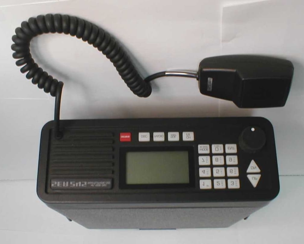
Click to zoom
Application Details
- Equipment Class
- GMF - Part 80 MF Transmitter (GMDSS)
- Date of Grant
- Sep 05, 2001
- Application Purpose
- Original Equipment
- Date of Application
- May 30, 2001
- Equipment Note
- SEA 245 MF/HF DSC Marine Radiotelephone
- Frequency Range
- 4.00000000 - 29.99900000
- Company
- SEA Inc of Delaware
- Country
- United States
Documents & Files
Document Text
Text extracted from the exhibit documents filed with the FCC. Open a document above to read the original.
Users Manual
FIRST DRAFT 10-7-99 V1.01 4-10-00 V1.02 10-20-00 V1.03 12-1-00 V1.04 2-2-01 V1.05 5-31-01 SEA INC OF DELAWARE PRELIMINARY MAINTENANCE MANUAL MF/HF SSB GMDSS RADIOTELEPHONE/DSC CONTROLLER MODEL SEA 245 (c) Copyright 2001 SEA, Inc. All rights reserved. SEA, Inc. 7030 220th St. S.W. Mountlake Terrace, Washington 98043 (425) 771-2182 FAX: (425) 771-2650 ta8man.docPage iiFCCID: BZ6SEA245 **IMPORTANT** NOTICE TO INSTALLERS ------------------------------------------------------------------- NOTE: The safe compass distance for this equipment (As defined in Paragraph 29 of IEC Publication 92-101, Third Edition): SEA 245 SINGLE SIDEBAND TRANSCEIVER = 2.0 meters ------------------------------------------------------------------- ta8man.docPage iiiFCCID: BZ6SEA245 TABLE OF CONTENTS 1GENERAL INFORMATION .............................................................................................................................. 1-1 1.1DESCRIPTION ................................................................................................................................................... 1-1 1.2EQUIPMENT FURNISHED .............................................................................................................................. 1-2 1.3TRANSCEIVER UNIT SPECIFICATIONS ...................................................................................................... 1-2 1.4MECHANICAL INFORMATION ..................................................................................................................... 1-2 1.5ELECTRICAL SPECIFICATIONS: ................................................................................................................... 1-2 2OPERATION ......................................................................................................................................................... 2-1 2.1WARM UP CAUTION ....................................................................................................................................... 2-1 2.2FRONT PANEL CONTROLS ............................................................................................................................ 2-1 2.3PROPAGATION ................................................................................................................................................. 2-1 2.4BANDWIDTH LIMITATIONS ......................................................................................................................... 2-2 3MODE AND FREQUENCY CONTROL ........................................................................................................... 3-1 3.1GENERAL ........................................................................................................................................................... 3-1 3.2SEA 245 FREQUENCY LISTING ..................................................................................................................... 3-2 3.3CAUTION! FREQUENCY TOLERANCE .................................................................................................... 3-47 3.4SETTING THE TRANSMITTER FREQUENCIES ....................................................................................... 3-48 4INSTALLATION ................................................................................................................................................... 4-1 4.1MOUNTING THE TRANSCEIVER .................................................................................................................. 4-1 4.2A TYPICAL INSTALLATION .......................................................................................................................... 4-1 4.3THE TRANSCEIVER UNIT REAR PANEL CONNECTION AND FUSES .................................................. 4-1 4.4FUSING ............................................................................................................................................................... 4-4 4.5THE GROUND CONNECTION ........................................................................................................................ 4-5 5THEORY OF OPERATION ................................................................................................................................ 5-1 5.1GENERAL ........................................................................................................................................................... 5-1 5.2THE RECEIVER ................................................................................................................................................. 5-1 5.3THE TRANSMITTER ........................................................................................................................................ 5-7 5.4THE MASTER CLOCK OSCILLATOR AND SYNTHESIZER SYSTEM ................................................. 5-11 5.5THE 2187.5 K H Z MONITOR RECEIVER ...................................................................................................... 5-14 5.6THE POWER SUPPLY CIRCUIT .................................................................................................................. 5-18 5.7THE MAINBOARD CONTROLLER AND DSP PROCESSORS ................................................................ 5-21 6THE SEA 245 FRONT PANEL/CONTROLLER SYSTEM ........................................................................... 6-1 6.1GENERAL ........................................................................................................................................................... 6-1 6.2THEORY OF OPERATION ............................................................................................................................... 6-1 ta8man.docPage ivFCCID: BZ6SEA245 LIST OF FIGURES 2.1 FRONT VIEW OF SEA 245 ............................................................................................................................... 2-1 5.2.1 RECEIVER BLOCK DIAGRAM ....................…
Text truncated - open the document above for the full version.
Block Diagram
ta4blkdiag.doc1FCCID: BZ6SEA245 Receiver Block Diagram SEA 245 Figure 5.2.1 HI-PASS ANT TX/RX PA/FILTER BOARD LOW PASS BAND SELECT ASY-0245-02 LOW PASS Q2 RF GAIN CTL 45-75 MHz 1st LO U1 2nd LO 45.040 MHz MIX-1 MIX-2 U3 U2 FL-1 FL-2 I.F. U5 45 MHz 40 KHz U34 A/D U1 CODEC U7 DSP U31 B/C ASY-0245-01MAINBOARD ASY-0245-03 FRONT PANEL/CONTROLLER BOARD SQL CPU BOARD ASY-0245-04 VOLUME Q6 U14 SPKR U10 ta4blkdiag.doc2FCCID: BZ6SEA245 Transmitter Block Diagram Figure 5.3.1 SEA 245 I MIC U10/DC CONTROLLER ASY-0245-03 U31A DSP U1 CODEC U7 45-75 MHz 1st LO Q MAINBOARDASY-0245-01 PA/FILTER Q1 Q2Q3 45.016 MHz 90° 2nd LO Q6Q7 LOW PASS Q3 45MHz FL1 Q5 Q4 MIX-1 TX/RX PA/FILTER ASY-0245-02 BAND SELECT ANT ta4blkdiag.doc3FCCID: BZ6SEA245 SEA 245 Synthesizer Block Diagram Figure 5.4.1 U21 12.288MHz Q19,Q20 SWITCH Q21,Q22Q23,Q24 BAND SYNDATA CS2 SYNCLK UNLK U17 SYNCLK CS1 SYNDATA 12.288MHz U22A/B TO CPU U24 U39A/B 90-150MHz 2 45-75MHz 1st LO TO MIX-1 U23 Q12Q13 U18AU18B CR24 45.04/45.016MHz Q33 TX ENABLE 45.04MHz TO MIX-2 2nd LO U25 MASTER CLK 12.288MHz TRIM CLK Y2 U9 C56 +12VS OVE1 45.016MHz TO I/Q MODULATOR, U6 ta4blkdiag.doc4FCCID: BZ6SEA245 Figure 5.5.1 SEA 245 2187.5 KHz MONITOR BLOCK DIAGRAM FILTER BANDPASS ANTENNA SEA 7002 or 2187.5KHz +12VRX Q9 GAIN CONTROL L20 MIX-3 Q10 FL-3 Q11 MIX-4 L26 C107 U15 U7A/B TO ADC @ 14.583KHz 2 U10B QQ U10A U12B 3 U12A U13 U14 C116 ADJ CLK Y1 5285.0 KHz 880.833 KHz U11 2642.5 KHz 7002 ANT. 455KHz 2 440.4167 KHz ta4blkdiag.doc5FCCID: BZ6SEA245 U36U38U37 Power Distribution Block Diagram Figure 5.6.1 SEA 245 Q26 12VSW Q29 U35 Q6,Q7 - +3.3V +12TX(PA) Q12 14 +10V J6 13 J8 +10VTX +10VTX +5V +5V Q30 +12VRX +12TX +5V Q28 9 MAINBOARD (ASY-0245-01) TXINT TXEN 10 RXEN RX + ASY-0245-03 ON/OFF J9 + - CONTROL 2 1 3 - DC/DC 24/12V CONV. 5 4 J10 Q15 F3,5A TX U3 CHASSIS PA GND -12VSW +12VSW CR2 F2,5A U4 +12VSW ~ U5 CHASSIS 5,67,8 GND 12VSW +12VSW PA/FILTER CHASSIS (ASY-0245-02) +9V Q8,Q9 BIAS BIAS J6 +24VDC J7 + F1,15A CR1 +24VCC Q2,Q3 Q1,Q4,Q5 Q14 +5VAD +5V ta4blkdiag.doc6FCCID: BZ6SEA245 SEA 245 Processor Assembly Block Diagram Figure 5.7.1
Cover Letter(s)
FCC IDENTIFIER BZ6SEA245 30 May, 2001 Federal Communications Commission Equipment Approval Services PO Box 358315 Pittsburgh, PA 15251-5315 Dear Sir or Madam, Enclosed is a certification submission for the SEA 245 MF/HF SSB marine radiotelephone with DSC. In addition to the electronic form 731, the fee and voucher (sent separately), and this letter the following file attachments are included: FILEDESCRIPTION ta1labeldwg245.pdfDrawings showing FCC ID label and its placement on rear panel ta2jmestmt1.pdfSigned statement of test supervisor (Jim Elder) ta2jmestmt2.pdfSigned statement of project engineer (Jim Elder) concerning DSC compliance ta3extphotos.pdfExternal photos (front and rear) of equipment ta4blkdiag.pdfFunctional block diagrams of equipment (excerpted from manual) ta5schem24501.pdfSchematic diagram of main board (4 sheets) ta5schem24502.pdfSchematic diagram of power amplifier board (2 sheets) ta5schem24503.pdfSchematic diagram of front panel controller board (2 sheets) ta5schem24504.pdfSchematic diagram of CPU/DSP board (2 sheets) ta6testrpt245.pdfTest report containing general information, technical description of the equipment and a description of the procedures, setups, requirements, and results of all required technical tests ta6sitedata.pdfDescription of field site used for measuring field strength of spurious radiation ta8man.pdfPreliminary user’s manual containing equipment specifications, operational instructions, theory of operation, and tuneup procedures ta9intphotos.pdfInternal photos of equipment ta10bom.pdfParts list for the radio ta10tuneup.pdfExcerpt from preliminary user’s manual containing tuneup procedures ta12theoryop.pdfExcerpt from preliminary user’s manual containing theory of operation I appreciate your attention to this certification request. Should you require further information regarding this application, please contact me at (425)-771-2182. For your greater convenience the SEA Inc. WATS line number is 1-800-426-1330. Sincerely, Jim Elder Marine Engineering Manager SEA, Inc. of Delaware
External Photos
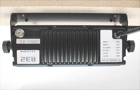
ta3extphotos.docFCC ID: BZ6SEA245 SEA 245 FRONT VIEW SEA 245 REAR VIEW
ID Label/Location Info
SAMPLE FCC LABEL FOR SEA 245 PER FCC 2.925 (a) SAMPLE GMDSS LABEL FOR SEA 245 PER FCC 80.1103 (e) REAR PANEL DRAWING OF SEA 245 SHOWING LABEL LOCATIONS (NOT TO SCALE) FCC ID: BZ6SEA245 24 V DC 51 P2P3 25 ACCESSORY CONNALARM / NMEA 14 S/N: SEA 245 PRINTER 13 TM FCC ID: BZ6SEA245 MADE IN U.S.A. ALARM ACK OUT 1 LO12VSWHIALARM RQ IN 1 NMEA IN HILO 8 1 NMEA OUT TXAFGNDLLAF2187.5 ANTDMDTUNE TND ANTENNA 50 OHMS ® MICAFSPKRHANDSETGND 12VSW PTTGND (AF) 14 RS-232 69 - P1 SEABUSS TM CHASSIS GNDPTT12VSWGND 1 AF DATA P10 9 + GND
Internal Photos
ta9intphotos.docFCC ID: BZ6SEA245 SEA 245 INTERNAL TOP VIEW SEA 245 INTERNAL BOTTOM VIEW
Operational Description
i SEA INC OF DELAWARE PRELIMINARY MAINTENANCE MANUAL EXCERPTS ON THEORY OF OPERATION MF/HF SSB GMDSS RADIOTELEPHONE/DSC CONTROLLER MODEL SEA 245 (c) Copyright 2001 SEA, Inc. All rights reserved. SEA, Inc. 7030 220th St. S.W. Mountlake Terrace, Washington 98043 (425) 771-2182 FAX: (425) 771-2650 ii TABLE OF CONTENTS 5THEORY OF OPERATION ................................................................................................................................ 5-1 5.1GENERAL ........................................................................................................................................................... 5-1 5.2THE RECEIVER ................................................................................................................................................. 5-1 5.3THE TRANSMITTER ........................................................................................................................................ 5-7 5.4THE MASTER CLOCK OSCILLATOR AND SYNTHESIZER SYSTEM ................................................. 5-11 5.5THE 2187.5 K H Z MONITOR RECEIVER ...................................................................................................... 5-14 5.6THE POWER SUPPLY CIRCUIT .................................................................................................................. 5-17 5.7THE MAINBOARD CONTROLLER AND DSP PROCESSORS ................................................................ 5-20 6THE SEA 245 FRONT PANEL/CONTROLLER SYSTEM ........................................................................... 6-1 6.1GENERAL ........................................................................................................................................................... 6-1 6.2THEORY OF OPERATION ............................................................................................................................... 6-1 LIST OF FIGURES 5.2.1 RECEIVER BLOCK DIAGRAM ....................................................................................................................... 5-2 5.3.1 TRANSMITTER BLOCK DIAGRAM .............................................................................................................. 5-6 5.4.1 SYNTHESIZER BLOCK DIAGRAM .............................................................................................................. 5-12 5.5.1 2187.5 KHZ MONITOR BLOCK DIAGRAM ................................................................................................ 5-14 5.6.1 POWER DISTRIBUTION BLOCK DIAGRAM ............................................................................................ 5-17 5.7.1 MAINBOARD CPU AND DSP BLOCK DIAGRAM .................................................................................... 5-20 5 5-1 5 THEORY OF OPERATION 5.1 GENERAL The SEA 245 is a double conversion MF/HF SSB transceiver of up conversion design. The first intermediate frequency (IF) is 45 MHz and uses a relatively narrowband (8 kHz) crystal topping filter in conjunction with front end low and high pass filters to provide excellent image, spurious and harmonic rejection. This type of broadband design results in a minimum of tuned circuits. The second intermediate frequency of approximately 40 kHz permits the use of DSP oversampling techniques to provide secondary selectivity. Receiver baseband recovery uses IF based DSP circuitry. The filtered, downconverted 40 kHz IF signal is fed into the ADC and DSP circuitry provides programmable receiver filtering and demodulation. Transmitter baseband generation is likewise DSP based and uses the DSP/CODEC circuitry and an I/Q modulator, together with an appropriate DSP algorithm to generate the desired baseband signal at 45 MHz. The frequency control circuitry in the SEA 245 uses a combination of two PLL- based frequency synthesizers and the system DSP engine to provide the various frequency conversions. The first conversion oscillator is the 90-150 MHz VCO, which uses a PLL-based loop with a reference of 8 kHz. This oscillator is then divided by two to 45-75 MHz. The resulting coarse-tuned local oscillator has a resolution of 4 kHz, very fast settling time and a low noise floor. The second conversion VCO operates at 45.040 MHz. In the transmit mode, the VCO operates at 45.016 MHz for the transmitter I/Q modulator circuitry. The loop reference frequency is 8 kHz. All frequency determining circuitry is locked to the master clock oscillator, a 12.288 MHz OCXO. The SEA 245 operating system resides in the Front Panel/Controller Assembly. The operator communicates with the operating system firmware through the 18 key keypad. The Front Panel/Controller Assembly is actually a SEAbuss(c) Controller designed to communicate with the Mainboard Controller through the standard SEABUSS interface. The SEA 245 SEABUSS is designed to support a single SEA 2450 Remote Controller in addition to the Front Panel. 5.2 THE RECEIVER 5-2 Receiver Block Diagram SEA 245 Figure 5.2.1 HI-PASS ANT TX/RX PA/FILTER BOARD LOW PASS BAND SELECT ASY-0245-02 LOW PASS Q2 RF GAIN CTL 45-75 MHz 1st LO U1 2nd LO 45.040 MHz MIX-1 MIX-2 U3 U2 FL-1 FL-2 I.F. U5 45 MHz 40 KHz U34 A/D U1 CODEC U7 DSP U31 B/C ASY-0245-01MAINBOARD ASY-0245-03 FRONT PANEL/CONTROLLER BOARD SQL CPU BOARD ASY-0245-04 VOLUME Q6 U14 SPKR U10 5-3 5.2.1 BLOCK DIAGRAM Figure 5.2.1 shows the block diagram of the receive mode. The received RF signal is routed from the rear panel antenna jack to a low pass filter selected by a relay bank on the PA/Filter Assembly (ASY-0245-02). The output of the filter is routed from J4 on the PA/Filter Assembly through a coaxial cable to the receiver input circuitry on the Mainboard Assembly (ASY-0245-01). The signal is further bandpass filtered to reject interfering signals and input to the RF preamplifier/attenuator, Q2. In the "on" state, the amplifier provides some 3-4 dB of low-noise preamplifier gain. In the "off" state, the stage becomes an attenuato…
Text truncated - open the document above for the full version.
Parts List/Tune Up Info
SEA245 BILL OF MATERIALS RefDesComponentComponent DescriptionLevel ASY-245245 BASIC RADIO ASSY (TESTED)1 PST-245245 BASIC RADIO ASSY (UNTESTED)2 P2/AHAR-0084-187JACK SCREW HX ZS 4-40X3/13 P2/BHAR-0084-187JACK SCREW HX ZS 4-40X3/13 ASY-0245-01MAINBOARD3 L28FAB-7001-05HI/LO VCO SHIELD4 L31FAB-7001-05HI/LO VCO SHIELD4 L33FAB-7001-05HI/LO VCO SHIELD4 L35FAB-7001-05HI/LO VCO SHIELD4 PST-0245-01MAIN BOARD (UNTESTED)4 C56CAP-0025-002CAPACITOR TRIMMER 2-10PF5 FIL1FIL-0020-001FILTER,XTAL,4 POLE,45MHZ, 2 PCS5 FL1AHAR-0029-010INSULATOR,MYLAR,3 HOLE,0.074IN SP5 FL1BHAR-0029-010INSULATOR,MYLAR,3 HOLE,0.074IN SP5 FL2FIL-0020-003FILTER,2 POLE,45MHZ (1/2 FIL-20-1)5 FL2HAR-0029-010INSULATOR,MYLAR,3 HOLE,0.074IN SP5 J8 TO J9CAB-0501-001MINI COAX CABLE, 70 MM5 L17ASY-0009-22IND,TOR 22T18-226 ON 9-15 L18ASY-0009-19IND,TOR 19T18-226 ON 9-15 L28ASY-0017-11IND,TOR 11T18-228 ON 12-25 L3ASY-0017-09IND,TOR 9T18-228 ON 12-25 L31ASY-0156-L3TOROID ASY, 10T #265 L33ASY-0156-L3TOROID ASY, 10T #265 L35ASY-0156-L3TOROID ASY, 10T #265 L4ASY-0017-09IND,TOR 9T18-228 ON 12-25 L5ASY-0017-08IND,TOR 8T18-228 0N 12-25 L73ASY-0022-14IND,TOR 14T18-228 ON 3-15 OVE1OVE-0005-004OVEN,75 DEG C,13 VDC, W/INSULATOR5 RX COAXASY-0235-C0614.5" COAX WITH PHONO PLUG5 T1ASY-0222-TT5INDUCTOR,T TRIFI ON #435 T2ASY-0222-TT5INDUCTOR,T TRIFI ON #435 T5ASY-0209-T1MTRANSFORMER5 TX COAXASY-0235-C0710.875" COAX WITH PHONO PLUG5 Y1CRY-0019-005CRYSTAL,5.285MHZ 25C 20PF 3LEG5 Y1HAR-0029-011INSULATOR,MYLAR,3 HOLE,0.096IN SP5 Y2CRY-0028-002CRYSTAL,12.288MHZ @75C,HC43/U5 Y2HAR-0029-007CRYSTAL INSULATOR,MYLAR5 HAR-0106-003SHIELD,PCB,2.5X4.0X.8H5 STF-0245-01MAIN BOARD, STUFFED5 C116CAP-0076-002TRIMMER CAPACITOR,3-10PF,SEALED6 C146CAP-0027-104CAP,FILM,CK05,.1UF,100/63V,5-10%6 C147CAP-0027-104CAP,FILM,CK05,.1UF,100/63V,5-10%6 C149CAP-0037-012CAP, ELECT. 330UF RAD6 C181CAP-0027-224CAP,FILM,CK05,.22UF,100/63V,5-10%6 C183CAP-0027-473CAP,FILM,CKO5,.047UF,100/63V,5-10%6 C187CAP-0037-012CAP, ELECT. 330UF RAD6 C189CAP-0027-104CAP,FILM,CK05,.1UF,100/63V,5-10%6 C311CAP-0076-002TRIMMER CAPACITOR,3-10PF,SEALED6 ta10bom.xls1 of 33FCC ID:BZ6SEA245 SEA245 BILL OF MATERIALS C38CAP-0076-002TRIMMER CAPACITOR,3-10PF,SEALED6 C39CAP-0076-002TRIMMER CAPACITOR,3-10PF,SEALED6 C46CAP-0076-002TRIMMER CAPACITOR,3-10PF,SEALED6 C49CAP-0076-002TRIMMER CAPACITOR,3-10PF,SEALED6 C76CAP-0027-473CAP,FILM,CKO5,.047UF,100/63V,5-10%6 C77CAP-0027-473CAP,FILM,CKO5,.047UF,100/63V,5-10%6 FIL3FIL-0004-007FILTER, 455KHZ, +-2KHZ 6DB BW6 J1CON-0043-018SOCKET,SIP,1X32,.1"SP,.3"PCB SPACED6 J2CON-0043-018SOCKET,SIP,1X32,.1"SP,.3"PCB SPACED6 J3CON-0043-016SOCKET,SIP,1X20,.1"SP,.3"PCB SPACED6 J4SOC-0002-008IC SOCKET, 8 PIN DIP6 J5SOC-0002-016IC SOCKET, 16 PIN DIP6 J6SOC-0002-016IC SOCKET, 16 PIN DIP6 J7CON-0020-025D-SUB,9-PIN FEMALE,FERRITE,BRDLCK6 J8CON-0001-010JACK, MINI RF 90DEG6 J9CON-0001-010JACK, MINI RF 90DEG6 JU1CON-0240-0303 PIN SINGLE ROW HEADER6 L14ID-0022-270-16A.4 LS, 27UH6 L15IND-0022-471IND,470UH,MINI6 L20IND-0036-106IND,10UH+/-10%,7MM,VARIABLE COIL6 L22TRA-0014-002TRANSFORMER,455KHZ 7MM 1ST IF6 L23IND-0022-471IND,470UH,MINI6 L24IND-0022-471IND,470UH,MINI6 L25IND-0022-471IND,470UH,MINI6 L26IND-0022-471IND,470UH,MINI6 L6ID-0022-270-16A.4 LS, 27UH6 L7IND-0022-471IND,470UH,MINI6 MIX1MIX-0002-001DBL BAL MIXER6 P1CON-0061-0093.5MM PITCH RT ANGLE HEADER,9 PIN6 P2CON-0061-0143.5MM PITCH RT ANGLE HEADER,14 PIN6 P3CON-0070-008HEADER,2.5MM PITCH,RT ANGLE,8 PIN6 R252RES-0027-104TRIMMER, 100K6 R255RES-0027-104TRIMMER, 100K6 R77RES-0027-201TRIMMER, 200 OHM POT6 R78RES-0027-201TRIMMER, 200 OHM POT6 R85RES-0027-503RESISTOR, TRIMMER 50K6 T3TRA-0011-0047MM IF TRANSFORMER FOR 456 T4TRA-0011-0047MM IF TRANSFORMER FOR 456 U37SM-0109-001-13BFIXTURE #6 CUT, 78056 MSK-0245-01MAIN BOARD, MASKED6 SMT-0245-01QSMT-0245-01 QC'D7 SMT-0245-01MAIN BOARD SMT ASSY8 C1CAP-1206-222CAP,CER,SMD,.002UF,COG,50V,5%9 C10CAP-0805-104CAP,CER,SMD,.1UF,Y5V,25V,+80-20%9 C100CAP-0805-103CAP,CER,SMD,.01UF,X7R,50V,10%9 C101CAP-0805-104CAP,CER,SMD,.1UF,Y5V,25V,+80-20%9 C102CAP-1014-476CAP,TANT,SMD,47UF,16V,10%,CASE D9 C103CAP-0805-104CAP,CER,SMD,.1UF,Y5V,25V,+80-20%9 C104CAP-1206-105TCAP,TANCER,SMD,1UF,Y5V,25V,+80/-20%9 C105CAP-0805-103CAP,CER,SMD,.01UF,X7R,50V,10%9 ta10bom.xls2 of 33FCC ID:BZ6SEA245 SEA245 BILL OF MATERIALS C106CAP-0805-104CAP,CER,SMD,.1UF,Y5V,25V,+80-20%9 C107CAP-0805-103CAP,CER,SMD,.01UF,X7R,50V,10%9 C108CAP-0805-104CAP,CER,SMD,.1UF,Y5V,25V,+80-20%9 C109CAP-0805-104CAP,CER,SMD,.1UF,Y5V,25V,+80-20%9 C11CAP-0805-104CAP,CER,SMD,.1UF,Y5V,25V,+80-20%9 C110CAP-0805-103CAP,CER,SMD,.01UF,X7R,50V,10%9 C111CAP-0805-103CAP,CER,SMD,.01UF,X7R,50V,10%9 C112CAP-0805-103CAP,CER,SMD,.01UF,X7R,50V,10%9 C113CAP-0805-330CAP,CER,SMD,33PF,COG,50V,5%9 C115CAP-0805-150CAP,CER,SMD,15PF,COG,50V,5%9 C117CAP-0805-473CAP,CER,SMD,.047UF,X7R,50V,10%9 C118CAP-0805-104CAP,CER,SMD,.1UF,Y5V,25V,+80-20%9 C119CAP-0805-104CAP,CER,SMD,.1UF,Y5V,25V,+80-20%9 C12CAP-0805-104CAP,CER,SMD,.1UF,Y5V,25V,+80-20%9 C120CAP-1014-106CAP,TANT,SMD,10UF,16V,10%,CASE C9 C121CAP-1206-102CAP,CER,SMD,.001UF,NPO,100V,5%,BLUA9 C122CAP-1206-391CAP,CER,SMD,390PF,NPO,100V,5%9 C123CAP-1206-102CAP,CER,SMD,.001UF,NPO,100V,5%,BLUA9 C124CAP-1206-102CAP,CER,SMD,.001UF,NPO,100V,5%,BLUA9 C125CAP-1206-102CAP,CER,SMD,.001UF,NPO,100V,5%,BLUA9 C126CAP-1206-561CAP,CER,SMD,560PF,NPO,100V,5%9 C127CAP-1206-102CAP,CER,SMD,.001UF,NPO,100V,5%,BLUA9 C128CAP-1206-102CAP,CER,SMD,.001UF,NPO,100V,5%,BLUA9 C129CAP-1206-102CAP,CER,SMD,.001UF,NPO,100V,5%,BLUA9 C13CAP-0805-104CAP,CER,SMD,.1UF,Y5V,25V,+80-20%9 C130CAP-1206-471CAP,CER,SMD,470PF,NPO,100V,5%9 C131CAP-1206-270CAP,CER,SMD,27PF,NPO,100V,5%9 C132CAP-1206-101CAP,CER,SMD,100PF,NPO,100V,5%9 C133CAP-0805-221CAP,CER,SMD,220PF,COG,50V,5%9 C134CAP-0805R2H-150CAP,CER,SMD,15PF,TC,N220,50V,5%9 C135CAP-0805-330CAP,CER,SMD,33PF,COG,50V,5%9 C136CAP-0805-680CAP,CER,SMD,68PF,COG,50V,5%9 C137CAP-0805-103CAP,CER,SMD,.01UF,X7R,50V,10%9 C138CAP-0805-104CAP,CER,SMD,.1UF,Y5V,25V,+80-20%9 C139CAP-1014-106CAP,TANT,SMD,10UF,16V,10%,CASE C9 C14CAP-0805-103CAP,CER,SMD,.01UF,X7R,50V…
Text truncated - open the document above for the full version.
Parts List/Tune Up Info
i SEA INC OF DELAWARE PRELIMINARY MAINTENANCE MANUAL EXCERPTS CONCERNING TUNEUP MF/HF SSB GMDSS RADIOTELEPHONE/DSC CONTROLLER MODEL SEA 245 (c) Copyright 2001 SEA, Inc. All rights reserved. SEA, Inc. 7030 220th St. S.W. Mountlake Terrace, Washington 98043 (425) 771-2182 FAX: (425) 771-2650 ii TABLE OF CONTENTS 2OPERATION ......................................................................................................................................................... 2-1 2.1WARM UP CAUTION ....................................................................................................................................... 2-1 3MODE AND FREQUENCY CONTROL ........................................................................................................... 3-1 3.1GENERAL ........................................................................................................................................................... 3-1 3.2CAUTION! FREQUENCY TOLERANCE ....................................................................................................... 3-2 3.3SETTING THE TRANSMITTER FREQUENCIES .......................................................................................... 3-2 2-1 2 OPERATION 2.1 WARM UP CAUTION Do not attempt to transmit until the radiotelephone is warmed up for at least 1 minute. Transmitting before the 1-minute warm-up period has elapsed can cause violation of FCC regulations. 3-1 3 MODE AND FREQUENCY CONTROL 3.1 GENERAL In the SEA 245, the frequency of operation is determined through a combination of coarse and fine tuning mechanisms. The coarse tuning system consists of the PLL circuitry associated with the first Local Oscillator VCO. The effective loop frequency of the PLL is 4 kHz and the first LO is preset to the nearest incremental frequency needed to convert the desired operating frequency to 45 MHz. The required divide-by-N number for a given operating frequency is calculated by the control microprocessor and then loaded into the main loop PLL chip through the microprocessor SPI bus. The fine tuning system is incorporated into the DSP algorithm, which operates as the receiver “back end” and the transmitter "front end". The PLL that controls the second conversion oscillator is also loaded through the microprocessor SPI bus. Such data as filter band, VCO band, synthesizer loads, carrier status and DSP algorithm are calculated and stored in appropriate registers by the controller computer, once the desired channel is entered by the operator. 3.1.1 TRANSMITTER MODE SELECTION The primary mode of operation of the SEA 245 is in the J3E (SSB with fully suppressed carrier) mode. Two auxiliary VOICE modes are also provided: R3E: SSB with pilot carrier re-inserted 16 dB below PEP. H3E: SSB with pilot carrier re-inserted 6 dB below PEP. J3E is the basic SSB operating mode and is used for virtually all VOICE communications. H3E (AME) is used to provide a degree of compatibility between old style AM and SSB systems. Present practice limits this mode to 2182.0 kHz ONLY. R3E is primarily used to provide a pilot carrier on public correspondence channels. Present practice ignores this mode. J2B: TELEX operation with both internally and externally generated (AFSK) tones. Uses J3E mode with narrower bandpass filter. Note that the internal DSC system uses the same standard 1700 Hz subcarrier frequency as is used in the SEA 3000 SEATOR equipment. 3.1.2 RECEIVE MODE SELECTION The SEA 245 supports J3E, R3E and H3E modes as a standard SSB (J3E) receiver. The passband filter and AGC characteristics are tailored for SSB VOICE operation. In the TELEX (J2B) receive mode, the passband filter is shifted to narrowband (500 3-2 Hz) and the BFO offset is set to the International Standard of 1700 Hz. AGC is fast attack, fast release. In the CW (A1A) receive mode, the receiver passband filter is shifted to narrowband (500 Hz) and the BFO offset is set to 1000 Hz. AGC is fast attack, fast release. In the AM (A3E) receive mode, the receiver passband is shifted to maximum bandwidth (4 kHz) and the received signal carrier is offset 1 kHz from the passband center. The DSP based envelope detector provides "true" AM demodulation with an effective bandwidth of 3000 Hz for audio recovery. This mode is useful primarily in the reception of time signals from WWV, shortwave broadcast signal etc. AGC is fast attack, fast release. 3.2 CAUTION! FREQUENCY TOLERANCE Under FCC Rules, the frequency tolerance for the Marine Service is + 10 Hz. In order to achieve this accuracy a frequency counter with long term accuracy of + 1 Hz should be used. All work affecting the transmitter performance must be done by, or under the supervision of, a person holding at least a General Radiotelephone FCC license. 3.3 SETTING THE TRANSMITTER FREQUENCIES 3.3.1 THE MASTER CLOCK OSCILLATOR 1. Select the highest desired transmitter frequency (Such as 25083.0 kHz). With the transmitter output connected to an appropriate dummy load and a few watts of re- inserted carrier being generated, connect a high accuracy frequency counter (See Paragraph 3.3) to the RF dummy load and adjust trimmer capacitor C56 on the transceiver Main Board (ASY-0245-01) for the correct carrier frequency. The trimmer capacitor is located next to the Master Clock crystal oven on the Main Board Assembly. 3.3.2 ENABLING CARRIER REINSERTION Using DIRECT FREQUENCY ENTRY mode (See PP 2.5.28 above), enter the desired test frequency. E.g.: 25083.0 kHz. Select R3E from the MODE menu.
Schematics
MOUNTLAKE TERRACE, WA. USAPROPRIETARY TO SEA Inc.RESERVED. CONFIDENTIAL &SEA Inc. 1998 ALL RIGHTS C SHEET 1 of 2ASY-0245-02 REDRAWN INTO AutoCad 12/5/00 REVISION HISTORY MOUNTLAKE TERRACE, WA. USAPROPRIETARY TO SEA Inc.RESERVED. CONFIDENTIAL &SEA Inc. 1998 ALL RIGHTS C SHEET 2 of 2ASY-0245-02
Test Report
FCC 2.948(a)(b) “Description of Measurement Facilities” Norse Lab, Inc. 13830 Issaquah-Hobart Rd. Issaquah, WA 98027 ta6sitedata.docPage 2 of 11 FCC 2.993(a)(b)(1)FIELD STRENGTH MEASUREMENTS OF SPURIOUS RADIATION FCC 2.948(a)(b)Description of Measurement Facilities 1. Location of Test Site The test site chosen is located about 4 miles south of Issaquah, Washington at 13830 Issaquah-Hobart Rd. 2. Physical Description of Test Site The test site consists of an open grass field, surrounded on two sides by trees but otherwise open and free of structures. The site is located in the middle of a 12-acre plot of undeveloped land. Please see photographs (figures 1-6). 3. Drawing of Test Site Please see survey drawing (figure 7). 4. Description of Support Structures The signal source/D.U.T was supported by a wooden turntable, 1 meter above ground. The table is rotated manually. The spectrum analyzer was supported by a nonmetallic cart, 1 meter above ground and about 7 meters behind the receiving dipole antenna. The dipole antenna masts are made from heavy-duty PVC pipe and were supported by wood material. The receiving antenna height is manually adjustable by a sliding carriage. 5./6. List of Measuring Equipment, with Calibration Information DescriptionManufacturerModelS/NLast Cal Spectrum AnalyzerHP8568B2415A005223/01 Signal GeneratorFarnellPSG10001…
Text truncated - open the document above for the full version.
Contact Information
Applicant
G William Forgey(V.P Engineering)
425 771-2182Fax: 425 771-2650
Technical Contact
SEA Inc of DelawareJim Elder
[email protected]425-771-2182
7030 220th Street SW · Mountlake Terrace, Washington · United States
Technical Specifications
| # | Rule Parts | Frequency Range | Power Output | Emission | Tolerance |
|---|---|---|---|---|---|
| 8 | 80.1101(c)(4),87,9 | 4 MHz - 29.999 MHz | 150 W | 280HJ2B | 10 Hz |
Other Applications from SEA Inc of Delaware
BZ6SEA157
May 15, 2000VHF Marine Radiotelephone/DSC Controller
Equipment Class
TNB - Licensed Non-Broadcast Station Transmitter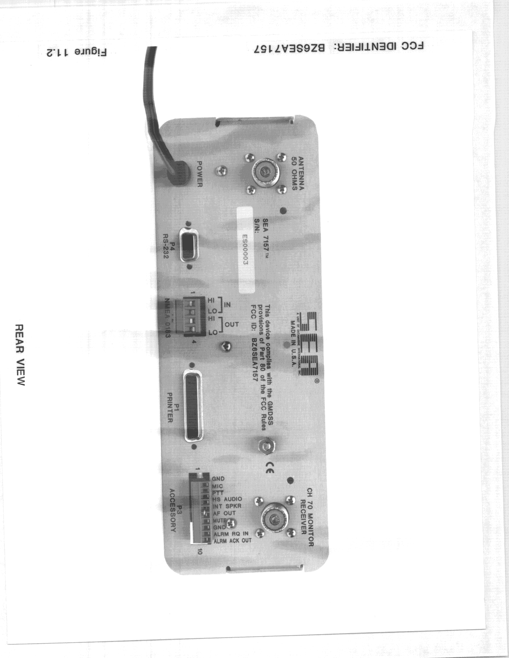
BZ6SEA7157
Oct 18, 1998GVH - Part 80 VHF Transmitter (GMDSS)
Equipment Class
GVH - Part 80 VHF Transmitter (GMDSS)BZ6ESP520DX
Mar 03, 1998TNB - Licensed Non-Broadcast Station Transmitter
Equipment Class
TNB - Licensed Non-Broadcast Station TransmitterBZ6SEA235
Oct 05, 1997Satifies Section 80-221
Equipment Class
TNB - Licensed Non-Broadcast Station TransmitterBZ6SEA6002
Apr 23, 1996CES - INMARSAT-C SES
Equipment Class
CES - INMARSAT-C SES