C3K-WKS268RF Module
Microsoft Corporation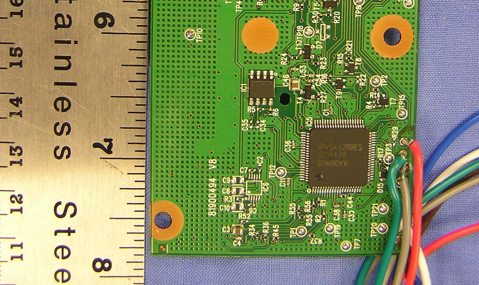
Click to zoom
Application Details
- Equipment Class
- DSS - Part 15 Spread Spectrum Transmitter
- Date of Grant
- Sep 12, 2005
- Application Purpose
- Original Equipment
- Date of Application
- Sep 12, 2005
- Equipment Note
- RF Module
- Frequency Range
- 2402.00000000 - 2482.00000000
- Company
- Microsoft Corporation
- Country
- United States
Documents & Files
Document Text
Text extracted from the exhibit documents filed with the FCC. Open a document above to read the original.
Users Manual
Important Safety Information Failure to properly set up, use, and care for the Xbox 360 video game and entertainment system can increase the risk of serious injury or death, or damage to the Xbox 360 video game and entertainment system. Read this manual and the manuals of any peripherals for important safety and health information. Keep all manuals for future reference. For replacement manuals, go to www.xbox.com/support or call the Xbox Customer Support number provided on the back cover. Before allowing children to use the Xbox 360 video game and entertainment system: 1. Determine how each child can use the Xbox 360 console (playing games, connecting to Xbox Live, replacing batteries, making electrical, AV cable, and network connections) and whether they should be supervised during these activities. 2. If you allow children to use the Xbox 360 console without supervision, be sure to explain all relevant safety and health information and instructions. This symbol identifies safety and health messages in this manual and Xbox 360 peripherals manuals. Your Xbox 360 Video Game and Entertainment System Thanks for purchasing your Xbox 360™ video game and entertainment system from Microsoft. You’re now at the center of a customizable experience that brings your games, your friends, and your digital entertainment together in one powerful package. • The Xbox 360 video game and entertainment system lets you play Xbox 360 games, DVD movies, and audio CDs. • With high-speed Internet service, connect to millions of gamers on Xbox Live®. Instantly be a part of a community where you can play together, talk to your friends, and download new content. • Stream pictures, music, and more to your Xbox 360 console by connecting to your Microsoft® Windows®-based PC or other devices such as digital cameras and portable music players. • Enjoy music and other content pre-installed with your Xbox 360 Hard Drive. For more information about the Xbox 360 Hard Drive, go to www.xbox.com . Select a Location for the Xbox 360 Console Prevent the Console from Falling If the Xbox 360 console falls and hits someone, especially a small child, it could cause serious injury. To reduce the risk of such injuries and damage to the Xbox 360 console, set it up according to these instructions and place it on a surface that: • Is flat and level. • Is stable and not likely to tip over. • Allows all four feet of the console to be in contact with the surface. • Is not likely to allow the console to slip or slide off. • Is clean and free of dust and debris. If the surface or console feet become dirty or dusty, clean them with a dry cloth. If the console is positioned vertically, put it on a surface where it is not likely to fall if it tips over. Arrange all cables and cords so that people and pets are not likely to trip over or accidentally pull on them as they move around or walk through the area. When the console is not in use, you may need to disconnect all cables and cords from the front and rear of the console to keep them out of the reach of children and pets. Do not allow children to play with cables and cords. Prevent the Console from Overheating Do not block any ventilation openings on the console or power supply. Do not place the console or power supply on a bed, sofa, or other soft surface that may block ventilation openings. Do not place the console or power supply in a confined space, such as a bookcase, rack, or stereo cabinet, unless the space is well ventilated. Do not place the console or power supply near any heat sources, such as radiators, heat registers, stoves, or amplifiers. Avoid Smoke and Dust Do not use the console in smoky or dusty locations. Smoke and dust can damage the console, particularly the DVD drive. Set Up Your Xbox 360 Video Game System Connect the Component HD AV Cable IMPORTANT Stationary images in video games can “burn” into some TV screens, creating a permanent shadow. Consult your TV owner's manual or manufacturer before playing games. To connect your Xbox 360 console to a TV with standard, composite input: 1. Connect the component HD AV cable connector to the AV port on the console. 2. Set the switch on the AV port connector to regular TV. 3. Connect the color-coded connectors to the corresponding jacks on the TV: yellow to yellow (video), red to red (right audio), and white to white (left audio). NOTE For monaural (mono) TVs, which have only one audio jack, connect either the right or left audio connector to the audio jack. 4. Select the appropriate video input on your TV (see "No Picture" under "Troubleshooting" on page ?? for further information). NOTE Your Xbox 360 Component HD AV Cable has two distinct sets of connectors on the TV end grouped by audio and video. Do not confuse the red connector from the audio group with the red connector from the video group. To connect your Xbox 360 console to a TV with component input: 1. Connect the Xbox 360 Component HD AV Cable connector to the AV port on the console. 2. Set the switch on the AV port connector to regular TV or HDTV. The HDTV position should be selected if your TV supports high definition resolutions such as 480p, 720p, or 1080i. 3. Connect the color-coded connectors in the video group to the corresponding jacks on the TV: red to red (red video), green to green (green video), and blue to blue (blue video). 4. Connect the color-coded connectors in the audio group to the corresponding jacks on the TV: red to red (right audio) and white to white (left audio). 5. Select the appropriate video input on your TV (see "No Picture" under "Troubleshooting" on page ?? for further information). See the Xbox 360 Warranty Manual (Volume 2) for information regarding static images and certain types of TVs. Other AV Input You can also connect to additional TV input types by using the Xbox 360 S-Video AV Cable or the Xbox 360 VGA HD AV Cable (both sold separately). For more information, go to www.xbox.com/hardware . Connect to a Digital Audio Optical AV Sy…
Text truncated - open the document above for the full version.
Cover Letter(s)
Microsoft Corporation FCC ID: C3K-WKS268 Request for transmitter Limited Modular Approval ( LMA ) Transmitter Module Characteristics Item Requirements EUT 1 Have its own RF shielding Device is equipped with Metal shielding to cover RF section. Refer to internal photos 2 Have buffered modulation/data inputs (if such inputs are provided), All inputs to the modules are buffered through logic or microprocessor inputs. 3 Have it own power supply regulation Internal 3.3 power regulator. Refer to Schematic diagram 4 Meet the antenna requirements of Section 15.203 Device is equipped with permanently attached directional patch antenna Refer to external photos 5 Be tested in a stand-alone configuration, i.e., the antenna, AC or DC power and data input/output lines must be connected to the module but, the module must not be inside another case during testing Device was connected to the laptop via an external USB cable for testing for modular approval. Refer to setup photos. 6 Be labeled with its own FCC ID number, and if the FCC ID is not visible when the module is installed inside another device, then the outside of the device into which the module is installed must also display a label referring to the enclosed module. This module will only be installed by the applicant inside the game console and will never be sold as module. FCC ID number with “ Contains FCC ID:C3K-WKS268 “ will be affixed on the outside of game console. 7 The modular transmitter is manufactured so that the user cannot influence the operation of the transmitter that will operate outside of the scope of the regulations. No user adjustable features will be provide. The module is installed inside game console and the game console requires special tool to access the module. 8 Address compliance with the Commission's RF exposure limits in Sections 1.1310 and 2.1093. In addition, spread spectrum transmitters This module will be installed in a game console which satisfy the operating under Section 15.247 are required to address RF exposure compliance in accordance with Section 15.247(b)(4). definition of mobile device per section 2.1091 of FCC rules. MPE estimate is included in the test report to justify RF exposure compliance.
Cover Letter(s)
1 Helen Zhao Subject:FW: Microsoft Corporation, FCC ID: C3K-WKS268, Assessment NO.: AN05T5073, Notice#1 revised Limited Modular Reques... Revised RadonArgonTheoryofOp.p... 05U3586-1 FCC FHSS Report Rev... Question #1: On modular approval cover letter, criteria #3 power supply regulation refers to Block diagram for compliance. However, there is no such information provided on the block diagram, it can be found in Schematics though, please update modular approval cover letter. CCS: Request for limited modular approval has been revised by refer to schematic diagram. This module is regulated by voltage regulator with 3.3V. Question #2: The test report section 5.6 configuration #1: Please indicate clearly what "3 Wireless Game Controller w/Headphones" were attached with and why there are only 3 game controllers connected during the test, while Theory of Operation indicates the wireless system XBox 360 can support operation of 4 simultaneous game controllers. CCS: Based upon the preliminary tests, adding of additional game controllers have no impact on the radiated emission. Radiated emission data were reported with 3 game controllers. Question #3: The test report section 5.6 configuration #2: Please provide I/O cable list for configuration #2. CCS: Attached please find revised test report. Question #4: The test report section 7.1.4 "MANUFACTURERS DECLARATION": indicates "There are 5 frequencies used in every 8 mS frame of the protocol, for an average hopping rate of about 750 hops/sec", which appears incorrect. Please verify. CCS : Theory of operation and Section 7.1.4 manufacturers declaration on the average time of occupancies have been revised with more detailed protocol explanation. Please refer to attached revised test report and revised theory of operation. Question #5: The test report section 7.1.7: Please check frequencies of middle and high channels, they do not agree with other sections. CCS : Test report has been revised. Question #6: The Theory of Operation exhibit in the filing does not provide enough information to justify compliance of "AVERAGE TIME OF OCCUPANCY". The MANUFACTURERS DECLARATION in the test report lists data only, it's not clear what these data are derived from. From theory or experiment? Please resubmit Theory of Operation to provide more detailed information. CCS : Due to Propitiatory communication protocol used on this device, the average time of occupancy is based upon the theory. The 2 manufacturer declaration has been revised in the section 7.1.4 and theory of operation has been updated.
Parts List/Tune Up Info
1.Photographs z 75mm 75mm Port2 Port1 2.Measured return loss 22.22.42.62.83 Frequency, GHz -40 -35 -30 -25 -20 -15 -10 -5 0 S 1 1 , S 2 2 , a n d S 2 1 , d B ◎ z x y ◎ -y x Cover h =3.2mm ε r = 4.4 1 3 2 Air gap 1mm 0.8mm 0.8mm 1.6mm 2 3 32.5mm 32.5mm 1 Port2 Port1 2.54 GHz 2.41 GHz S11 and S22 S21 3.Measured radiation patterns for port1 Antenna peak gain: 6.29 dBi @ 2.45GHz -90 0 90 180 0 0 -10 -10 -20 -20 -30 -30 -40 z x xz plane co-pol x-pol -90 0 90 180 0 0 -10 -10 -20 -20 -30 -30 -40 z y yz plane co-pol x-pol 4.Measured radiation patterns for port2 Antenna peak gain: 6.38 dBi @ 2.45GHz -90 0 90 180 0 0 -10 -10 -20 -20 -30 -30 -40 z x xz plane co-pol x-pol -90 0 90 180 0 0 -10 -10 -20 -20 -30 -30 -40 z y yz plane co-pol x-pol
Test Report
FCC CFR47 PART 15 SUBPART C CERTIFICATION TEST REPORT FOR RF MODULE MODEL NUMBER: XBOX 360 RF MODULE FCC ID: C3K-WKS268 REPORT NUMBER: 05U3586-1B ISSUE DATE: AUGUST 25, 2005 Prepared for MICROSOFT CORPORATION ONE MICROSOFT WAY REDMOND, WA 98052-3699 U.S.A. Prepared by COMPLIANCE ENGINEERING SERVICES, INC. d.b.a. COMPLIANCE CERTIFICATION SERVICES 561F MONTEREY ROAD, MORGAN HILL, CA 95037, USA TEL: (408) 463-0885 FAX: (408) 463-0888 REPORT NO: 05U3586-1B DATE: AUGUST 25, 2005 EUT: RF MODULE FCC ID: C3K-WKS268 Page 2 of 70 COMPLIANCE CERTIFICATION SERVICES DOCUMENT NO: CCSUP4031A 561F MONTEREY ROAD, MORGAN HILL, CA 95037 USA TEL: (408) 463-0885 FAX: (408) 463-0888 This report shall not be reproduced except in full, without the written approval of CCS. Revision History Rev. Issue Date Revisions Revised By A Initial Issue DG A.1 8-11-05 Added manufacturers Avg time of occupancy statement, deleted occupancy plots in lieu of statement. DG B 8-24-05 Added i/o cable table for config. 2, corrected AVG power frequency table. DG 8-25-05 Updated the Peak Power Limit description and the limit in the table under Section 7.1.5 on page 23 D.Z. Added host system information on page 6 D.Z. Update section 7.1.4 to declare that there is only minimum of 15 channels and update the timing to describe the average time of occupancy requirement REPORT NO: 05U3586-1B DATE: AUGUST 25, 2005 EUT: RF MODULE FCC ID: C3K-WKS268 Page 3 of 70 COMPLIANCE CERTIFICATION SERVICES DOCUMENT NO: CCSUP4031A 561F MONTEREY ROAD, MORGAN HILL, CA 95037 USA TEL: (408) 463-0885 FAX: (408) 463-0888 This report shall not be reproduced except in full, without the written approval of CCS. TABLE OF CONTENTS 1. ATTESTATION OF TEST RESULTS............................................................................................. 4 2. TEST METHODOLOGY .................................................................................................................. 5 3. FACILITIES AND ACCREDITATION .......................................................................................... 5 4. CALIBRATION AND UNCERTAINTY.......................................................................................... 5 4.1. MEASURING INSTRUMENT CALIBRATION ............................................................................. 5 4.2. MEASUREMENT UNCERTAINTY ............................................................................................... 5 5. EQUIPMENT UNDER TEST............................................................................................................6 5.1. DESCRIPTION OF EUT ..............................................................................................................6 5.2. MAXIMUM OUTPUT POWER .................................................................................................... 6 5.3. DESCRIPTION OF AVAILABLE ANTENNAS ............................................................................. 6 5.4. SOFTWARE AND FIRMWARE .................................................................................................... 6 5.5. WORST-CASE CONFIGURATION AND MODE......................................................................... 6 5.6. DESCRIPTION OF TEST SETUP ................................................................................................ 7 6. TEST AND MEASUREMENT EQUIPMENT .............................................................................. 11 7. LIMITS AND RESULTS ................................................................................................................. 12 7.1. ANTENNA PORT CHANNEL TESTS ......................................................................................... 12 7.1.1. 20 dB BANDWIDTH ......................................................................................................... 12 7.1.2. HOPPING FREQUENCY SEPARATION......................................................................... 16 7.1.3. NUMBER OF HOPPING CHANNELS ............................................................................. 18 7.1.4. AVERAGE TIME OF OCCUPANCY ............................................................................... 22 7.1.5. PEAK OUTPUT POWER .................................................................................................. 23 7.1.6. MAXIMUM PERMISSIBLE EXPOSURE ........................................................................ 27 7.1.7. AVERAGE POWER........................................................................................................... 30 7.1.8. PEAK POWER SPECTRAL DENSITY ............................................................................ 31 7.1.9. CONDUCTED SPURIOUS EMISSIONS.......................................................................... 35 7.2. RADIATED EMISSIONS.............................................................................................................44 7.2.1. TRANSMITTER RADIATED SPURIOUS EMISSIONS ................................................. 44 7.2.2. TRANSMITTER RADIATED EMISSIONS ABOVE 1 GHZ .......................................... 47 7.2.3. WORST-CASE RADIATED EMISSIONS BELOW 1 GHz ............................................. 58 7.3. POWERLINE CONDUCTED EMISSIONS ................................................................................ 62 8. SETUP PHOTOS .............................................................................................................................. 66 REPORT NO: 05U3586-1B DATE: AUGUST 25, 2005 EUT: RF MODULE FCC ID: C3K-WKS268 Page 4 of 70 COMPLIANCE CERTIFICATION SERVICES DOCUMENT NO: CCSUP4031A 561F MONTEREY ROAD, MORGAN HILL, CA 95037 USA TEL: (408) 463-0885 FAX: (408) 463-0888 This report shall not be reproduced except in full, without the written approval of CCS. 1. ATTESTATION OF TEST RESULTS COMPANY NAME: MICROSOFT CORPORATION ONE MICROSOFT WAY REDMOND, WA 98052-6399 EUT DESCRIPTION: RF MODULE MODEL: XBOX 360 RF MODULE SERIAL NUMBER: X802779003 DATE TESTED: …
Text truncated - open the document above for the full version.
Test Setup Photos
REPORT NO: 05U3586-1 DATE: AUGUST 12, 2005 EUT: RF MODULE FCC ID: C3K-WKS268 Page 66 of 70 COMPLIANCE CERTIFICATION SERVICES DOCUMENT NO: CCSUP4031A 561F MONTEREY ROAD, MORGAN HILL, CA 95037 USA TEL: (408) 463-0885 FAX: (408) 463-0888 This report shall not be reproduced except in full, without the written approval of CCS. 8. SETUP PHOTOS ANTENNA PORT CONDUCTED RF MEASUREMENT SETUP ANTENNA PORT CONDUCTED PHOTO REPORT NO: 05U3586-1 DATE: AUGUST 12, 2005 EUT: RF MODULE FCC ID: C3K-WKS268 Page 67 of 70 COMPLIANCE CERTIFICATION SERVICES DOCUMENT NO: CCSUP4031A 561F MONTEREY ROAD, MORGAN HILL, CA 95037 USA TEL: (408) 463-0885 FAX: (408) 463-0888 This report shall not be reproduced except in full, without the written approval of CCS. RADIATED RF MEASUREMENT SETUP RADIATED FRONT PHOTO REPORT NO: 05U3586-1 DATE: AUGUST 12, 2005 EUT: RF MODULE FCC ID: C3K-WKS268 Page 68 of 70 COMPLIANCE CERTIFICATION SERVICES DOCUMENT NO: CCSUP4031A 561F MONTEREY ROAD, MORGAN HILL, CA 95037 USA TEL: (408) 463-0885 FAX: (408) 463-0888 This report shall not be reproduced except in full, without the written approval of CCS. RADIATED BACK PHOTO REPORT NO: 05U3586-1 DATE: AUGUST 12, 2005 EUT: RF MODULE FCC ID: C3K-WKS268 Page 69 of 70 COMPLIANCE CERTIFICATION SERVICES DOCUMENT NO: CCSUP4031A 561F MONTEREY ROAD, MORGAN HILL, CA 95037 USA TEL: (408) 463-0885 FAX: (408) 463-0888 This report shall not be reproduced except in full, without the written approval of CCS. POWERLINE CONDUCTED EMISSIONS MEASUREMENT SETUP LINE CONDUCTED FRONT PHOTO REPORT NO: 05U3586-1 DATE: AUGUST 12, 2005 EUT: RF MODULE FCC ID: C3K-WKS268 Page 70 of 70 COMPLIANCE CERTIFICATION SERVICES DOCUMENT NO: CCSUP4031A 561F MONTEREY ROAD, MORGAN HILL, CA 95037 USA TEL: (408) 463-0885 FAX: (408) 463-0888 This report shall not be reproduced except in full, without the written approval of CCS. END OF REPORT LINE CONDUCTED BACK PHOTO
Contact Information
Applicant
Hasnain Syed(SR. DIR EMC/SI&RF COMPLIANCE)
Test Firm
Compliance Certification Services IncSteve Cheng
Technical Specifications
| # | Rule Parts | Frequency Range | Power Output |
|---|---|---|---|
| 1 | 15C | 2.40 GHz - 2.48 GHz | 1.43 mW |
Other Applications from Microsoft Corporation
C3K2147
Aug 28, 2026Wireless input device
Equipment Class
DTS - Digital Transmission SystemC3K2148
Aug 12, 2026Portable Computing Device
Equipment Class
DXX - Part 15 Low Power Communication Device TransmitterC3K2149
Aug 12, 2026Portable Computing Device
Equipment Class
DXX - Part 15 Low Power Communication Device TransmitterC3K2152
Aug 11, 2026Wireless Accessory
Equipment Class
DTS - Digital Transmission SystemC3K2150
Aug 06, 2026Portable Computing Device
Equipment Class
DXX - Part 15 Low Power Communication Device Transmitter