C3K-WKS368Frequency Hopping Wireless Controller
Microsoft Corporation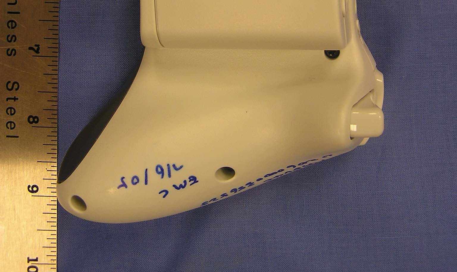
Click to zoom
Application Details
- Equipment Class
- DSS - Part 15 Spread Spectrum Transmitter
- Date of Grant
- Sep 12, 2005
- Application Purpose
- Original Equipment
- Date of Application
- Sep 12, 2005
- Equipment Note
- Frequency Hopping Wireless Controller
- Frequency Range
- 2402.00000000 - 2482.00000000
- Company
- Microsoft Corporation
- Country
- United States
Documents & Files
Document Text
Text extracted from the exhibit documents filed with the FCC. Open a document above to read the original.
Users Manual
Xbox 360 Wireless Controller Thanks for choosing the Xbox 360 Wireless Controller. Your wireless controller lets you experience the ultimate in wireless freedom with the same precision, speed, and accuracy as a wired controller. The Xbox 360 Wireless Controller features: • 2.4-GHz wireless technology with nine-meter range. • Integrated headset port. • Adjustable vibration feedback for longer battery life. The Xbox 360 Wireless Controller is for use exclusively with the Xbox 360™ video game and entertainment system. For information about using the Xbox 360 Wireless Controller with a particular game, see your game manual. To enhance your experience with the wireless controller, try the Xbox 360 Rechargeable Battery Pack and the Xbox 360 Play & Charge Kit. If you're looking to expand your wireless experience, consider the Xbox 360 Universal Media Remote and the Xbox 360 Wireless Networking Adapter. Before using this product, read this manual and the Xbox 360 console manuals for important safety and health information. Keep all manuals for future reference. For replacement manuals, go to www.xbox.com/support or call Xbox Customer Support (see ”If You Need More Help”). The limited warranty covering this product is contained in the Xbox 360 Warranty manual (Volume 2). Dispose of this product in accordance with local and national disposal regulations (if any), including those governing the recovery and recycling of waste electrical and electronic equipment (WEEE). Disposable Battery Safety Improper use of batteries may result in battery fluid leakage, heating, or explosion. Released battery fluid is corrosive and may be toxic. It can cause skin and eye burns, and is harmful if swallowed. To reduce the risk of injury: • Keep batteries out of reach of children. • Do not heat, open, puncture, mutilate, or dispose of batteries in fire. • Do not mix new and old batteries or batteries of different types (for example, carbon-zinc and alkaline batteries). • Remove batteries if they are worn out or before storing for an extended period of time. Do not leave batteries in the AA battery holder when it is not installed in the controller. • If a battery leaks, remove all batteries, taking care to keep the leaked fluid from touching your skin or clothes. If fluid from the battery comes into contact with skin or clothes, flush skin with water immediately. Before inserting new batteries, thoroughly clean the battery compartment with a damp paper towel, or follow the battery manufacturer's recommendations for cleanup. • Dispose of old, depleted, or leaking batteries in accordance with the battery manufacturer’s instructions and Local and National Disposal Regulations. Set Up Your Xbox 360 Wireless Controller Before you can use your Xbox 360 Wireless Controller with your Xbox 360 console, you need to: 1. Insert a battery pack. The wireless controller uses only the AA battery pack (provided) with AA disposable batteries or the Microsoft Xbox 360 Rechargeable Battery Pack (sold separately). 2. Introduce the controller to the console by wirelessly connecting the two. Insert Batteries To insert batteries into the wireless controller AA battery pack: 1. Press the tab on the top of the AA battery pack and pull down to detach it from the controller. 2. Insert two new AA (LR6) batteries with their positive (+) and negative (–) ends positioned as shown on the underside of the battery pack. For best performance, AA rechargeable batteries are not recommended. 3. Slide the AA battery pack back into place on the controller and push in to lock. Remove Controller Batteries Aboard Aircraft Before boarding any aircraft or packing the wireless controller in luggage that will be checked, remove any batteries from the wireless controller. The wireless controller can transmit radio frequency (RF) energy, much like a cellular telephone, whenever batteries are installed. Connect Your Controller Up to four controllers, wired and wireless, can be actively connected to a console at one time. Each connected controller gets a quadrant on the Ring of Light. Before you can connect a wireless controller, at least one quadrant must be free (unlit). To disconnect a wireless controller, press and hold the wireless controller Xbox Guide button for three seconds, and then turn it off. For a wired controller, disconnect the cable connector. To connect your wireless controller to your console: 1. Press and hold down the Xbox Guide button until the controller powers on. 2. If your console is not on, press the power button to turn on the console. 3. Press and release the connect button on the console. 4. Press and release the connect button on the controller. 5. After the Ring of Light on the controller and console spin and flash once, the controller is connected. The quadrant that remains lit indicates the controller's position. Turn Your Console and Controller On To turn your console and controller on, press the Xbox Guide button on your controller. To turn on your console only, press the power button on your console. To turn on your controller only, press the Start button on your controller. Turn Your Console and Controller Off To turn your console and controller off, press and hold the Xbox Guide button on your controller for three seconds. Then select whether you want to turn off just your controller or both your controller and your console. (Selecting the console will turn off both the console and all connected controllers.) To turn off your console only, press the power button on your console. NOTE • When you turn off your console, your controller will still be connected the next time you turn it on. • Your controller is connected to only one console at a time. You can connect to a new console at any time, but your connection to the previously connected console will be lost. • The Xbox 360 Wireless Controller works only within 30 feet (nine meters) of the console. Objects between the controller and the console can reduce this range. Using Your …
Text truncated - open the document above for the full version.
Cover Letter(s)
1 Helen Zhao Subject:FW: Microsoft Corporation, FCC ID: C3K-WKS368, Assessment NO.: AN05T5074, Notice#1 Revised RadonArgonTheoryofOp.p... 05U3587-1 FCC FHSS Report Rev.... Radon Antenna Specification.pd... Question #1: The test report section 5.2: Where does -1.80dBm come from? It does not match section 7.1.5 Maximum Output Power measurement. CCS : Attached please find revised test report. Question #2: The test report section 5.6 configuration #1: Please clarify what is the EUT. The EUT should be game controller instead of the Console. Also please indicate clearly what "3 Wireless Game Controller w/Headphones" were attached with and why there are only 3 game controllers connected during the test, while Theory of Operation indicates the wireless system XBox 360 can support operation of 4 simultaneous game controller. CCS : Section 5.6 of test report has been revised. Based upon the preliminary tests, adding of additional game controllers have no impact on the radiated emission. Radiated emission data were reported with 3 game controllers. Question #3: The test report section 5.6 configuration #2: Please clarify what is the EUT. The EUT should be game controller instead of the Console. Also please provide I/O cable list for configuration #2. CCS : Section 5.6 of test report has been revised. Attached please find revised test report. Question #4: The test report page 11, 22, 29 & 30: Please check frequencies of middle and high channels, they do not agree with other sections. CCS : Please refer to revised test report. Question #5: The test report section 7.1.4 "MANUFACTURERS DECLARATION": indicates "There are 5 frequencies used in every 8 mS frame of the protocol, for an average hopping rate of about 750 hops/sec", which appears incorrect. Please verify. CCS :Theory of operation and Section 7.1.4 manufacturers declaration on the average time of occupancies have been revised with more detailed protocol explanation. Please refer to attached revised test report and revised theory of operation. Question #6: This is a hand-held device. Please confirm whether the device was tested in three orthogonal planes. CCS : The highest emission level is generated when the controller is positioned at x axes. Statement to comply with section 13.1.4.1 of ANSI C63.4:2003 is added to section 7.4 of test report. 2 Question #7: The Theory of Operation exhibit in the filing does not provide enough information to justify compliance of "AVERAGE TIME OF OCCUPANCY". The MANUFACTURERS DECLARATION in the test report lists data only, it's not clear what these data are derived from. From theory or experiment? Please resubmit Theory of Operation to provide more detailed information. CCS :Due to Propitiatory communication protocol used on this device, the average time of occupancy is based upon the theory. The manufacturer declaration has been revised in the section 7.1.4 and theory of operation has been updated. Question #8: Theory of Operation indicates the antenna gain for gamepad is less than 2dBi, the test report indicates 3.6dBi. Please explain. CCS : The gain indicated in the theory of operation is based the normal gain. 3.6 dBi antenna gain listed in the test report is based upon the antenna specification. Attached please find the antenna specification.
ID Label/Location Info
� X804645-001 PART NUMBER SCALE 1:1 SOFTWARE / VERSION Illustrator CS DESCRIPTION LABEL,WIRELESS CNTR,PRODUCT ID,NA DRAWN BY / DATE Lawrence / 07.22.05 ARTWORK NUMBER COLOR SPECIFICATIONS PMS7541 with Med Fussion PROPRIETARY NOTE THE INFORMATION CONTAINED HEREON IS CONFIDENTIAL, IS SUBMITTED IN CONFIDENCE,AND IS PROPRIETAR Y INFORMATION OF MICROSOFT CORPORA- TION,AND SHALL ONL Y BE USED IN THE FURTHERANCE OF, THE CONTRACT OF WHICHTHIS DRAWING FORMS A PART, AND SHALL NOT, WITHOUT MICROSOFT CORPORATION ÕS PRIOR WRITTEN APPROVAL, BE REPRODUCED OR IN ANY WAY USED IN WHOLE OR IN PAR T IN CONNECTION WITH SERVICES OR EQUIPMENT HEREON MA Y NOT BE DISCLOSED TOA THIRD PARTY WITHOUT CONSENT OF MICROSOFT CORPORATION,ANDTHEN, ONL Y PURSUANTTOA MICROSOFT APPROVED NONDISCLOSURE AGREEMENT . AW804645-001.aiB REVISION MADE IN CHINA XBOX360 WIRELESS CONTROLLER MICROSOFT CORPORATION LISTED ITE ACCESSORY 27FC For use with XBOX360 Console See User’s manual for More Information 5V 450mA 004NYCA0272 FCC ID:C3K-WKS368 IC: 3048A-WKS368 = Medium Fusion Gray = PMS 7541 C = Die line
Parts List/Tune Up Info
Date: 05-Nov-2004 Radon antenna, narrowed Technical Documentation File: RadonV2PifaEval02-narrowed.doc Ref.: TJG Page: 1 of 3 This document and the information contained is property of RTX Telecom A/S, Denmark, and should be regarded as confidential. Unauthorized copying is not allowed. The information in this document is believed to be correct at the time of writing. RTX Telecom A/S reserves the right at any time to change said content, circuitry and specifications. Narrowing Radon Antenna The Radon antenna has been narrowed due to mechanical constraints. A test was made, where the entire antenna was cut to 3.5mm width, by cutting on the front side of the antenna only. The test was quite successful, and the antenna was easy to match using a 2.2pF series capacitor. Antenna length from bend is 21.5mm, and the antenna is still raised about 2 mm. Included are measurements of return loss and gain of the antenna. CH1 S 22 log MAG10 dB/REF 0 dB START 2 000.000 000 MHzSTOP 3 000.000 000 MHz Cor Del PRm MARKER 1 2.4 GHz 5 Nov 2004 09:36:42 1 2 1_:-23.38 dB 2 400.000 000 MHz 2_:-16.098 dB 2.48 GHz Figure 1: Return loss of narrower Radon antenna. Date: 05-Nov-2004 Radon antenna, narrowed Technical Documentation File: RadonV2PifaEval02-narrowed.doc Ref.: TJG Page: 2 of 3 This document and the information contained is property of RTX Telecom A/S, Denmark, and should be regarded as confidential. Unauthorized copying is not allowed. The information in this document is believed to be correct at the time of writing. RTX Telecom A/S reserves the right at any time to change said content, circuitry and specifications. Vertical gfedcb Horizontal gfedcb Sum gfedcb Emitted power - User Comments : No Comments Antenna Gain - RFG Frequency : 2.4 GHz - RFG Level : 0 dBm 0º 340º 320º 300º 280º260º 240º 220º 200º 180º 160º 140º 120º 100º80º 60º 40º 20º 3 2 1 0 -1 -2 -3 -4 -5 -6 -7 -8 -9 -10 -11 -12 -13 -14 3 2 1 0 -1 -2 -3 -4 -5 -6 -7 -8 -9 -10 -11 -12 -13 -14 Figure 2: Horizontal radiation pattern. 0° is towards user. Date: 05-Nov-2004 Radon antenna, narrowed Technical Documentation File: RadonV2PifaEval02-narrowed.doc Ref.: TJG Page: 3 of 3 This document and the information contained is property of RTX Telecom A/S, Denmark, and should be regarded as confidential. Unauthorized copying is not allowed. The information in this document is believed to be correct at the time of writing. RTX Telecom A/S reserves the right at any time to change said content, circuitry and specifications. Vertical gfedcb Horizontal gfedcb Sum gfedcb Emitted power - User Comments : No Comments Antenna Gain - RFG Frequency : 2.4 GHz - RFG Level : 0 dBm 0º 340º 320º 300º 280º260º 240º 220º 200º 180º 160º 140º 120º 100º80º 60º 40º 20º 4 2 0 -2 -4 -6 -8 -10 -12 -14 -16 -18 -20 4 2 0 -2 -4 -6 -8 -10 -12 -14 -16 -18 -20 Figure 3: Vertical radiation pattern. 0° is towards battery compartment.
Test Report
FCC CFR47 PART 15 SUBPART C CERTIFICATION TEST REPORT FOR FREQUENCY HOPPING WIRELESS CONTROLLER MODEL NUMBER: XBOX 360 WIRELESS CONTROLLER FCC ID: C3K-WKS368 REPORT NUMBER: 05U3587-1B ISSUE DATE: AUGUST 25, 2005 Prepared for MICROSOFT CORPORATION ONE MICROSOFT WAY REDMOND, WA 98052-3699 U.S.A. Prepared by COMPLIANCE ENGINEERING SERVICES, INC. d.b.a. COMPLIANCE CERTIFICATION SERVICES 561F MONTEREY ROAD, MORGAN HILL, CA 95037, USA TEL: (408) 463-0885 FAX: (408) 463-0888 REPORT NO: 05U3587-1B DATE: AUGUST 25, 2005 EUT: WIRELESS CONTROLLER FCC ID: C3K-WKS368 Page 2 of 70 COMPLIANCE CERTIFICATION SERVICES DOCUMENT NO: CCSUP4031A 561F MONTEREY ROAD, MORGAN HILL, CA 95037 USA TEL: (408) 463-0885 FAX: (408) 463-0888 This report shall not be reproduced except in full, without the written approval of CCS. Revision History Rev. Issue Date Revisions Revised By A Initial Issue A.1 8-11-05 Added manufacturers Avg time of occupancy statement, deleted occupancy plots in lieu of statement. DG B 8-24-05 Update max output power table, modified setup diagrams for proper EUT, added configuration 2 I/O cable table, updated tables to show correct frequencies tested. DG 8-25-05 Update max output power table D.Z. Update section 7.1.4 to declare that there is only minimum of 15 channels and update the timing to describe the average time of occupancy requirement REPORT NO: 05U3587-1B DATE: AUGUST 25, 2005 EUT: WIRELESS CONTROLLER FCC ID: C3K-WKS368 Page 3 of 70 COMPLIANCE CERTIFICATION SERVICES DOCUMENT NO: CCSUP4031A 561F MONTEREY ROAD, MORGAN HILL, CA 95037 USA TEL: (408) 463-0885 FAX: (408) 463-0888 This report shall not be reproduced except in full, without the written approval of CCS. TABLE OF CONTENTS 1. ATTESTATION OF TEST RESULTS............................................................................................. 4 2. TEST METHODOLOGY .................................................................................................................. 5 3. FACILITIES AND ACCREDITATION .......................................................................................... 5 4. CALIBRATION AND UNCERTAINTY.......................................................................................... 5 4.1. MEASURING INSTRUMENT CALIBRATION ............................................................................. 5 4.2. MEASUREMENT UNCERTAINTY ............................................................................................... 5 5. EQUIPMENT UNDER TEST............................................................................................................6 5.1. DESCRIPTION OF EUT ..............................................................................................................6 5.2. MAXIMUM OUTPUT POWER .................................................................................................... 6 5.3. DESCRIPTION OF AVAILABLE ANTENNAS ............................................................................. 6 5.4. SOFTWARE AND FIRMWARE .................................................................................................... 6 5.5. WORST-CASE CONFIGURATION AND MODE......................................................................... 6 6. TEST AND MEASUREMENT EQUIPMENT .............................................................................. 11 7. LIMITS AND RESULTS ................................................................................................................. 12 7.1. ANTENNA PORT CHANNEL TESTS ......................................................................................... 12 7.1.1. 20 dB BANDWIDTH ......................................................................................................... 12 7.1.2. HOPPING FREQUENCY SEPARATION......................................................................... 16 7.1.3. NUMBER OF HOPPING CHANNELS ............................................................................. 18 7.1.4. AVERAGE TIME OF OCCUPANCY ............................................................................... 22 7.1.5. PEAK OUTPUT POWER .................................................................................................. 23 7.1.6. MAXIMUM PERMISSIBLE EXPOSURE ........................................................................ 27 7.1.7. AVERAGE POWER........................................................................................................... 30 7.1.8. PEAK POWER SPECTRAL DENSITY ............................................................................ 31 7.1.9. CONDUCTED SPURIOUS EMISSIONS.......................................................................... 35 7.2. RADIATED EMISSIONS.............................................................................................................44 7.2.1. TRANSMITTER RADIATED SPURIOUS EMISSIONS ................................................. 44 7.2.2. TRANSMITTER RADIATED EMISSIONS ABOVE 1 GHZ .......................................... 47 7.2.3. WORST-CASE RADIATED EMISSIONS BELOW 1 GHz ............................................. 58 7.3. POWERLINE CONDUCTED EMISSIONS ................................................................................ 62 8. SETUP PHOTOS .............................................................................................................................. 66 REPORT NO: 05U3587-1B DATE: AUGUST 25, 2005 EUT: WIRELESS CONTROLLER FCC ID: C3K-WKS368 Page 4 of 70 COMPLIANCE CERTIFICATION SERVICES DOCUMENT NO: CCSUP4031A 561F MONTEREY ROAD, MORGAN HILL, CA 95037 USA TEL: (408) 463-0885 FAX: (408) 463-0888 This report shall not be reproduced except in full, without the written approval of CCS. 1. ATTESTATION OF TEST RESULTS COMPANY NAME: MICROSOFT CORPORATION ONE MICROSOFT WAY REDMOND, WA 98052-6399 EUT DESCRIPTION: FREQUENCY HOPPING WIRELESS CONTROLLER MODEL: XBOX 360 WIRELESS CONTROLLER SERIAL NUMBER: 236525, 906525, 356525, 4342517 DATE TESTED: JULY 8 - JULY 23, 2005 APPLICABLE…
Text truncated - open the document above for the full version.
Test Setup Photos
REPORT NO: 05U3587-1 DATE: JULY 25, 2005 EUT: WIRELESS CONTROLLER FCC ID: C3K-WKS368 Page 65 of 69 COMPLIANCE CERTIFICATION SERVICES DOCUMENT NO: CCSUP4031A 561F MONTEREY ROAD, MORGAN HILL, CA 95037 USA TEL: (408) 463-0885 FAX: (408) 463-0888 This report shall not be reproduced except in full, without the written approval of CCS. 8. SETUP PHOTOS ANTENNA PORT CONDUCTED RF MEASUREMENT SETUP ANTENNA PORT CONDUCTED PHOTO REPORT NO: 05U3587-1 DATE: JULY 25, 2005 EUT: WIRELESS CONTROLLER FCC ID: C3K-WKS368 Page 66 of 69 COMPLIANCE CERTIFICATION SERVICES DOCUMENT NO: CCSUP4031A 561F MONTEREY ROAD, MORGAN HILL, CA 95037 USA TEL: (408) 463-0885 FAX: (408) 463-0888 This report shall not be reproduced except in full, without the written approval of CCS. RADIATED RF MEASUREMENT SETUP RADIATED FRONT PHOTO REPORT NO: 05U3587-1 DATE: JULY 25, 2005 EUT: WIRELESS CONTROLLER FCC ID: C3K-WKS368 Page 67 of 69 COMPLIANCE CERTIFICATION SERVICES DOCUMENT NO: CCSUP4031A 561F MONTEREY ROAD, MORGAN HILL, CA 95037 USA TEL: (408) 463-0885 FAX: (408) 463-0888 This report shall not be reproduced except in full, without the written approval of CCS. RADIATED BACK PHOTO REPORT NO: 05U3587-1 DATE: JULY 25, 2005 EUT: WIRELESS CONTROLLER FCC ID: C3K-WKS368 Page 68 of 69 COMPLIANCE CERTIFICATION SERVICES DOCUMENT NO: CCSUP4031A 561F MONTEREY ROAD, MORGAN HILL, CA 95037 USA TEL: (408) 463-0885 FAX: (408) 463-0888 This report shall not be reproduced except in full, without the written approval of CCS. POWERLINE CONDUCTED EMISSIONS MEASUREMENT SETUP LINE CONDUCTED FRONT PHOTO REPORT NO: 05U3587-1 DATE: JULY 25, 2005 EUT: WIRELESS CONTROLLER FCC ID: C3K-WKS368 Page 69 of 69 COMPLIANCE CERTIFICATION SERVICES DOCUMENT NO: CCSUP4031A 561F MONTEREY ROAD, MORGAN HILL, CA 95037 USA TEL: (408) 463-0885 FAX: (408) 463-0888 This report shall not be reproduced except in full, without the written approval of CCS. END OF REPORT LINE CONDUCTED BACK PHOTO
Contact Information
Applicant
Hasnain Syed(SR. DIR EMC/SI&RF COMPLIANCE)
Test Firm
Compliance Certification Services IncSteve Cheng
Technical Specifications
| # | Rule Parts | Frequency Range | Power Output |
|---|---|---|---|
| 1 | 15C | 2.40 GHz - 2.48 GHz | 1.95 mW |
Other Applications from Microsoft Corporation
C3K2147
Aug 28, 2026Wireless input device
Equipment Class
DTS - Digital Transmission SystemC3K2148
Aug 12, 2026Portable Computing Device
Equipment Class
DXX - Part 15 Low Power Communication Device TransmitterC3K2149
Aug 12, 2026Portable Computing Device
Equipment Class
DXX - Part 15 Low Power Communication Device TransmitterC3K2152
Aug 11, 2026Wireless Accessory
Equipment Class
DTS - Digital Transmission SystemC3K2150
Aug 06, 2026Portable Computing Device
Equipment Class
DXX - Part 15 Low Power Communication Device Transmitter