C3K1399802.11 b/g/n WLAN Client Module
Microsoft Corporation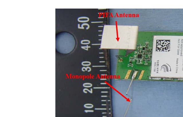
Click to zoom
Application Details
- Equipment Class
- DTS - Digital Transmission System
- Date of Grant
- Apr 07, 2011
- Application Purpose
- Original Equipment
- Date of Application
- Mar 14, 2011
- Equipment Note
- 802.11 b/g/n WLAN Client Module
- Frequency Range
- 2422.00000000 - 2452.00000000
- Company
- Microsoft Corporation
- Country
- United States
Documents & Files
Document Text
Text extracted from the exhibit documents filed with the FCC. Open a document above to read the original.
Users Manual
Microsoft Corp. Model 1399 installation instructions End Product Labelling The Final end product label must contain the following statement on the product label: “This Device Contains FCC ID: C3K1399” Notes for OEM Integrators This device is for use only in the Xbox console system for which it was designed, and installed during the console manufacturing process. The antenna must be installed such that 20 cm is maintained between the antenna and users. The transmitter module may not be co-located with any other transmitter or antenna. The transmitter module is approved using the FCC “unlicensed modular transmitter” approval method, therefore the module must only be used with the originally approved antennas. The end user should NOT be provided any instructions on how to remove or install the device. User Manual Statements The end product user manual must contain the following statements; "IMPORTANT NOTE: To comply with FCC RF exposure compliance requirements, the antenna used for this transmitter must be installed to provide a separation distance of at least 20 cm from all persons and must not be co-located or operating in conjunction with any other antenna or transmitter." A statement to caution the user that changes or modifications not expressly appproved by Microsoft could void the user’s authority to operate the equipment. (reference FCC Title 47 Section 15.21) “This equipment has been tested and found to comply with the limits for a Class B digital device, pursuant to Part 15 of the FCC rules. These limits are designed to provide reasonable protection against harmful interference in a residential installation. This equipment generates, uses, and can radiate radio frequency energy and, if not installed and used in accordance with the instructions, may cause harmful interference to radio communications. However, there is no guarantee that interference will not occur in a particular installation. If this equipment does cause harmful interference to radio or television reception, which can be determined by turning the equipment off and on, the user is encouraged to try to correct the interference by one or more of the following measures: • Reorient or relocate the receiving antenna. • Increase the separation between the equipment and receiver. • Connect the equipment into an outlet on a circuit different from that to which the receiver is connected. • Consult the dealer or an experienced radio/TV technician for help.” (reference FCC Title 47 Section 15.105)
Cover Letter(s)
Microsoft Corporation FCC ID: C3K1399 Request for transmitter modular approval Transmitter Module Characteristics Item Requirements EUT 1 The module has its own RF shielding Device is equipped with Metal shielding to cover RF section. Refer to external photos 2 All modulation and data input(s) are buffered. All inputs to the modules are buffered through Atheros AR9271. 3 The module has its own power supply regulation and local reference oscillator. Internal 1.2V power regulator. 40 MHz crystal provides reference frequency to AR9271 to generate LO frequencies. 4 Comply with antenna requirements of Section 15.203 and 15.204(c) Antennas are permanently connected and non replaceable by the user. 5 The host device, as a stand-alone unit without any separately certified modules, complies with all applicable Radio Standards Specifications. Device was tested standalone with Laptop as support device. See setup photographs 6 The host device complies with the certification labeling requirements of each of the modules it contains. Refer to label format exhibit. 7 The modular transmitter is manufactured so that the user cannot influence the operation of the transmitter that will operate outside of the scope of the regulations. There are no adjustments or user accessible controls in hardware or software that will influence operation of the transmitter. 8 Address compliance with the Commission’s RF exposure limits in Sections 1.1310 and 2.1093. In addition, spread spectrum transmitters operating under section 15.247 are required to address RF exposure compliance in accordance with Section 15.247(b)(4) Refer to radio frequency exposure calculation exhibit.
ID Label/Location Info
Label content for Model 1399 Microsoft Corporation Model 1399 FCC ID: C3K1399 IC: 3048A-1399
ID Label/Location Info
Microsoft Corporation Model 1399 FCC label location Top Side PCB
RF Exposure Info
Compliance Certification Services Inc. Report No.: T100816101 FCC ID: C3K1399 IC: 3048A-1399 Date of Issue: October 27, 2010 Page 118 Rev. 00 APPENDIX I RADIO FREQUENCY EXPOSURE LIMIT According to §15.247(i), systems operating under the provisions of this section shall be operated in a manner that ensures that the public is not exposed to radio frequency energy levels in excess of the Commission's guidelines. See § 1.1307(b)(1) of this chapter. EUT Specification EUT 802.11 b/g/n WLAN Client Frequency band (Operating) WLAN: 2.412GHz ~ 2.462GHz WLAN: 5.18GHz ~ 5.32GHz / 5.50GHz ~ 5.70GHz WLAN: 5.745GHz ~ 5.825GHz Others Device category Portable (<20cm separation) Mobile (>20cm separation) Others Exposure classification Occupational/Controlled exposure (S = 5mW/cm 2 ) General Population/Uncontrolled exposure (S=1mW/cm 2 ) Antenna diversity Single antenna Multiple antennas Tx diversity Rx diversity Tx/Rx diversity Max. output power IEEE 802.11b mode: 19.36 dBm (86.29 mW) IEEE 802.11g mode: 25.12 dBm (325.08 mW) draft 802.11n Standard-20 MHz Channel mode: 25.09 dBm (322.84 mW) draft 802.11n Wide-40 MHz Channel mode: 21.16 dBm (130.61 mW) Antenna gain (Max) 3 dBi (Numeric gain: 1.99) Evaluation applied MPE Evaluation* SAR Evaluation N/A Remark: 1. The maximum output power is 25.12dBm (325.08mW) at 2437MHz (with 1.99 numeric antenna gain.) 2. DTS device is not subject to routine RF evaluation; MPE estimate is used to justify the compliance. 3. For mobile or fixed location transmitters, no SAR consideration applied. The maximum power density is 1.0 mW/cm2 even if the calculation indicates that the power density would be larger. TEST RESULTS No non-compliance noted. Compliance Certification Services Inc. Report No.: T100816101 FCC ID: C3K1399 IC: 3048A-1399 Date of Issue: October 27, 2010 Page 119 Rev. 00 Calculation Given d GP E ×× = 30 & 3770 2 E S= Where E = Field strength in Volts / meter P = Power in Watts G = Numeric antenna gain d = Distance in meters S = Power density in milliwatts / square centimeter Combining equations and re-arranging the terms to express the distance as a function of the remaining variables yields: 2 3770 30 d GP S ×× = Changing to units of mW and cm, using: P (mW) = P (W) / 1000 and d (cm) = d(m) / 100 Yields () () 2 2 0796.0 100/3770 1000/30 d GP d GP S × ×= × ×× = Equation 1 Where d = Distance in cm P = Power in mW G = Numeric antenna gain S = Power density in mW / cm 2 Maximum Permissible Exposure Substituting the MPE safe distance using d = 20 cm into Equation 1: Yields GPS××=000199.0 Where P = Power in mW G = Numeric antenna gain S = Power density in mW / cm 2 Compliance Certification Services Inc. Report No.: T100816101 FCC ID: C3K1399 IC: 3048A-1399 Date of Issue: October 27, 2010 Page 120 Rev. 00 IEEE 802.11b mode: EUT output power = 86.29 mW Numeric Antenna gain = 1.99 Æ Power density =0.034172 mW / cm2 IEEE 802.11g mode: EUT output power = 325.08 mW Numeric Antenna gain = 1.99 Æ Power density = 0.128735 mW / cm2 draft 802.11n Standard-20 MHz Channel mode: EUT output power = 322.84 mW Numeric Antenna gain = 1.99 Æ Power density = 0.127848 mW / cm2 draft 802.11n Wide-40 MHz Channel mode: EUT output power = 130.61 mW Numeric Antenna gain = 1.99 Æ Power density = 0.051723 mW / cm2 (For mobile or fixed location transmitters, the maximum power density is 1.0 mW/cm 2 even if the calculation indicates that the power density would be larger.)
Test Report
Compliance Certification Services Inc. Report No.: T100816101 FCC ID: C3K1399 IC: 3048A-1399 Date of Issue: October 27, 2010 Note: This report shall not be reproduced except in full, without the written approval of Compliance Certification Services Inc. This document may be altered or revised by Compliance Certification Services Inc. personnel only, and shall be noted in the revision section of the document. Page 1 Total Page: 125 Rev. 00 FCC 47 CFR PART 15 SUBPART C & INDUSTRY CANADA RSS-210 TEST REPORT For 802.11 b/g/n WLAN Client Model: 1399 Trade Name: Microsoft Issued to Microsoft Corporation One Microsoft Way, Redmond, WA 98052 Issued by Compliance Certification Services Inc. No. 11, Wu-Gong 6 th Rd., Wugu Industrial Park, Taipei Hsien 248, Taiwan (R.O.C.) http://www.ccsrf.com [email protected] Compliance Certification Services Inc. Report No.: T100816101 FCC ID: C3K1399 IC: 3048A-1399 Date of Issue: October 27, 2010 Page 2 Rev. 00 TABLE OF CONTENTS 1. TEST RESULT CERTIFICATION....................................................................................................3 2. EUT DESCRIPTION ...........................................................................................................................4 3. TEST METHODOLOGY ....................................................................................................................5 3.1 EUT CONFIGURATION........................................................................................................................5 3.2 EUT EXERCISE....................................................................................................................................5 3.3 GENERAL TEST PROCEDURES.............................................................................................................5 3.4 FCC PART 15.205 RESTRICTED BANDS OF OPERATIONS ........................................................6 3.5 DESCRIPTION OF TEST MODES...........................................................................................................7 4. INSTRUMENT CALIBRATION........................................................................................................8 4.1 MEASURING INSTRUMENT CALIBRATION......................................................................................8 4.2 MEASUREMENT EQUIPMENT USED .........................................................................................8 4.3 MEASUREMENT UNCERTAINTY ...............................................................................................9 5. FACILITIES AND ACCREDITATIONS ........................................................................................10 5.1 FACILITIES .......................................................................................................................................10 5.2 EQUIPMENT......................................................................................................................................10 5.3 LABORATORY ACCREDITATIONS AND LISTING................................................................................10 5.4 TABLE OF ACCREDITATIONS AND LISTINGS.....................................................................................11 6. SETUP OF EQUIPMENT UNDER TEST .......................................................................................12 6.1 SETUP CONFIGURATION OF EUT.......................................................................................................12 6.2 SUPPORT EQUIPMENT ...............................................................................................................12 7. APPLICABLE RULES FOR INDUSTRY CANADA RSS-210 .....................................................13 8. FCC PART 15.247 REQUIREMENTS & RSS-210 REQUIREMENTS....................................19 8.1 99% BANDWIDTH............................................................................................................................19 8.2 6DB BANDWIDTH.............................................................................................................................27 8.3 PEAK POWER....................................................................................................................................35 8.4 BAND EDGES MEASUREMENT ................................................................................................37 8.5 PEAK POWER SPECTRAL DENSITY....................................................................................................70 8.6 SPURIOUS EMISSIONS.................................................................................................................78 8.7 RADIATED EMISSIONS ..............................................................................................................85 8.8 POWERLINE CONDUCTED EMISSIONS.............................................................................................115 APPENDIX I RADIO FREQUENCY EXPOSURE .............................................................................118 APPENDIX II PHOTOGRAPHS OF TEST SETUP ...........................................................................121 APPENDIX 1 - PHOTOGRAPHS OF EUT Compliance Certification Services Inc. Report No.: T100816101 FCC ID: C3K1399 IC: 3048A-1399 Date of Issue: October 27, 2010 Page 3 Rev. 00 1. TEST RESULT CERTIFICATION Applicant: Microsoft Corporation One Microsoft Way, Redmond, WA 98052 Manufacturer: Atheros Communications 5480 Great America Parkway, Santa Clara, CA 95054 Equipment Under Test: 802.11 b/g/n WLAN Client Trade Name: Microsoft Model: 1399 Date of Test: August 20 ~ October 7, 2010 APPLICABLE STANDARDS STANDARD TEST RESULT FCC 47 CFR Part 15 Subpart C & Industry Canada RSS-210 Issue 7 June, 2007 No non-compliance noted We hereby certify that: The above equipment was tested by Compliance Certification Services Inc. The test data, data evaluation, test procedures, and equipment configurations shown in this report were made in a…
Text truncated - open the document above for the full version.
Test Setup Photos
Compliance Certification Services Inc. Report No.: T100816101 FCC ID: C3K1399 IC: 3048A-1399 Date of Issue: October 27, 2010 Page 121 Rev. 00 APPENDIX II PHOTOGRAPHS OF TEST SETUP Conducted Emissions Setup Photos Compliance Certification Services Inc. Report No.: T100816101 FCC ID: C3K1399 IC: 3048A-1399 Date of Issue: October 27, 2010 Page 122 Rev. 00 Radiated Emissions Setup Photos For Monopole Antenna & PIFA Antenna X axis Front photo Compliance Certification Services Inc. Report No.: T100816101 FCC ID: C3K1399 IC: 3048A-1399 Date of Issue: October 27, 2010 Page 123 Rev. 00 Y axis Front photo Compliance Certification Services Inc. Report No.: T100816101 FCC ID: C3K1399 IC: 3048A-1399 Date of Issue: October 27, 2010 Page 124 Rev. 00 Z axis Front photo Compliance Certification Services Inc. Report No.: T100816101 FCC ID: C3K1399 IC: 3048A-1399 Date of Issue: October 27, 2010 Page 125 Rev. 00 Powerline Conducted Emissions Setup Photos
Contact Information
Applicant
Hasnain Syed(SR. DIR EMC/SI&RF COMPLIANCE)
Technical Contact
Microsoft CorporationStephen Stegner
[email protected]425 706 2697
One Microsoft Way · Redmond, Washington · United States
Non-Technical Contact
Microsoft CorporationMike Boucher
[email protected]425 703 4529
Test Firm
Compliance Certification Services Inc.Hank Lee
Technical Specifications
| # | Rule Parts | Frequency Range | Power Output |
|---|---|---|---|
| 2 | 15C | 2.42 GHz - 2.45 GHz | 131.00 mW |
Other Applications from Microsoft Corporation
C3K2147
Aug 28, 2026Wireless input device
Equipment Class
DTS - Digital Transmission SystemC3K2148
Aug 12, 2026Portable Computing Device
Equipment Class
DXX - Part 15 Low Power Communication Device TransmitterC3K2149
Aug 12, 2026Portable Computing Device
Equipment Class
DXX - Part 15 Low Power Communication Device TransmitterC3K2152
Aug 11, 2026Wireless Accessory
Equipment Class
DTS - Digital Transmission SystemC3K2150
Aug 06, 2026Portable Computing Device
Equipment Class
DXX - Part 15 Low Power Communication Device Transmitter