C3K1501802.11 b/g/n WLAN Client
Microsoft Corporation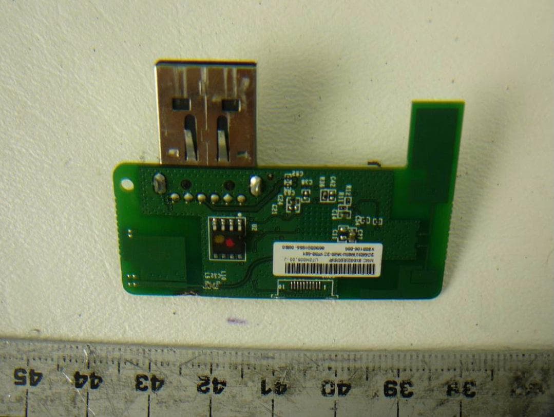
Click to zoom
Application Details
- Equipment Class
- DTS - Digital Transmission System
- Date of Grant
- Mar 18, 2012
- Application Purpose
- Original Equipment
- Date of Application
- Mar 12, 2012
- Equipment Note
- 802.11 b/g/n WLAN Client
- Frequency Range
- 2422.00000000 - 2452.00000000
- Company
- Microsoft Corporation
- Country
- United States
Documents & Files
Document Text
Text extracted from the exhibit documents filed with the FCC. Open a document above to read the original.
Users Manual
Model 1501 OEM Manual Page 1 of 2 Microsoft Corp. Model 1501 installation instructions End Product Labelling The Final end product label must contain the following statement on the product label: For United States & Canada “This Device Contains FCC ID: C3K1501” ”This Device Contains IC: 3048A-1501” For Taiwan Notes for OEM Integrators This device is for use only in the Xbox console system for which it was designed, and installed during the console manufacturing process. The antenna must be installed such that 20 cm is maintained between the antenna and users. The transmitter module may not be co- located with any other transmitter or antenna. The transmitter module is approved using the FCC “unlicensed modular transmitter” approval method, therefore the module must only be used with the originally approved antennas. The end user should NOT be provided any instructions on how to remove or install the device. User Manual Statements The end product user manual must contain the following statements; For customers in Singapore For customers in Taiwan 低功率電波輻性電機管理辦法 第十二條經型式認證合格之低功率射頻電機,非經許可,公司、商號或使 用者均不得擅自變更頻率、加大功率或變更原設計之特性及功能。 第十四條低功率射頻電機之使用不得影響飛航安全及干擾合法通信;經發 現有干擾現象時,應立即停用,並改善至無干擾時方得繼續使用。 前項合法通信,指依電信規定作業之無線電信。低功率射頻電機須忍受合法通信 或工業、科學及醫療用電波輻射性電機設備之干擾 消費者保護法第二十四條第二項:「輸入之商品或服務,應附中文標示及說明書,其內容不得較原產地之標示及說明書簡略 Model 1501 OEM Manual Page 2 of 2 For customers in Canada Cet appareil numérique de la classe B est conforme aux normes NMB-003, CNR-Gen, et CNR-210 du Canada. Son fonctionnement est assujetti aux deux conditions suivantes : (1) Cet appareil ne peut pas provoquer d’interférences nuisibles et (2) cet appareil doit accepter toute interférence reçue, y compris les interférences pouvant entraîner un fonctionnement non désiré. To comply with IC RF exposure compliance requirements, the antenna used for this transmitter must be installed to provide a separation distance of at least 20 cm from all persons and must not be co-located or operating in conjunction with any other antenna or transmitter. For Customers in the United States "IMPORTANT NOTE: To comply with FCC RF exposure compliance requirements, the antenna used for this transmitter must be installed to provide a separation distance of at least 20 cm from all persons and must not be co-located or operating in conjunction with any other antenna or transmitter." A statement to caution the user that changes or modifications not expressly appproved by Microsoft could void the user’s authority to operate the equipment. (reference FCC Section 15.21) “This device complies with Part 15 of the FCC Rules. Operation is subject to the following two conditions: (1) this device may not cause interference, and (2) this device must accept any interference received, including interference that may cause undesired operation.” (reference FCC Section 15.19(a)(3) ) “This equipment has been tested and found to comply with the limits for a Class B digital device, pursuant to Part 15 of the FCC rules. These limits are designed to provide reasonable protection against harmful interference in a residential installation. This equipment generates, uses, and can radiate radio frequency energy and, if not installed and used in accordance with the instructions, may cause harmful interference to radio communications. However, there is no guarantee that interference will not occur in a particular installation. If this equipment does cause harmful interference to radio or television reception, which can be determined by turning the equipment off and on, the user is encouraged to try to correct the interference by one or more of the following measures: • Reorient or relocate the receiving antenna. • Increase the separation between the equipment and receiver. • Connect the equipment into an outlet on a circuit different from that to which the receiver is connected. • Consult the dealer or an experienced radio/TV technician for help.” (reference FCC Title 47 Section 15.105)
Cover Letter(s)
Microsoft Corporation FCC ID: C3K1501 Request for transmitter modular approval Transmitter Module Characteristics Item Requirements EUT 1 The module has its own RF shielding Device is equipped with Metal shielding to cover RF section. Refer to external photos 2 All modulation and data input(s) are buffered. All inputs to the modules are buffered. 3 The module has its own power supply regulation and local reference oscillator. The device has internal 1.8V and 1.2V voltage regulators and a 40MHz local reference oscillator. 4 Comply with antenna requirements of Section 15.203 and 15.204(c) Antennas are non-replaceable by the user. 5 The host device, as a stand-alone unit without any separately certified modules, complies with all applicable Radio Standards Specifications. Device was tested standalone with Laptop as support device. See setup photographs 6 The host device complies with the certification labeling requirements of each of the modules it contains. Refer to label format exhibit. 7 The modular transmitter is manufactured so that the user cannot influence the operation of the transmitter that will operate outside of the scope of the regulations. There are no adjustments or user accessible controls in hardware or software that will influence operation of the transmitter. 8 Address compliance with the Commission’s RF exposure limits in Sections 1.1310 and 2.1093. In addition, spread spectrum transmitters operating under section 15.247 are required to address RF exposure compliance in accordance with Section 15.247(b)(4) Refer to radio frequency exposure calculation exhibit.
External Photos
Microsoft Corporation Model 1501 Photos
ID Label/Location Info
Microsoft Corporation Model 1501 Label Placement FCC Label Location
ID Label/Location Info
Microsoft Corporation Model 1501 Label Content Microsoft Corporation Model: 1501 FCC ID: C3K1501 IC: 3048A-1501
Internal Photos
Microsoft Corporation Model 1501 Internal Photo
Test Report
Note: This test report is prepared for the customer shown above and for the device described herein. It may not be duplicated or used in part without prior written consent from Bay Area Compliance Laboratories Corp. This report must not be used by the customer to claim product certification, approval, or endorsement by NVLAP*, NIST, or any agency of the Federal Government. * This report may contain data that are not covered by the NVLAP accreditation and are marked with an asterisk “*” (Rev.2) FCC PART 15 SUBPART C IC RSS-210, ISSUE 8, DECEMBER 2010 TEST AND MEASUREMENT REPORT For Microsoft Corporation One Microsoft Way Redmond, WA 98052, USA Report Type: Original Report Product Type: 802.11 b/g/n WiFi module Test Engineers: Jack Liu Quinn Jiang Report Number: R1109011-247 Rev C Report Date: 2012-03-02 Reviewed By: Victor Zhang EMC/RF Lead Prepared By: (84) Bay Area Compliance Laboratories Corp. 1274 Anvilwood Avenue, Sunnyvale, CA 94089, USA Tel: (408) 732-9162 Fax: (408) 732-9164 FCC ID: C3K1501 IC: 3048A-1501 Microsoft Corporation FCC ID: C3K1501, IC: 3048A-1501 Report Number: R1109011-247 Page 2 of 88 FCC Part 15C/IC RSS-210 Test Report TABLE OF CONTENTS 1 General Description .................................................................................................................................................... 5 1.1 Product Description for Equipment Under Test (EUT) ......................................................................................... 5 1.2 Mechanical Description of EUT ............................................................................................................................ 5 1.3 Objective ................................................................................................................................................................ 5 1.4 Related Submittal(s)/Grant(s) ................................................................................................................................ 5 1.5 Test Methodology .................................................................................................................................................. 5 1.6 Measurement Uncertainty ...................................................................................................................................... 5 1.7 Test Facility........................................................................................................................................................... 6 2 System Test Configuration ......................................................................................................................................... 7 2.1 Justification ............................................................................................................................................................ 7 2.2 EUT Exercise Software.......................................................................................................................................... 7 2.3 Special Equipment ................................................................................................................................................. 7 2.4 Equipment Modifications....................................................................................................................................... 7 2.5 Local Support Equipment ...................................................................................................................................... 7 2.6 Power Supply List and Details ............................................................................................................................... 8 2.7 EUT Internal Configuration Details ....................................................................................................................... 8 2.8 External I/O Cabling List and AC Cord................................................................................................................. 8 3 Summary of Test Results ............................................................................................................................................ 9 4 FCC §15.247 (i), §2.1091 & IC RSS-102 - RF Exposure .......................................................................................... 10 4.1 Applicable Standard ............................................................................................................................................. 10 4.2 MPE Prediction .................................................................................................................................................... 11 4.3 MPE Results......................................................................................................................................................... 11 5 FCC §15.203 & IC RSS-Gen §7.1.4 – Antenna Description .................................................................................... 12 5.1 Applicable Standard ............................................................................................................................................. 12 5.2 Antenna Connector Construction ......................................................................................................................... 12 6 FCC §15.207 & IC RSS-Gen 7.2.2- Conducted Emissions....................................................................................... 13 6.1 Applicable Standards ........................................................................................................................................... 13 6.2 Test Setup............................................................................................................................................................. 13 6.3 Test Equipment List and Details .......................................................................................................................... 13 6.4 Test Setup Block Diagram .................…
Text truncated - open the document above for the full version.
Test Setup Photos
Microsoft Corporation FCC ID: C3K1501, IC: 3048A-1501 Project Number: R1109011 Page 1 of 5 FCC & IC Test Setup Photos 1 Annex 2 – FCC & IC Test Setup Photographs 1.1 X-Axis setup 1.2 Y-Axis setup Microsoft Corporation FCC ID: C3K1501, IC: 3048A-1501 Project Number: R1109011 Page 2 of 5 Test Setup Photos 1.3 Z-Axis setup 1.4 Radiated Emission Front View @ 3 Meter Microsoft Corporation FCC ID: C3K1501, IC: 3048A-1501 Project Number: R1109011 Page 3 of 5 Test Setup Photos 1.5 Radiated Emission below 1GHz Rear View @ 3 Meter 1.6 Radiated Emission above 1 GHz Rear View @ 3 Meter Microsoft Corporation FCC ID: C3K1501, IC: 3048A-1501 Project Number: R1109011 Page 4 of 5 Test Setup Photos 1.7 AC Line Conducted Emission Front View 1.8 AC Line Conducted Emission Side View Microsoft Corporation FCC ID: C3K1501, IC: 3048A-1501 Project Number: R1109011 Page 5 of 5 Test Setup Photos 1.9 Bench Test - Front View --- END OF EXHIBIT ---
Contact Information
Applicant
Hasnain Syed(SR. DIR EMC/SI&RF COMPLIANCE)
Technical Contact
Microsoft CorporationStephen Stegner
One Microsoft Way · Redmond, Washington · United States
Non-Technical Contact
Microsoft CorporationJoy Algeria
Test Firm
Bay Area Compliance LaboratoryJohn Chan
Technical Specifications
| # | Rule Parts | Frequency Range | Power Output |
|---|---|---|---|
| 2 | 15C | 2.42 GHz - 2.45 GHz | 136.00 mW |
Other Applications from Microsoft Corporation
C3K2147
Aug 28, 2026Wireless input device
Equipment Class
DTS - Digital Transmission SystemC3K2148
Aug 12, 2026Portable Computing Device
Equipment Class
DXX - Part 15 Low Power Communication Device TransmitterC3K2149
Aug 12, 2026Portable Computing Device
Equipment Class
DXX - Part 15 Low Power Communication Device TransmitterC3K2152
Aug 11, 2026Wireless Accessory
Equipment Class
DTS - Digital Transmission SystemC3K2150
Aug 06, 2026Portable Computing Device
Equipment Class
DXX - Part 15 Low Power Communication Device Transmitter