C3K1525WLAN MODULE
Microsoft Corporation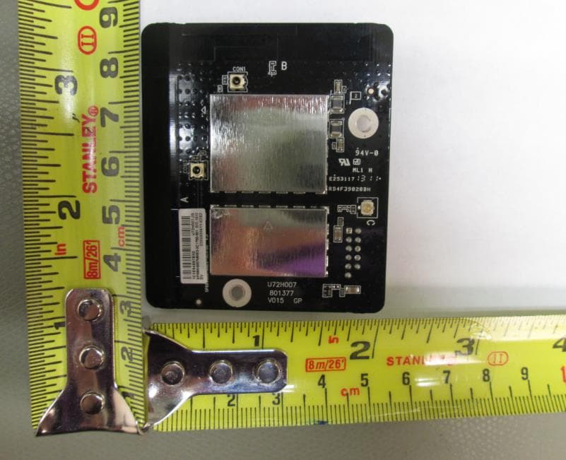
Click to zoom
Application Details
- Equipment Class
- NII - Unlicensed National Information Infrastructure TX
- Date of Grant
- Jun 18, 2013
- Application Purpose
- Original Equipment
- Date of Application
- Jun 11, 2013
- Equipment Note
- WLAN MODULE
- Frequency Range
- 5180.00000000 - 5240.00000000
- Company
- Microsoft Corporation
- Country
- United States
Documents & Files
Document Text
Text extracted from the exhibit documents filed with the FCC. Open a document above to read the original.
Users Manual
XBOX ONE AND KINECT SENSOR PRODUCT MANUAL IMPORTANT PRODUCT SAFETY AND WARRANTY INFORMATION This symbol identifies safety and health messages in this and other product manuals. Read this guide for important safety and health information for the product that you have purchased. WARNING: Failure to properly set up, use, and care for this product can increase the risk of serious injury, death, property damage, or damage to the product or related accessories. Read this manual and keep all printed guides for future reference. For replacement guides, go to xbox.com/xboxone/support/manual. USE AND CARE OF YOUR XBOX ONE CONSOLE WARNING: Do Not Attempt Repairs Do not attempt to take apart, open, service, or modify the product, accessories, or power supply. Doing so could present the risk of electric shock, fire or other hazard, or damage to your Xbox One. Any evidence of any attempt to open and/or modify this device, including any peeling, puncturing, or removal of any of the labels, will void the Limited Warranty and render the Xbox One ineligible for authorized repair. Modifying your console can result in a permanent ban from Xbox Live, which is required for game play and some other console uses. Usage and Cleaning Use in accordance with these instructions: Do not use near any heat sources. Only use attachments/accessories specified by Microsoft. Use alkaline (not rechargeable) batteries for best performance. Disconnect the console power supply from electrical power to prevent the console from being turned on and off or the disc tray from being ejected during cleaning. Clean the outside of the Xbox One only. Make sure that no objects are inserted into ventilation openings. Use a dry cloth—do not use abrasive pads, detergents, scouring powders, solvents (for example, alcohol, gasoline, paint thinner, or benzene), or other liquid or aerosol cleaners. Do not use compressed air. Do not use DVD head cleaner devices. Do not attempt to clean connectors. Clean the console feet and the surface on which the Xbox One rests with a dry cloth. Clean the surface on which the sensor rests with a dry cloth. Do not allow the console or sensor to become wet. To reduce the risk of fire or shock, do not expose the console or sensor to rain or other types of moisture. Avoid Smoke and Dust Do not use the console in smoky or dusty locations. Smoke and dust can damage the console, particularly the DVD drive. Disc Use Make sure the disc is held in place by the tabs on the disc tray so that it doesn’t fall out. To avoid jamming the disc drive and damaging discs or the console: Remove discs before moving the console or tilting it between the horizontal and vertical positions. Never use cracked discs. They can shatter inside the console and jam or break internal parts. When the console is vertical, do not use discs that are smaller than standard DVDs and CDs. Always return discs to their storage containers when they are not in the disc drive. Do not store discs in direct sunlight, near a heat source, or on your Xbox One. Always handle discs by their edges. To clean Xbox One game discs, DVDs or audio CDs: Hold discs by the edges; do not touch the disc surface with your fingers. Clean discs using a soft cloth, lightly wiping from the center outward. Do not use solvents; they can damage the disc. Do not use disc-cleaning devices. Metallic Objects and Stickers Do not place metallic items or stickers near or on the Xbox One, as they can interfere with controller, networking, and eject and power buttons. Adhesive Mounting Some devices use adhesive tape to mount components in your workspace. DO NOT mount on antiques, heirlooms, or other valuable or irreplaceable items. After mounting, removing the adhesive may damage the cosmetic coating and/or leave an adhesive residue. Important Stationary images in video games can “burn” into some TV screens, creating a permanent shadow. Consult your TV owner’s manual of manufacturer before playing games. Do not connect the console through a VCR. Video signals fed through VCRs may be affected by copyright protection systems and the picture will be distorted on the TV. PLAY SPACE Make sure you have enough space to move freely Gameplay with your Kinect sensor may require varying amounts of movement. Before playing: Look in all directions (right, left, forward, backward, down, and up) for things you might hit or trip on. Make sure your play space is far enough away from windows, walls, stairs, etc. Make sure there is nothing you might trip on—toys, furniture, or loose rugs, for example. Also, be aware of children and pets in the area. If necessary, move objects or people out of the play space. Don’t forget to look up. Be aware of light fixtures, fans, and other objects overhead. While playing: Stay far enough away from your TV to avoid contact. Keep enough distance from other players, bystanders, and pets. This distance may vary between games, so take account of how you are playing when determining how far away you need to be. Stay alert for objects or people you might hit or trip over. People and objects can move into the area during play, so always be alert to your surroundings. Make sure you always have good footing while playing: Play on a level floor with enough traction for game activities. Make sure to use proper footwear for gaming or are barefoot, if appropriate. Do not wear high-heels, flip-flops, etc. Don’t overexert yourself Gameplay with the Kinect sensor may require varying amounts of physical activity. Consult a doctor before using the sensor if you have any medical condition or issue that affects your ability to safely perform physical activities, or if you: are or may be pregnant, have heart, respiratory, back, joint, or other orthopedic conditions, have high blood pressure, have difficulty with physical exercise, or have been instructed to restrict physical activity. Consult your doctor before beginning any exercise…
Text truncated - open the document above for the full version.
Cover Letter(s)
Applicant/Grantee Microsoft Corp. FCC ID: C3K1525 Section 15.212 Modular Transmitters Request for Modular Approval Request for Limited Modular Approval Requirements EUT Conditions Comply (Y/N) Single Modular Approval Requirements 1 The radio elements of the modular transmitter must have their own shielding. The physical crystal and tuning capacitors may be located external to the shielded radio elements. Y 2 The modular transmitter must have buffered modulation/data inputs (if such inputs are provided) to ensure that the module will comply with Part 15 requirements under conditions of excessive data rates or over-modulation. Y 3 The modular transmitter must have its own power supply regulation. Y 4 The modular transmitter must comply with the antenna and transmission system requirements of Sections 15.203, 15.204(b) and 15.204(c). The antenna must either be permanently attached or employ a “unique” antenna coupler (at all connections between the module and the antenna, including the cable). The “professional installation” provision of Section 15.203 is not applicable to modules but can apply to limited modular approvals under paragraph (b) of this section. Y 5 The modular transmitter must be tested in a stand-alone configuration, i.e., the module must not be inside another device during testing for compliance with Part 15 requirements. Unless the transmitter module will be battery powered, it must comply with the AC line conducted requirements found in Section 15.207. AC or DC power lines and data input/output lines connected to the module must not contain ferrites, unless they will be marketed with the module (see Section 15.27(a)). The length of these lines shall be the length typical of actual use or, if that length is unknown, at least 10 centimeters to insure that there is no coupling between the case of the module and supporting Y equipment. Any accessories, peripherals, or support equipment connected to the module during testing shall be unmodified and commercially available (see Section 15.31(i)). 6 The modular transmitter must be equipped with either a permanently affixed label or must be capable of electronically displaying its FCC identification number. (A) If using a permanently affixed label, the modular transmitter must be labeled with its own FCC identification number, and, if the FCC identification number is not visible when the module is installed inside another device, then the outside of the device into which the module is installed must also display a label referring to the enclosed module. This exterior label can use wording such as the following: “Contains Transmitter Module FCC ID: XYZMODEL1” or “Contains FCC ID: XYZMODEL1.” Any similar wording that expresses the same meaning may be used. The Grantee may either provide such a label, an example of which must be included in the application for equipment authorization, or, must provide adequate instructions along with the module which explain this requirement. In the latter case, a copy of these instructions must be included in the application for equipment authorization. (B) If the modular transmitter uses an electronic display of the FCC identification number, the information must be readily accessible and visible on the modular transmitter or on the device in which it is installed. If the module is installed inside another device, then the outside of the device into which the module is installed must display a label referring to the enclosed module. This exterior label can use wording such as the following: “Contains FCC certified transmitter module(s).” Any similar wording that expresses the same meaning may be used. The user manual must include instructions on how to access the electronic display. A copy of these instructions must be included in the application for equipment authorization. Y 7 The modular transmitter must comply with any specific rules or operating requirements that ordinarily apply to a complete transmitter and the manufacturer must provide adequate instructions along with the module to explain any such requirements. A copy of these instructions must be included in the application for equipment authorization. Y 8 The modular transmitter must comply with any applicable RF exposure requirements in its final configuration. Y A limited modular approval may be granted for single or split modular transmitters that do not comply with all of the above requirements, e.g., shielding, minimum signaling amplitude, buffered modulation/data inputs, or power supply regulation, if the manufacturer can demonstrate by alternative means in the application for equipment authorization that the modular transmitter meets all the applicable Part 15 requirements under the operating conditions in which the transmitter will be used. Limited modular approval also may be granted in those instances where compliance with RF exposure rules is demonstrated only for particular product configurations. The applicant for certification must state how control of the end product into which the module will be installed will be maintained such that full compliance of the end product is always ensured.
External Photos
Model 1525 External pictures
ID Label/Location Info
Model: 1525 Label Location Proposed Label Design Label Location
Internal Photos
Model 1525 Internal pictures
RF Exposure Info
REPORT NO: 13U14860-1B DATE: JUNE 13, 2013 FCC ID: C3K1525 IC: 3048A-1525 Page 173 of 185 UL CCS FORM NO: CCSUP4701H 47173 BENICIA STREET, FREMONT, CA 94538, USA TEL: (510) 771-1000 FAX: (510) 661-0888 This report shall not be reproduced except in full, without the written approval of UL CCS. 12. MAXIMUM PERMISSIBLE RF EXPOSURE 12.1. FCC RULES §1.1310 The criteria listed in Table 1 shall be used to evaluate the environmental impact of human exposure to radio-frequency (RF) radiation as specified in §1.1307(b), except in the case of portable devices which shall be evaluated according to the provisions of §2.1093 of this chapter. 12.2. IC RULES IC Safety Code 6, Section 2.2.1 (a) A person other than an RF and microwave exposed worker shall not be exposed to electromagnetic radiation in a frequency band listed in Column 1 of Table 5, if the field strength exceeds the value given in Column 2 or 3 of Table 5, when averaged spatially and over time, or if the power density exceeds the value given in Column 4 of Table 5, when averaged spatially and over time. REPORT NO: 13U14860-1B DATE: JUNE 13, 2013 FCC ID: C3K1525 IC: 3048A-1525 Page 174 of 185 UL CCS FORM NO: CCSUP4701H 47173 BENICIA STREET, FREMONT, CA 94538, USA TEL: (510) 771-1000 FAX: (510) 661-0888 This report shall not be reproduced except in full, without the written approval of UL CCS. REPORT NO: 13U14860-1B DATE: JUNE 13, 2013 FCC ID: C3K1525 IC: 3048A-1525 Page 175 of 185 UL CCS FORM NO: CCSUP4701H 47173 BENICIA STREET, FREMONT, CA 94538, USA TEL: (510) 771-1000 FAX: (510) 661-0888 This report shall not be reproduced except in full, without the written approval of UL CCS. 12.3. EQUATIONS POWER DENSITY Power density is given by: S = EIRP / (4 * Pi * D^2) Where S = Power density in mW/cm^2 EIRP = Equivalent Isotropic Radiated Power in mW D = Separation distance in cm Power density in units of mW/cm^2 is converted to units of W/m^2 by multiplying by 10. DISTANCE Distance is given by: D = SQRT (EIRP / (4 * Pi * S)) Where D = Separation distance in cm EIRP = Equivalent Isotropic Radiated Power in mW S = Power density in mW/cm^2 SOURCE-BASED DUTY CYCLE Where applicable (for example, multi-slot cell phone applications) a duty cycle factor may be applied. Source-based time-averaged EIRP = (DC / 100) * EIRP Where DC = Duty Cycle in %, as applicable EIRP = Equivalent Isotropic Radiated Power in W REPORT NO: 13U14860-1B DATE: JUNE 13, 2013 FCC ID: C3K1525 IC: 3048A-1525 Page 176 of 185 UL CCS FORM NO: CCSUP4701H 47173 BENICIA STREET, FREMONT, CA 94538, USA TEL: (510) 771-1000 FAX: (510) 661-0888 This report shall not be reproduced except in full, without the written approval of UL CCS. MIMO AND COLOCATED TRANSMITTERS (IDENTICAL LIMIT FOR ALL TRANSMITTERS) For multiple chain devices, and colocated transmitters operating simultaneously in frequency bands where the limit is identical, the total power density is calculated using the total EIRP obtained by summing the EIRP (in linear units) of each transmitter. Total EIRP = (EIRP1) + (EIRP2) + ... + (EIRPn) where EIRPx = Source-based time-averaged EIRP of chain x or transmitter x The total EIRP is then used to calculate the Power Density or the Distance as applicable. MIMO AND COLOCATED TRANSMITTERS For multiple colocated transmitters operating simultaneously in frequency bands where different limits apply: The Power Density at the specified separation distance is calculated for each transmitter chain or transmitter. The fraction of the exposure limit is calculated for each chain or transmitter as (Power Density of chain or transmitter) / (Limit applicable to that chain or transmitter). The fractions are summed. Compliance is established if the sum of the fractions is less than or equal to one. REPORT NO: 13U14860-1B DATE: JUNE 13, 2013 FCC ID: C3K1525 IC: 3048A-1525 Page 177 of 185 UL CCS FORM NO: CCSUP4701H 47173 BENICIA STREET, FREMONT, CA 94538, USA TEL: (510) 771-1000 FAX: (510) 661-0888 This report shall not be reproduced except in full, without the written approval of UL CCS. 12.4. LIMITS AND IC EXEMPTION VARIABLE LIMITS For mobile radio equipment operating in the cellular phone band, the lowest power density limit is calculated using the lowest frequency: 824 MHz / 1500 = 0.55 mW/cm^2 (FCC) 824 MHz / 150 = 5.5 W/m^2 (IC). FIXED LIMITS For operation in the PCS band, the 2.4 GHz band and the 5 GHz bands: From FCC §1.1310 Table 1 (B), the maximum value of S = 1.0 mW/cm^2 From IC Safety Code 6, Section 2.2 Table 5 Column 4, S = 10 W/m^2 INDUSTRY CANADA EXEMPTION RSS-102 Clause 2.5.2 RF exposure evaluation is required if the separation distance between the user and the device’s radiating element is greater than 20 cm, except when the device operates as follows: •below 1.5 GHz and the maximum e.i.r.p. of the device is equal to or less than 2.5 W; •at or above 1.5 GHz and the maximum e.i.r.p. of the device is equal to or less than 5 W. REPORT NO: 13U14860-1B DATE: JUNE 13, 2013 FCC ID: C3K1525 IC: 3048A-1525 Page 178 of 185 UL CCS FORM NO: CCSUP4701H 47173 BENICIA STREET, FREMONT, CA 94538, USA TEL: (510) 771-1000 FAX: (510) 661-0888 This report shall not be reproduced except in full, without the written approval of UL CCS. 12.5. RF EXPOSURE RESULTS In the table(s) below, Power and Gain are entered in units of dBm and dBi respectively and conversions to linear forms are used for the calculations. Calculation for the Accessory Radio Single Chain and non-colocated transmitters BandModeSeparatio n Output Antenna Duty EIRP FCC PowerIC Power DistancePowerGainCycleDensityDensity (cm)(dBm)(dBi)(%)(mW) (mW/cm^2) (W/m^2) 2.4 GHzWLAN2011.502.20100.023.40.0050.05 5 GHzWLAN2011.503.14100.029.10.0060.06 Worst Case calculation of both Radios Multiple chain or colocated transmitters BandModeChain Separatio n Output AntennaDutyEIRP FCC PowerIC Power forDistancePowerGainCycleDensityDensity MIMO(cm)(dBm)(dBi)(%)(mW) (mW/cm^2) (W/m^2) 5 GHz Accessory WLAN 111.503.14100.029.1 2.4 GHz Network WLAN 217.503.38100.0122.…
Text truncated - open the document above for the full version.
Test Report
FCC CFR47 PART 15 SUBPART C INDUSTRY CANADA RSS-210 ISSUE 8 CERTIFICATION TEST REPORT FOR WIRELESS ACCESSORY RADIO MODEL NUMBER: 1525 FCC ID: C3K1525 IC: 3048A-1525 REPORT NUMBER: 13U14860-5, Revision B ISSUE DATE: JUNE 13, 2013 Prepared for MICROSOFT CORPORATION ONE MICROSOFT WAY REDMOND WA 98052, U.S.A. Prepared by UL CCS 47173 BENICIA STREET FREMONT, CA 94538, U.S.A. TEL: (510) 771-1000 FAX: (510) 661-0888 REPORT NO: 13U14860-5B DATE: JUNE 13, 2013 FCC ID: C3K1525 IC: 3048A-1525 Page 2 of 79 UL CCS FORM NO: CCSUP4701H 47173 BENICIA STREET, FREMONT, CA 94538, USA TEL: (510) 771-1000 FAX: (510) 661-0888 This report shall not be reproduced except in full, without the written approval of UL CCS. Revision History Rev. Issue Date Revisions Revised By -- 05/17/13 Initial Issue T. LEE A 06/12/13 Revise EUT name S.KUWATANI B 06/13/13 Added a note to explain limits in radiated harmonics data above 1 GHz. F. Ibrahim REPORT NO: 13U14860-5B DATE: JUNE 13, 2013 FCC ID: C3K1525 IC: 3048A-1525 Page 3 of 79 UL CCS FORM NO: CCSUP4701H 47173 BENICIA STREET, FREMONT, CA 94538, USA TEL: (510) 771-1000 FAX: (510) 661-0888 This report shall not be reproduced except in full, without the written approval of UL CCS. TABLE OF CONTENTS 1. ATTESTATION OF TEST RESULTS ................................................................................. 5 2. TEST METHODOLOGY ..................................................................................................... 6 3. FACILITIES AND ACCREDITATION ................................................................................. 6 4. CALIBRATION AND UNCERTAINTY ................................................................................ 6 4.1. MEASURING INSTRUMENT CALIBRATION .............................................................. 6 4.2. SAMPLE CALCULATION ............................................................................................ 6 4.3. MEASUREMENT UNCERTAINTY ............................................................................... 6 5. EQUIPMENT UNDER TEST ............................................................................................... 7 5.1. DESCRIPTION OF EUT .............................................................................................. 7 5.2. MAXIMUM OUTPUT POWER...................................................................................... 7 5.3. DESCRIPTION OF AVAILABLE ANTENNAS .............................................................. 7 5.4. SOFTWARE AND FIRMWARE .................................................................................... 7 5.5. WORST-CASE CONFIGURATION AND MODE .......................................................... 8 6. DESCRIPTION OF TEST SETUP ....................................................................................... 9 7. TEST AND MEASUREMENT EQUIPMENT ......................................................................11 8. ON TIME, DUTY CYCLE AND MEASUREMENT METHODS ...........................................12 8.1.1. ON TIME AND DUTY CYCLE RESULTS .............................................................12 8.1.2. DUTY CYCLE PLOTS .........................................................................................12 8.1.3. MEASUREMENT METHOD FOR POWER AND PPSD .......................................14 8.1.4. MEASUREMENT METHOD FOR AVERAGE SPURIOUS EMISSIONS ABOVE 1 GHz 14 9. MEASUREMENT METHODS ............................................................................................14 10. ANTENNA PORT TEST RESULTS ...............................................................................15 10.1. 802.11a MODE IN THE 5.2 GHz BAND ..................................................................15 10.1.1. 26 dB BANDWIDTH .........................................................................................15 10.1.2. 99% BANDWIDTH ...........................................................................................18 10.1.3. AVERAGE POWER .........................................................................................21 10.1.4. OUTPUT POWER AND PPSD .........................................................................22 10.1.5. PEAK EXCURSION .........................................................................................26 10.2. 802.11n HT20 MODE IN THE 5.2 GHz BAND .........................................................27 10.2.1. 26 dB BANDWIDTH .........................................................................................27 10.2.2. 99% BANDWIDTH ...........................................................................................30 10.2.3. AVERAGE POWER .........................................................................................33 10.2.4. OUTPUT POWER AND PPSD .........................................................................34 10.2.5. PEAK EXCURSION .........................................................................................38 REPORT NO: 13U14860-5B DATE: JUNE 13, 2013 FCC ID: C3K1525 IC: 3048A-1525 Page 4 of 79 UL CCS FORM NO: CCSUP4701H 47173 BENICIA STREET, FREMONT, CA 94538, USA TEL: (510) 771-1000 FAX: (510) 661-0888 This report shall not be reproduced except in full, without the written approval of UL CCS. 11. RADIATED TEST RESULTS .........................................................................................39 11.1. LIMITS AND PROCEDURE .....................................................................................39 11.2. TRANSMITTER ABOVE 1 GHz ...............................................................................40 11.2.1. TX ABOVE 1 GHz 802.11a MODE IN THE 5.2 GHz BAND ..............................40 11.2.2. TX ABOVE 1 GHz 802.11n HT20 MODE IN THE 5.2 GHz BAND ....................52 12. AC POWER LINE CONDUCTED EMISSIONS ..............................................................63 13. MAXIMUM PERMISSIBLE RF EXPOSURE ..................................................................67 13.…
Text truncated - open the document above for the full version.
Test Report
FCC CFR47 PART 15 SUBPART E INDUSTRY CANADA RSS-210 ISSUE 8 CERTIFICATION TEST REPORT FOR 802.11a/b/g/n NETWORK RADIO MODEL NUMBER: 1525 FCC ID: C3K1525 IC: 3048-A1525 REPORT NUMBER: 13U14860-7, Revision A ISSUE DATE: JUNE 13, 2013 Prepared for Microsoft Corporation One Microsoft Way Redmond, WA 98052, U.S.A. Prepared by UL CCS 47173 BENICIA STREET FREMONT, CA 94538, U.S.A. TEL: (510) 771-1000 FAX: (510) 661-0888 REPORT NO: 13U14860-7A DATE June 13, 2013 FCC ID: C3K1525 IC: 3048A-1525 Page 2 of 133 UL CCS FORM NO: CCSUP4701H 47173 BENICIA STREET, FREMONT, CA 94538, USA TEL: (510) 771-1000 FAX: (510) 661-0888 This report shall not be reproduced except in full, without the written approval of UL CCS. Revision History Rev. Issue Date Revisions Revised By -- 05/18/13 Initial Issue T. LEE A 06/13/13 Changed antenna gain. Added a note to explain limits in radiated harmonics data above 1 GHz. F. Ibrahim REPORT NO: 13U14860-7A DATE June 13, 2013 FCC ID: C3K1525 IC: 3048A-1525 Page 3 of 133 UL CCS FORM NO: CCSUP4701H 47173 BENICIA STREET, FREMONT, CA 94538, USA TEL: (510) 771-1000 FAX: (510) 661-0888 This report shall not be reproduced except in full, without the written approval of UL CCS. TABLE OF CONTENTS 1. ATTESTATION OF TEST RESULTS ................................................................................. 5 2. TEST METHODOLOGY ..................................................................................................... 6 3. FACILITIES AND ACCREDITATION ................................................................................. 6 4. CALIBRATION AND UNCERTAINTY ................................................................................ 6 4.1. MEASURING INSTRUMENT CALIBRATION .............................................................. 6 4.2. SAMPLE CALCULATION ............................................................................................ 6 4.3. MEASUREMENT UNCERTAINTY ............................................................................... 6 5. EQUIPMENT UNDER TEST ............................................................................................... 7 5.1. DESCRIPTION OF EUT .............................................................................................. 7 5.2. MAXIMUM OUTPUT POWER...................................................................................... 7 5.3. DESCRIPTION OF AVAILABLE ANTENNAS .............................................................. 8 5.4. SOFTWARE AND FIRMWARE .................................................................................... 8 5.5. WORST-CASE CONFIGURATION AND MODE .......................................................... 8 5.6. DESCRIPTION OF TEST SETUP ................................................................................ 9 6. TEST AND MEASUREMENT EQUIPMENT ......................................................................11 7. ON TIME, DUTY CYCLE AND MEASUREMENT METHODS ...........................................12 7.1. ON TIME AND DUTY CYCLE RESULTS ....................................................................12 7.2. MEASUREMENT METHOD FOR POWER AND PPSD ..............................................14 7.3. MEASUREMENT METHOD FOR AVERAGE SPURIOUS EMISSIONS ABOVE 1 GHz 14 8. ANTENNA PORT TEST RESULTS ...................................................................................15 8.1. TRANSMITTER ABOVE 1 GHz ..................................................................................15 8.2. 802.11a MODE IN THE 5.2 GHz BAND ......................................................................15 26 dB BANDWIDTH .............................................................................................15 8.2.1. 99% BANDWIDTH ...............................................................................................19 8.2.2. AVERAGE POWER .............................................................................................23 8.2.3. OUTPUT POWER AND PPSD ............................................................................24 8.2.4. PEAK EXCURSION .............................................................................................30 8.2.5. 8.3. 802.11n HT20, CDD MODE IN THE 5.2 GHz BAND ...................................................33 26 dB BANDWIDTH .............................................................................................33 8.3.1. 99% BANDWIDTH ...............................................................................................37 8.3.2. AVERAGE POWER .............................................................................................41 8.3.3. OUTPUT POWER AND PPSD ............................................................................42 8.3.4. PEAK EXCURSION .............................................................................................48 8.3.5. 8.4. 802.11n HT20, STBC MODE IN THE 5.2 GHz BAND .................................................51 REPORT NO: 13U14860-7A DATE June 13, 2013 FCC ID: C3K1525 IC: 3048A-1525 Page 4 of 133 UL CCS FORM NO: CCSUP4701H 47173 BENICIA STREET, FREMONT, CA 94538, USA TEL: (510) 771-1000 FAX: (510) 661-0888 This report shall not be reproduced except in full, without the written approval of UL CCS. 26 dB BANDWIDTH .............................................................................................51 8.4.1. 99% BANDWIDTH ...............................................................................................55 8.4.2. AVERAGE POWER .............................................................................................59 8.4.3. OUTPUT POWER AND PPSD ............................................................................60 8.4.4. PEAK EXCURSION .............................................................................................66 8.4.5. 8.5. 802.11n HT40, MODE IN THE 5.2 GHz BAND ...........................................................69 26 dB BANDWIDTH ......................…
Text truncated - open the document above for the full version.
Test Setup Photos
REPORT NO: 13U14860-5B DATE: JUNE 13, 2013 FCC ID: C3K1525 IC: 3048A-1525 Page 73 of 79 UL CCS FORM NO: CCSUP4701H 47173 BENICIA STREET, FREMONT, CA 94538, USA TEL: (510) 771-1000 FAX: (510) 661-0888 This report shall not be reproduced except in full, without the written approval of UL CCS. 14. SETUP PHOTOS 14.1. ANTENNA PORT CONDUCTED RF MEASUREMENT SETUP ANTENNA PORT CONDUCTED PHOTO REPORT NO: 13U14860-5B DATE: JUNE 13, 2013 FCC ID: C3K1525 IC: 3048A-1525 Page 74 of 79 UL CCS FORM NO: CCSUP4701H 47173 BENICIA STREET, FREMONT, CA 94538, USA TEL: (510) 771-1000 FAX: (510) 661-0888 This report shall not be reproduced except in full, without the written approval of UL CCS. 14.2. RADIATED RF MEASUREMENT SETUP RADIATED FRONT PH…
Text truncated - open the document above for the full version.
Contact Information
Applicant
Hasnain Syed(SR. DIR EMC/SI&RF COMPLIANCE)
Technical Contact
UL Verification ServicesGrace Persons
[email protected](510) 771-1000
47173 Benicia Street · Fremont · United States
Test Firm
Compliance Certification ServicesThu Chan
Technical Specifications
| # | Rule Parts | Frequency Range | Power Output |
|---|---|---|---|
| 2 | 15E | 5.18 GHz - 5.24 GHz | 8.75 mW |
Other Applications from Microsoft Corporation
C3K2147
Aug 28, 2026Wireless input device
Equipment Class
DTS - Digital Transmission SystemC3K2148
Aug 12, 2026Portable Computing Device
Equipment Class
DXX - Part 15 Low Power Communication Device TransmitterC3K2149
Aug 12, 2026Portable Computing Device
Equipment Class
DXX - Part 15 Low Power Communication Device TransmitterC3K2152
Aug 11, 2026Wireless Accessory
Equipment Class
DTS - Digital Transmission SystemC3K2150
Aug 06, 2026Portable Computing Device
Equipment Class
DXX - Part 15 Low Power Communication Device Transmitter