C3K17131713
Microsoft Corporation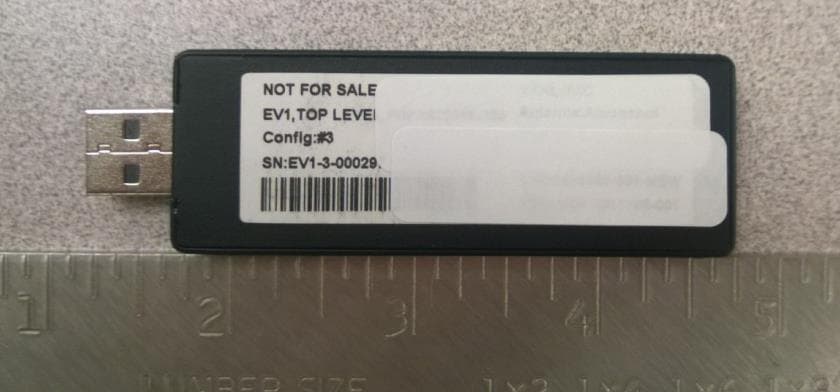
Click to zoom
Application Details
- Equipment Class
- NII - Unlicensed National Information Infrastructure TX
- Date of Grant
- Jul 20, 2015
- Application Purpose
- Original Equipment
- Date of Application
- Jul 19, 2015
- Equipment Note
- 1713
- Frequency Range
- 5745.00000000 - 5825.00000000
- Company
- Microsoft Corporation
- Country
- United States
Documents & Files
Document Text
Text extracted from the exhibit documents filed with the FCC. Open a document above to read the original.
Users Manual
1 XBOX ONE ACCESSORY PRODUCT MANUAL IMPORTANT PRODUCT SAFETY AND WARRANTY INFORMATION This symbol identifies safety and health messages in this product guide Read this guide for important safety and health information for the product that you have purchased. WARNING: Failure to properly set up, use, and care for this product can increase the risk of serious injury, death, property damage, or damage to the product or related accessories. Read this product guide for important safety and health information or go to xbox.com/xboxone/accessories/useinstructions. AGREEMENT TO XBOX ONE LIMITED WARRANTY AND SOFTWARE LICENSE TERMS You must accept the Xbox Terms of Use (including Xbox software terms and game license terms) at xbox.com/live/termsofuse, the software license terms at xbox.com/xboxone/slt, and the Limited Warranty at xbox.com/xboxone/warranty to use your Xbox One console, Xbox accessories and/or Kinect for Xbox sensor. By using the Xbox One console, Xbox accessories and/or Kinect for Xbox One sensor, you agree to be bound by these terms. Please read them. If you do not accept them, do not set up or use your Xbox One console, Xbox accessories and/or Kinect for Xbox One sensor. Return the Xbox Product to Microsoft or your retailer for a refund. ELECTRICAL SAFETY WARNING: As with many other electrical devices, failure to take the following precautions can result in serious injury or death from electric shock, fire, or damage to Xbox One accessories and console: • Use only an approved charging cable. • Do not allow a wireless device or charging cable to become wet. • Unplug the charging cable during lightning storms or when unused for long periods. • To prevent damage, avoid sitting or stepping on a wireless device, its cable, or the cable plug or connector. CAUTION: Cables and Cords To reduce potential trip hazards or entanglement hazards, arrange any cables and cords so that people and pets are not likely to trip over or accidentally pull on them as they move around or walk through the area and do not allow children to play with cables and cords. Go to xbox.com/xboxone/electricalsafety for more information. BATTERY POWERED DEVICES WARNING: Battery Safety The following precautions apply to all products that use disposable or rechargeable batteries including lithium polymer. Improper battery use may result in serious injury, death, property damage, or damage to the product or related accessories as a result of battery fluid leakage, fire, overheating, or explosion. Released battery fluid is corrosive and may be toxic. It can cause skin and eye burns, and is harmful if swallowed. To reduce the risk of injury: Keep batteries out of reach of children. 2 Remove the batteries if they are worn out or before storing your device for an extended period. Always remove old, weak, or worn-out batteries immediately and recycle or dispose of them in accordance with local and national/ regional disposal regulations. If a battery leaks, remove all batteries by reversing the installation steps provided for this product, being careful to keep the leaked fluid from touching your skin or clothes. If fluid from the battery contacts skin or clothes, flush skin with water immediately. Before inserting new batteries, thoroughly clean the battery compartment with a dry cloth, or follow the battery manufacturer’s recommendations for cleanup. • Do not crush, open, puncture, mutilate, heat above 35°C (95°F), apply direct heat to, or dispose of batteries in fire. • Do not mix new and old batteries or batteries of different types (for example, carbon-zinc and alkaline batteries). • Do not allow metal objects to touch the battery terminals on the device; they can become hot and cause burns. • Do not carry or place batteries together with necklaces, hairpins or other metal objects. • Do not leave a battery-powered device in direct sunlight for an extended period, such as on the dash of car during the summer. • Do not immerse batteries in water or allow them to become wet. • Do not connect batteries directly to wall outlets or car cigarette-lighter sockets. • Do not attempt to connect to the battery terminals unless using a Microsoft approved host device. • Do not strike, throw, step on, or subject batteries to severe physical shock. • Do not pierce battery casings in any manner. • Do not attempt to disassemble or modify batteries in any way. • Do not recharge batteries near a fire or in extremely hot conditions. WARNING: Use the Correct Battery Charger Charge rechargeable batteries only with the recharger provided with the product. Using an improper charging method may result in fire or explosion. USE AND CARE OF YOUR XBOX ONE ACCESSORY WARNING: Do Not Attempt Repairs Do not attempt to take apart, open, service, or modify Xbox One accessories. Doing so could present the risk of electric shock, damage, fire, or other hazard. Any evidence of any attempt to open and/or modify this device, including any peeling, puncturing, or removal of any of the labels, will void the Limited Warranty and render the Xbox One accessory ineligible for authorized repair. Modifying any Xbox One accessory can result in a permanent ban from Xbox Live, which is required for game play and some other console uses. Usage and Cleaning WARNING: Do Not Allow Xbox One Accessories to Become Wet To reduce the risk of fire or shock, do not expose the device(s) to rain or other types of moisture. Use in accordance with these instructions: • Do not use accessories near any heat sources. • Only use attachments and accessories specified by Microsoft. • Do not attempt to clean connectors. • Clean only with a dry cloth. For more information, go to xbox.com/xboxone/accessories/productcare. PLAY HEALTHY WARNING: Important Health Warnings about Playing Video Games Photosensitive Seizures A very small percentage of people may experience a seizure when exposed to certain visual images, including flashing lights or patterns that may appear in video games. Even people…
Text truncated - open the document above for the full version.
Cover Letter(s)
Microsoft Corporation is an equal opportunity employer July 13, 2015 Federal Communications Commission Authorization and Evaluation Division 7435 Oakland Mills Road Columbia, Maryland 21046 Cover Letter for FCC application for Certification of FCC ID: C3K1713 TO WHOM IT MAY CONCERN This Model 1713 is an 802.11 a/b/g/n USB radio device operating at 2.4G and 5GHz bands. It is a self-contained device and receives power from a USB host. It communicates via the PC USB port. This is to seek an original certification on this Model 1713, as compliant with FCC 15.247 and 15.407. Sincerely, Kitty Tam Compliance Engineer, Microsoft Corporation.
Cover Letter(s)
Microsoft Corporation is an equal opportunity employer Subject: Authorized signatories May 18, 2015 Federal Communications Commission Authorization and Evaluation Division 7435 Oakland Mills Road Columbia, Maryland 21046 A G E N C Y A U T H O R I Z A T I O N L E T T E R F O R M I C R O S O F T E M P L O Y E E S To whom it may concern, We, the undersigned, Microsoft® Corporation hereby authorize the following, to act on our behalf, as our agent, in all matters relating to all processes required according to FCC Part 15 for Microsoft® Corporation products (Grantee Code:C3K): Hasnain Syed Kitty Tam Anindita Mitra David Johnson Michael Boucher Pamela Galvan Sajay Jose Jennifer Liu Joseph Dizon Elaine Reeves Jojo Malliyakal Wei Sun Zachary Gray Daniel Salinas Shoaib Khan Johnny Deng Robert Towne Chip Schulman Andy Jia Lang Shen Eugene Wong Bill Huang Albert Huang Tim Calland Joy Alegria Ellis Lee Angus McGill If you have any questions regarding the authorization, please don’t hesitate to contact me. Sincerely, Stephen M. Stegner Compliance Engineer Microsoft Corporation
Cover Letter(s)
Microsoft Corporation is an equal opportunity employer July 17, 2015 Federal Communications Commission Authorization and Evaluation Division 7435 Oakland Mills Road Columbia, Maryland 21046 Subject: Confidentiality request regarding application for certification of FCC ID: C3K1713 TO WHOM IT MAY CONCERN Pursuant to Sections 0.457 and 0.459 of the Commission’s Rules, the Applicant hereby requests confidential treatment of information accompanying this Application as outlined below: Block Diagram Schematics Operational Description The above materials contain trade secrets and proprietary information not customarily released to the public. The public disclosure of these matters might be harmful to the Applicant and provide unjustified benefits to its competitors. The Applicant understands that pursuant to Rule 0.457, disclosure of this Application and all accompanying documentation will not be made before the date of the Grant for this application. Sincerely, Kitty Tam Compliance Engineer, Microsoft Corporation.
Cover Letter(s)
Microsoft Corporation is an equal opportunity employer July 17, 2015 Federal Communications Commission Authorization and Evaluation Division 7435 Oakland Mills Road Columbia, Maryland 21046 Subject: Short-term confidentiality request regarding application for Certification of FCC ID: C3K1713 TO WHOM IT MAY CONCERN Pursuant to CFR 47, Sections 0.457 and 0.459, we request short-term confidential treatment for the following information until January 17, 2016 in order to ensure sensitive business information remains confidential until the actual marketing of the device: • External Photos • Test Setup Photos • User’s Manual • Internal Photos Sincerely, Kitty Tam, Compliance Engineer Microsoft Corporation.
External Photos
Model 1713- External Pictures Top Bottom Side (enroll button side) Other Side USB connector side and opposite side
ID Label/Location Info
Model: 1713 Label Location Proposed Label Design Label Location EUT Side View FCC and IC Label Location
Internal Photos
Model 1713- Internal Pictures Top Bottom Top – Shield can removed
RF Exposure Info
Report V2.0 SAR TEST REPORT for MODEL NO. 1713 FCC ID: C3K1713 Test Report No. S-TR30-FCCSAR-3 Issue Date: 07/20/2015 FCC CFR 47 PART 2.1093 IEEE 1528- 2003 Prepared by Microsoft EMC Laboratory 17760 NE 67th Ct, Redmond WA, 98052, U.S.A. 425-421-9799 [email protected] TESTING CERT #3472.01 Report#: S-TR30-FCCSAR-3 Issued: 07/20/2015 Page 2 of 29 Microsoft EMC Laboratory Record of Revisions Revision Date Section Page(s)Summaryof Changes Author/Revised By: 1.0 06/26/2015 All All First Version Zack Gray 2.0 07/15/2015 All All Removed IC References Zack Gray 4.4 8 Added USB test cable length 8,9 12, 14 Justification on USB Cable length. 3.0 07/20/2015 All All Replaced IEEE 1528-2013 with IEEE 1528-2003 Zack Gray Report#: S-TR30-FCCSAR-3 Issued: 07/20/2015 Page 3 of 29 Microsoft EMC Laboratory Table of Contents Record of Revisions ...................................................................................................................... 2 1 Deviations from Standard ...................................................................................................... 6 2 Facilities and Accreditation .................................................................................................... 6 2.1 TEST FACILITY .............................................................................................................. 6 2.2 ACCREDITATIONS ........................................................................................................ 6 2.3 Test Equipment .............................................................................................................. 6 3 Product Description ............................................................................................................... 7 3.1 TEST CONFIGURATIONS ............................................................................................. 7 3.2 ENVIRONMENTAL CONDITIONS ................................................................................. 7 3.3 EQUIPMENT MODIFICATIONS ..................................................................................... 7 3.4 EQUIPMENT UNDER TEST .......................................................................................... 8 3.4.1 Accessory Test Equipment ...................................................................................... 8 3.5 Supported Air Interfaces and Transmission Configurations ........................................... 8 3.5.1 Supported Air Interfaces .......................................................................................... 8 3.5.2 Transmission Configurations ................................................................................... 8 4 Highest Reported SAR Values .............................................................................................. 9 4.1 SAR Limits ...................................................................................................................... 9 5 Test Equipment List ............................................................................................................. 10 6 Test Methodology ................................................................................................................ 11 7 Conducted RF Average Output Power Measurements ....................................................... 12 7.1 Initial Test Configuration Channel ................................................................................ 12 7.1 WLAN 2.4 GHz Conducted Output Power Measurements ........................................... 12 7.2 WLAN 5 GHz Conducted Output Power Measurements .............................................. 13 7.2.1 5.2 GHz Conducted Measurements (U-NII-1) ....................................................... 13 7.2.2 5.8 GHz Conducted Measurements (U-NII-3) ....................................................... 13 8 Test Configurations .............................................................................................................. 14 8.1 Test Positions ............................................................................................................... 1 4 8.1.1 Test Positions Used .............................................................................................. 15 9 SAR Test Procedures .......................................................................................................... 1 6 10 SAR Test Results ............................................................................................................. 1 8 10.1 General SAR Testing Notes ......................................................................................... 18 10.2 WLAN 2.4 GHz SAR Testing Notes ............................................................................. 18 Report#: S-TR30-FCCSAR-3 Issued: 07/20/2015 Page 4 of 29 Microsoft EMC Laboratory 10.3 WLAN 2.4 GHz SAR Test Results ................................................................................ 18 10.4 WLAN 5 GHz SAR Testing Notes ................................................................................ 19 10.5 WLAN 5.2 GHz SAR Test Results ................................................................................ 19 10.6 WLAN 5.8 GHz SAR Test Results ................................................................................ 19 11 SAR System Verification .................................................................................................. 20 11.1 SAR System Verification Results ................................................................................. 21 12 Tissue-Simulating Liquid Verification ............................................................................... 22 12.1 Tissue-Simulating Liquid Ingredients and Maintenance ............................................... 23 12.2 Tissue-Simulating Liquid Measurements ...................................................................... 25 13 System Specification ...............................................…
Text truncated - open the document above for the full version.
RF Exposure Info
Test Report#: S‐TR30‐FCCSAR‐2 Issued: 07/15/2015 Page 1 of 6 Microsoft EMC Laboratory Plot 1 Date/Time: 5/14/2015 3:56:00 PM Test Laboratory: Microsoft EMC DUT: 1713; Type: USB Dongle; Serial: EV1-4-000667 Communication System: UID 0, 802.11 2.4 GHz (0); Frequency: 2462 MHz Medium parameters used: f = 2462 MHz; σ = 1.938 S/m; ε r = 52.235; ρ = 1000 kg/m 3 Phantom section: Flat Section Measurement Standard: DASY5 (IEEE/IEC/ANSI C63.19-2007) DASY Configuration: Probe: EX3DV4 - SN3939; ConvF(6.9, 6.9, 6.9); Calibrated: 7/17/2014; Sensor-Surface: 2mm (Mechanical Surface Detection), z = 1.0, 33.0 Electronics: DAE4 Sn1383; Calibrated: 7/11/2014 Phantom: ELI v5.0 - Front; Type: QDOVA002AA; Serial: TP:xxxx DASY52 52.8.7(1137); SEMCAD X 14.6.10(7164) Flat-Section MSL/05/14/15 g mode Horizontal Bottom 5 mm 8.5 dBm Tune up 2462 MHz (USB Port)/Area Scan (81x161x1): Interpolated grid: dx=0.8000 mm, dy=0.8000 mm Reference Value = 12.301 V/m; Power Drift = 0.04 dB Fast SAR: SAR(1 g) = 0.196 W/kg; SAR(10 g) = 0.090 W/kg Maximum value of SAR (interpolated) = 0.292 W/kg Flat-Section MSL/05/14/15 g mode Horizontal Bottom 5 mm 8.5 dBm Tune up 2462 MHz (USB Port)/Zoom Scan (9x9x9)/Cube 0: Measurement grid: dx=4mm, dy=4mm, dz=4mm Reference Value = 12.301 V/m; Power Drift = 0.04 dB Peak SAR (extrapolated) = 0.412 W/kg SAR(1 g) = 0.184 W/kg; SAR(10 g) = 0.084 W/kg Maximum value of SAR (measured) = 0.292 W/kg Test Report#: S‐TR30‐FCCSAR‐2 Issued: 07/15/2015 Page 2 of 6 Microsoft EMC Laboratory Plot 2 Date/Time: 5/15/2015 7:56:00 PM Test Laboratory: Microsoft EMC DUT: 1713; Type: USB Dongle; Serial: EV1-4-000667 Communication System: UID 0, CW (0); Frequency: 5220 MHz Medium parameters used: f = 5220 MHz; σ = 5.485 S/m; ε r = 48.339; ρ = 1000 kg/m 3 Phantom section: Flat Section Measurement Standard: DASY5 (IEEE/IEC/ANSI C63.19-2007) DASY Configuration: Probe: EX3DV4 - SN3939; ConvF(4.38, 4.38, 4.38); Calibrated: 7/17/2014; Sensor-Surface: 2mm (Mechanical Surface Detection (Locations From Previous Scan Used)), Sensor- Surface: 2mm (Mechanical Surface Detection), z = 1.0, 23.0 Electronics: DAE4 Sn1383; Calibrated: 7/11/2014 Phantom: ELI v5.0 - Front; Type: QDOVA002AA; Serial: TP:xxxx DASY52 52.8.7(1137); SEMCAD X 14.6.10(7164) Flat-Section MSL 5.2 GHz Band/a mode Horizontal Top 5 mm 8.5 dBm Tune up 5220 MHz (USB Port)/Area Scan (101x211x1): Interpolated grid: dx=0.6000 mm, dy=0.6000 mm Reference Value = 11.442 V/m; Power Drift = 0.10 dB Fast SAR: SAR(1 g) = 0.207 W/kg; SAR(10 g) = 0.061 W/kg Maximum value of SAR (interpolated) = 0.444 W/kg Flat-Section MSL 5.2 GHz Band/a mode Horizontal Top 5 mm 8.5 dBm Tune up 5220 MHz (USB Port)/Zoom Scan (7x7x12)/Cube 0: Measurement grid: dx=4mm, dy=4mm, dz=2mm Reference Value = 11.442 V/m; Power Drift = 0.10 dB Peak SAR (extrapolated) = 1.34 W/kg SAR(1 g) = 0.279 W/kg; SAR(10 g) = 0.070 W/kg Maximum value of SAR (measured) = 0.627 W/kg Test Report#: S‐TR30‐FCCSAR‐2 Issued: 07/15/2015 Page 3 of 6 Microsoft EMC Laboratory Plot 3 Date/Time: 5/27/2015 4:49:29 PM Test Laboratory: Microsoft EMC DUT: 1713; Type: USB Dongle; Serial: EV1-4-000667 Communication System: UID 0, CW (0); Frequency: 5765 MHz Medium parameters used (interpolated): f = 5765 MHz; σ = 6.216 S/m; ε r = 47.866; ρ = 1000 kg/m 3 Phantom section: Flat Section Measurement Standard: DASY5 (IEEE/IEC/ANSI C63.19-2007) DASY Configuration: Probe: EX3DV4 - SN3939; ConvF(3.93, 3.93, 3.93); Calibrated: 7/17/2014; Sensor-Surface: 2mm (Mechanical Surface Detection (Locations From Previous Scan Used)), Sensor- Surface: 2mm (Mechanical Surface Detection), z = 1.0, 23.0 Electronics: DAE4 Sn1383; Calibrated: 7/11/2014 Phantom: ELI v5.0 - Front; Type: QDOVA002AA; Serial: TP:xxxx DASY52 52.8.7(1137); SEMCAD X 14.6.10(7164) Flat-Section MSL 5.8 GHz Band/a mode Vertical Front 5 mm 8.5 dBm Tune up 5765 MHz (USB Port)/Area Scan (101x211x1): Interpolated grid: dx=0.6000 mm, dy=0.6000 mm Reference Value = 6.492 V/m; Power Drift = 0.20 dB Fast SAR: SAR(1 g) = 0.334 W/kg; SAR(10 g) = 0.093 W/kg Flat-Section MSL 5.8 GHz Band/a mode Vertical Front 5 mm 8.5 dBm Tune up 5765 MHz (USB Port)/Zoom Scan (7x7x12)/Cube 0: Measurement grid: dx=4mm, dy=4mm, dz=2mm Reference Value = 6.492 V/m; Power Drift = 0.20 dB Peak SAR (extrapolated) = 1.56 W/kg SAR(1 g) = 0.332 W/kg; SAR(10 g) = 0.085 W/kg Maximum value of SAR (measured) = 0.763 W/kg Test Report#: S‐TR30‐FCCSAR‐2 Issued: 07/15/2015 Page 4 of 6 Microsoft EMC Laboratory Plot 4 Date/Time: 5/12/2015 11:35:02 AM Test Laboratory: Microsoft EMC DUT: Dipole 2450 MHz D2450V2_916; Type: D2450V2; Serial: D2450V2 - SN:916 Communication System: UID 0, CW (0); Frequency: 2450 MHz Medium parameters used: f = 2450 MHz; σ = 1.922 S/m; ε r = 52.302; ρ = 1000 kg/m 3 Phantom section: Flat Section Measurement Standard: DASY5 (IEEE/IEC/ANSI C63.19-2007) DASY Configuration: Probe: EX3DV4 - SN3939; ConvF(6.9, 6.9, 6.9); Calibrated: 7/17/2014; Sensor-Surface: 2mm (Mechanical Surface Detection), z = 1.0, 31.0 Electronics: DAE4 Sn1383; Calibrated: 7/11/2014 Phantom: ELI v5.0 - Front; Type: QDOVA002AA; Serial: TP:xxxx DASY52 52.8.7(1137); SEMCAD X 14.6.10(7164) System Performance Check at Frequencies above 1 GHz/System Check 2450 MHz; d=10mm, Pin=20 dBm, dist=2.0mm (EX-Probe)/Area Scan (71x71x1): Interpolated grid: dx=1.200 mm, dy=1.200 mm Reference Value = 65.454 V/m; Power Drift = 0.08 dB Fast SAR: SAR(1 g) = 5.36 W/kg; SAR(10 g) = 2.45 W/kg Maximum value of SAR (interpolated) = 8.08 W/kg System Performance Check at Frequencies above 1 GHz/System Check 2450 MHz; d=10mm, Pin=20 dBm, dist=2.0mm (EX-Probe)/Zoom Scan (7x7x7) (7x7x7)/Cube 0: Measurement grid: dx=5mm, dy=5mm, dz=5mm Reference Value = 65.454 V/m; Power Drift = 0.08 dB Peak SAR (extrapolated) = 11.0 W/kg SAR(1 g) = 5.38 W/kg; SAR(10 g) = 2.5 W/kg Maximum value of SAR (measured) = 8.24 W/kg Test Report#: S‐TR30‐FCCSAR‐2 Issued: 07/15/2015 Page 5 of 6 Microsoft EMC Laboratory Plot 5 Date/Time: 5/15/2015 1:47:22 PM Test Laborato…
Text truncated - open the document above for the full version.
Test Report
This report must not be used to claim product certification, approval, or endorsement by NVLAP, NIST, or any agency of the federal government of the United States of America. This Report may only be duplicated in its entirety Microsoft Corporation 1713 USB Radio Device FCC 15.207:2015 FCC 15.247:2015 Report # MCSO1731.1 Rev 01 NVLAP Lab Code: 200629-0 CERTIFICATE OF TEST 2014-12-10 Product compliance is the responsibility of the client; therefore, the tests and equipment modes of operation represented in this report were agreed upon by the client, prior to testing. The results of this test pertain only to the sample(s) tested. The specific description is noted in each of the individual sections of the test report supporting this certificate of test. Last Date of Test: May 08, 2015 Microsoft Corporation Model: 1713 USB Radio Device Radio Equipment Testing Standards Specification Method FCC 15.207:2015 ANSI C63.10:2009 FCC 15.247:2015 ANSI C63.10:2009 Results Method Clause Test Description Applied Results Comments 6.2 Powerline Conducted Emissions Yes Pass 6.5, 6.6 Spurious Radiated Emissions Yes Pass 6.7 Band Edge Compliance Yes Pass 6.7 Spurious Conducted Emissions Yes Pass 6.9.1 Occupied Bandwidth Yes Pass 6.10.2 Output Power Yes Pass 6.11.2 Power Spectral Density Yes Pass 7.5 Duty Cycle Yes Pass Deviations From Test Standards None Approved By: Rod Munro, Operations Manager Report No. MCSO1731.1 Rev 012/104 REVISION HISTORY REV 2014.10.14 Revision Number Description Date Page Number 01 Correct references to channel number and transmit frequency for high channel 7/17/15 Various Report No. MCSO1731.1 Rev 013/104 ACCREDITATIONS AND AUTHORIZATIONS REV 2015.2.19 United States FCC - Designated by the FCC as a Telecommunications Certification Body (TCB). Certification chambers, Open Area Test Sites, and conducted measurement facilities are listed with the FCC. A2LA - Accredited by A2LA to ISO / IEC 17065 as a product certifier. This allows Northwest EMC to certify transmitters to FCC and IC specifications. NVLAP - Each laboratory is accredited by NVLAP to ISO 17025 Canada IC - Recognized by Industry Canada as a Certification Body (CB). Certification chambers and Open Area Test Sites are filed with IC. European Union European Commission – Validated by the European Commission as a Conformity Assessment Body (CAB) under the EMC directive and as a Notified Body under the R&TTE Directive. Australia/New Zealand ACMA - Recognized by ACMA as a CAB for the acceptance of test data. Korea MSIP / RRA - Recognized by KCC’s RRA as a CAB for the acceptance of test data. Japan VCCI - Associate Member of the VCCI. Conducted and radiated measurement facilities are registered. Taiwan BSMI – Recognized by BSMI as a CAB for the acceptance of test data. NCC - Recognized by NCC as a CAB for the acceptance of test data. Singapore IDA – Recognized by IDA as a CAB for the acceptance of test data. Israel MOC – Recognized by MOC as a CAB for the acceptance of test data. Hong Kong OFCA – Recognized by OFCA as a CAB for the acceptance of test data. Vietnam MIC – Recognized by MIC as a CAB for the acceptance of test data. SCOPE For details on the Scopes of our Accreditations, please visit: http://www.nwemc.com/accreditations/ http://gsi.nist.gov/global/docs/cabs/designations.html Report No. MCSO1731.1 Rev 014/104 MEASUREMENT UNCERTAINTY TMU.2014.12.03 Measurement Uncertainty When a measurement is made, the result will be different from the true or theoretically correct value. The difference is the result of tolerances in the measurement system that cannot be completely eliminated. To the extent that technology allows us, it has been our aim to minimize this error. Measurement uncertainty is a statistical expression of measurement error qualified by a probability distribution. A measurement uncertainty estimation has been performed for each test per our internal quality document WP 342. The estimation is used to compare the measured result with its "true" or theoretically correct value. The expanded measurement uncertainty (K=2) for each test is on each data sheet. Our measurement data meets or exceeds the measurement uncertainty requirements of the applicable specification; therefore, the test data can be compared directly to the specification limit to determine compliance. The calculations for estimating measurement uncertainty are based upon ETSI TR 100 028 (or CISPR 16-4-2 as applicable), and are available upon request. The following table represents the Measurement Uncertainty (MU) budgets for each of the tests that may be contained in this report. Test + MU - MU Frequency Accuracy (Hz) 0.0007% -0.0007% Amplitude Accuracy (dB) 1.2 dB -1.2 dB Conducted Power (dB) 0.3 dB -0.3 dB Radiated Power via Substitution (dB) 0.7 dB -0.7 dB Temperature (degrees C) 0.7°C -0.7°C Humidity (% RH) 2.5% RH -2.5% RH Voltage (AC) 1.0% -1.0% Voltage (DC) 0.7% -0.7% Field Strength (dB) 4.5 dB -4.5 dB AC Powerline Conducted Emissions (dB) 2.9 dB -2.9 dB Report No. MCSO1731.1 Rev 015/104 FACILITIES REV 2015.2.19 California Labs OC01-13 41 Tesla Irvine, CA 92618 (949) 861-8918 Minnesota Labs MN01-08, MN10 9349 W Broadway Ave. Brooklyn Park, MN 55445 (612)-638-5136 New York Labs NY01-04 4939 Jordan Rd. Elbridge, NY 13060 (315) 554-8214 Oregon Labs EV01-12 22975 NW Evergreen Pkwy Hillsboro, OR 97124 (503) 844-4066 Texas Labs TX01-09 3801 E Plano Pkwy Plano, TX 75074 (469) 304-5255 Washington Labs NC01-05 19201 120 th Ave NE Bothell, WA 9801 (425)984-6600 NVLAP NVLAP Lab Code: 200676-0 NVLAP Lab Code: 200881-0 NVLAP Lab Code: 200761-0 NVLAP Lab Code: 200630-0 NVLAP Lab Code:201049-0 NVLAP Lab Code: 200629-0 Industry Canada 2834B-1, 2834B-3 2834E-1 N/A 2834D-1, 2834D-2 2834G-1 2834F-1 BSMI SL2-IN-E-1154R SL2-IN-E-1152R N/A SL2-IN-E-1017 SL2-IN-E-1158R SL2-IN-E-1153R VCCI A-0029 A-0109 N/A A-0108 A-0201 A-0110 Recognized Phase I CAB for ACMA, BSMI, IDA, KCC/RRA, MIC, MOC, NCC, OFCA US0158 US0175 N/A US0017 US0191 US0157 Report No. MCSO1731.1 Rev 016/…
Text truncated - open the document above for the full version.
Test Report
This report must not be used to claim product certification, approval, or endorsement by NVLAP, NIST, or any agency of the federal government of the United States of America. This Report may only be duplicated in its entirety Microsoft Corporation 1713 USB Radio Device FCC 15.207:2015 FCC 15.407:2015 Report # MCSO1731.2 Rev. 1 NVLAP Lab Code: 200629-0 CERTIFICATE OF TEST 2014-12-10 Product compliance is the responsibility of the client; therefore, the tests and equipment modes of operation represented in this report were agreed upon by the client, prior to testing. The results of this test pertain only to the sample(s) tested. The specific description is noted in each of the individual sections of the test report supporting this certificate of test. Last Date of Test: July 15, 2015 Microsoft Corporation Model: 1713 USB Radio Device Radio Equipment Testing Standards Specification Method FCC 15.207:2015 ANSI C63.10:2009 FCC 15.407:2015 ANSI C63.10:2009 Results Method Clause Test Description Applied Results Comments 6.2 Powerline Conducted Emissions Yes Pass 6.5, 6.6 Spurious Radiated Emissions Yes Pass 6.8 Frequency Stability Yes Pass 6.9.1 Emission Bandwidth Yes Pass 6.9.1 Occupied Bandwidth Yes Pass 6.10.3 Peak Transmit Power Yes Pass 6.11.1 Peak Power Spectral Density Yes Pass 7.5 Duty Cycle Yes Pass Deviations From Test Standards None Approved By: Rod Munro, Operations Manager Report No. MCSO1731.2 Rev. 12/131 REVISION HISTORY REV 2014.10.14 Revision Number Description Date Page Number 01 Correct references to channel number and transmit frequency for high channel 7/17/15 Various Report No. MCSO1731.2 Rev. 13/131 ACCREDITATIONS AND AUTHORIZATIONS REV 2015.2.19 United States FCC - Designated by the FCC as a Telecommunications Certification Body (TCB). Certification chambers, Open Area Test Sites, and conducted measurement facilities are listed with the FCC. A2LA - Accredited by A2LA to ISO / IEC 17065 as a product certifier. This allows Northwest EMC to certify transmitters to FCC and IC specifications. NVLAP - Each laboratory is accredited by NVLAP to ISO 17025 Canada IC - Recognized by Industry Canada as a Certification Body (CB). Certification chambers and Open Area Test Sites are filed with IC. European Union Eur…
Text truncated - open the document above for the full version.
Contact Information
Applicant
Hasnain Syed(SR. DIR EMC/SI&RF COMPLIANCE)
Test Firm
Northwest EMC, Inc.Greg Kiemel
Technical Specifications
| # | Rule Parts | Frequency Range | Power Output |
|---|---|---|---|
| 2 | 15E | 5.75 GHz - 5.83 GHz | 5.00 mW |
Other Applications from Microsoft Corporation
C3K2147
Aug 28, 2026Wireless input device
Equipment Class
DTS - Digital Transmission SystemC3K2148
Aug 12, 2026Portable Computing Device
Equipment Class
DXX - Part 15 Low Power Communication Device TransmitterC3K2149
Aug 12, 2026Portable Computing Device
Equipment Class
DXX - Part 15 Low Power Communication Device TransmitterC3K2152
Aug 11, 2026Wireless Accessory
Equipment Class
DTS - Digital Transmission SystemC3K2150
Aug 06, 2026Portable Computing Device
Equipment Class
DXX - Part 15 Low Power Communication Device Transmitter