C3KMN710Broadband Wireless USB2.0 Adapter
Microsoft Corporation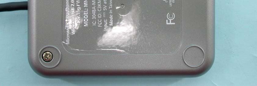
Click to zoom
Application Details
- Equipment Class
- DTS - Digital Transmission System
- Date of Grant
- Feb 09, 2004
- Application Purpose
- Original Equipment
- Date of Application
- Feb 09, 2004
- Equipment Note
- Broadband Wireless USB2.0 Adapter
- Frequency Range
- 2412.00000000 - 2462.00000000
- Company
- Microsoft Corporation
- Country
- United States
Documents & Files
Document Text
Text extracted from the exhibit documents filed with the FCC. Open a document above to read the original.
Users Manual
IMPORTANT SAFETY INFORMATION This manual contains important information about how to safely and properly set up, use, and care for Microsoft Broadband Networking products. Do not take the products apart. Do not attempt to service or repair the products yourself. Refer all servicing to qualified service personnel. Servicing is required when a product has been damaged in any way, such as: O Liquid has been spilled or objects have fallen into the product. O The product has been exposed to rain or moisture, does not operate normally, or has been dropped. General Electrical Precautions As with many other electrical devices, failure to take the following precautions can result in serious injury from electric shock, or fire, or damage to the Microsoft Broadband Networking products. Do not push or insert anything into openings. Take precautions to keep children from putting anything inside the products. Do not overload an extension cord, wall outlet, or other type of receptacle. Do not exceed the stated ratings of cords or receptacles. Use the type of power source indicated on the product. If you are not sure of the type of power supply to your home, consult a qualified electrician. Do not expose the products to liquids or moisture. O Do not use the products near water (for example, sinks, tubs, pools) or expose them to rain, moisture, or dripping or splashing liquids. O Do not place objects filled with liquids, such as beverages or vases, on or near the products. O Do not clean the products with water, liquid cleaners, solvents, or aerosols. Clean the outside of the products properly. Clean only with a dry cloth. Unplug the products during lightning storms or when unused for long periods of time. This symbol is intended to alert the user to the presence of important safety, operating, and maintenance instructions in the literature accompanying the products. Warning To reduce the risk of electric shock, do not expose this product to rain or moisture. 1203 Part No. X10-26439 X1026439_TOC.indd11/19/2003, 8:36 AM1 X1026439_TOC.indd11/19/2003, 8:36 AM2 contents 1 | Introduction: Welcome to Wireless-G...................................................................1 CardBus Technology.....................................................................................2 The Wireless USB 2.0 Adapter.....................................................................3 USB Technology.............................................................................................3 Adapter Status Lights...................................................................................4 About Wireless (Radio) Connections...............................................................4 Types of Wireless Networks..........................................................................5 Placement of Wireless Components............................................................6 Understanding Wireless Transmission Standards......................................7 2 | Setup: Using the Setup Wizard..............................................................................9 Step 1: Gather Components, Tools, and Information.................................9 Step 2: Run the Setup Wizard...................................................................10 Step 3: Insert the Adapter into Your Computer........................................11 Step 4: Configure the Adapter...................................................................12 Step 5: Test Your Network Connections...................................................12 3 | Network Activities: Sharing Resources and Joining Other Networks............13 Logging on to Your Network..........................................................................14 Using an Internet Connection over a Network.............................................14 Using the Broadband Network Utility...........................................................15 Using Files and Folders over a Network.......................................................16 Step 1: Make your files and folders available to the network.................17 Step 2: Access shared files.......................................................................19 Using a Printer over a Network.....................................................................19 Using Other Peripheral Devices over a Network..........................................20 About Reading E-Mail Messages on a Network..........................................20 Playing Games on Your Network and on the Internet.................................21 Creating a Computer-to-Computer (Ad Hoc) Network.................................21 Joining an Available Wireless Network........................................................23 4 | Network Management: Understanding Network Maintenance & Security .25 Monitoring Your Network..............................................................................25 View Status.................................................................................................25 View Network Devices................................................................................25 View Adapter Settings................................................................................26 Updating Software.........................................................................................26 X1026439_TOC.indd11/19/2003, 8:36 AM3 iv Microsoft Broadband Networking Wireless Adapter User’s Guide Making Your Network More Secure..............................................................26 Help Protect Your Network from Computer Viruses.................................27 Help Protect Your Network from Hackers.................................................27 Help Protect Your Network from Unauthorized Access............................28 5 | Troubleshooting: Finding Answers to Common Problems.............................29 Setup and Hardware Problems....................................................................2…
Text truncated - open the document above for the full version.
Users Manual
M user’s guide M www.microsoft.com/broadbandnetworking 1203 Part No. X10-26439 Microsoft ® Broadband Networking Wireless-G Adapter MN-710/MN-720 X1026439_CVR.indd11/19/2003, 8:23 AM1 Caution Any changes or modifications not expressly approved by Microsoft could void the user’s authority to operate this device. Not intended for use in industrial, medical or scientific settings. Do not use onboard an aircraft or in hazardous locations such as a gas station or other explosive environment. For indoor use only. Notebook Adapter: This device has been tested for compliance with FCC RF Exposure (SAR) limits in the typical laptop computer configuration and this device can be used in desktop or laptop computers with side mounted PCMCIA slots. The antennas used with this transmitter must not be co-located or operating in conjunction with any other antenna or transmitter within the host device. Do not touch or re-orient the antenna while the device is transmitting. USB 2.0 adapter: Device should be located at least 20 cm (8 inches) away from any human body in order to meet FCC exposure limits. The antennas used with this transmitter must not be co-located or operating in conjunction with any other antenna or transmitter. Do not touch or re-orient the antenna while the device is transmitting. Attention Tout changement ou modification apporté à ce dispositif non expressément autorisé par Microsoft est à proscrire. Ne pas utiliser ce dispositif dans une application industrielle, médicale ou scientifique. Ne pas utiliser dans un avion ou en présence de vapeur explosive (station-service). N’utiliser qu’à l’intérieur. Carte réseau pour ordinateur portable: Ce dispositif radio a été évalué pour son débit d’absorption spécifique (DAS) et respecte les limites d’exposition RF des personnes, telles que spécifiées dans la procédure CNR 102 lorsque utilisé dans le port PCMCIA d’un ordinateur portable ou de table. Les antennes de ce dispositif transmetteur ne doivent ni être copositionnées ou ni utilisées en conjonction avec quelque autre antenne ou transmetteur faisant partie de l ’ordinateur hôte. Ne touchez pas à l’antenne lorsque l’appareil est en fonction. Adaptateur USB: Ce dispositif doit être à plus de 20 cm (8 pouces) de toute personne. Les antennes de ce dispositif transmetteur ne doivent ni être copositionnées ou ni utilisées en conjonction avec quelque autre antenne ou transmetteur faisant partie de l ’ordinateur hôte. Ne touchez pas à l’antenne lorsque l’appareil est en fonction. Please retain this manual for future reference. Veuillez conserver ce manuel pour future référence. Information in this document, including URL and other Internet Web site references, is subject to change without notice. Unless otherwise noted, the example companies, organizations, products, domain names, e-mail addresses, logos, people, places, and events depicted herein are fictitious, and no association with any real company, organization, product, domain name, e-mail address, logo, person, place, or event is intended or should be inferred. Complying with all applicable copyright laws is the responsibility of the user. Without limiting the rights under copyright, no part of this document may be reproduced, stored in, or introduced into a retrieval system, or transmitted in any form or by any means (electronic, mechanical, photocopying, recording, or otherwise), or for any purpose, without the express written permission of Microsoft Corporation. Microsoft may have patents, patent applications, trademarks, copyrights, or other intellectual property rights covering subject matter in this document. Except as expressly provided in any written license agreement from Microsoft, the furnishing of this document does not give you any license to these patents, trademarks, copyrights, or other intellectual property. © 2003 Microsoft Corporation. All rights reserved. Microsoft and Windows are registered trademarks of Microsoft Corporation in the United States and/or other countries. UPnP is a trademark of UPnP Implementers Corp. Wi-Fi is a registered trademark and Wi-Fi Protected Access is a trademark of Wi-Fi Alliance. The names of actual companies and products mentioned herein may be the trademarks of their respective owners. My Network Settings Use this page to record your network settings. For information about locating these settings, see Appendix A. Workgroup or domain name: Base Station, gateway, or router password: (Microsoft Base Station default password=admin) Wireless Settings Record the information used to configure a computer for wireless access to your network here. All computers accessing your network with a wireless connection need to use the same wireless settings. Wireless network name (SSID): WEP key or WPA passphrase: Wireless channel (ad-hoc networks only): Wide Area Network Settings Complete this section only if your network has a base station (gateway or router). You can obtain this information from your Internet service provider (ISP). Your ISP may not require all of the settings listed below. Dynamic IP (DHCP) Settings Complete this section only if your ISP uses a DHCP connection. Host name: Adapter MAC address: Static IP Address Settings Complete this section only if your ISP has assigned you a specific IP address. Static IP address: Subnet mask: IP gateway address: Primary DNS server: Secondary DNS server: PPPoE Settings Complete this section only if your ISP uses PPPoE. User name: Password: Service name: X1026439_CVR.indd11/19/2003, 8:23 AM2
Cover Letter(s)
Microsoft Corporation One Microsoft Way, Redmond WA 98052-6399, U.S.A Tel: +1 425 706-2697 E-mail: [email protected] December 1, 2003 Federal Communications Commission 7435 Oakland Mills Road Columbia, MD 21046 FCC ID: C3KMN710 Confidentiality Request Pursuant to Sections 0.457 and 0.459 of the Commission’s Rules, the Applicant hereby requests confidential treatment of information accompanying this Application as outlined below: Schematics Block Diagram The above materials contain trade secrets and proprietary information not customarily released to the public. The public disclosure of these matters might be harmful to the Applicant and provide unjustified benefits to its competitors. The Applicant understands that pursuant to Rule 0.457, disclosure of this Application and all accompanying documentation will not be made before the date of the Grant for this application. Sincerely, Stephen Stegner EMC/Safety Engineer Microsoft Corporation
External Photos
Page 1 CONSTRUCTION PHOTOS OF EUT Page 2 Page 3
Internal Photos
Page 4 Page 5 Page 6 Page 7
Operational Description
CONFIDENTIALITY STATEMENT The information contained in this facsimile message is legally privileged and confidential information intended only for the use of the addressee listed on this cover sheet. If the reader of this message is not the intended recipient, you are hereby notified that any dissemination, distribution or copy of this facsimile is strictly prohibited. If you have received this facsimile in error, please immediately notify us by telephone at the number listed on this cover sheet and return the original message to us at the above address via the United States Postal Service. We will reimburse any costs you incur in notifying us and returning the message to us. Thank you. A. Bovee 1/15/2004; Operational_MN-710.doc Microsoft Corporation is an equal opportunity employer. Operational Statement Microsoft Broadband Networking Wireless USB2.0 Adapter Model MN-710 The MN-710 is a USB Wireless Adapter used to connect a home user's PC wirelessly to a home computer network and to the Internet when the user has internet connectivity. This allows use of an existing home 802.11b or 802.11g wireless network, managed by a wireless Access Point, to accommodate a new PC. The MN-710 is a USB2.0 device and is backward compatible with earlier versions of USB. MN-710 securely shares a broadband modem and internet connection with other wireless devices in a home environment, and allows network access with other network devices in the household or over the internet The MN-710 communicates with a wireless base station utilizing IEEE 802.11g radio protocols (also compatible with IEEE 802.11b wireless devices). It provides up to 54 Mbps radio transmission (with fallbacks to 24, 12, 11, 5.5, 2 and 1 Mbps) in the 2.4 GHz unlicensed Industrial Scientific Medical (ISM) radio band. The user sets up the MN710 by connecting it to the user's USB port. Easy-to-set-up software allows the user to configure the MN710. The MN-710 is powered by 5VDC (SELV) from the USB connection. This voltage is converted by regulators into 3.3, 2.84, 2.5, and 1.8VDC to power the analog and digital circuits. Crystal oscillators running at 32.768KHz, 30MHz, and 40MHz provide timing for the baseband IC and USB controller. The channel frequency is provided by a VCO. 802.11g/b parameters, USB parameters, and the PID/VID are stored in EEPROM. The MN-710 antenna is permanently attached. The printed circuit board incorporates both analog and digital ground planes for the purposes of signal integrity and EMI reduction.
Test Report
Report No.: D921208R021Issued: December 12, 2003 FCC DoC TEST REPORT REPORT NO.: D921208R02 MODEL NO.: MN-710 RECEIVED: December 05, 2003 TESTED: December 05 ~ December 10, 2003 APPLICANT: Microsoft Corporation ADDRESS: One Microsoft Way,Redmond WA 98052-6399, U.S.A ISSUED BY: Advance Data Technology Corporation LAB LOCATION: 47 14th Lin, Chiapau Tsun, Linko, Taipei, Taiwan, R.O.C. This test report consists of 28 pages in total. It may be duplicated completely for legal use with the approval of the applicant. It should not be reproduced except in full, without the written approval of our laboratory. The client should not use it to claim product endorsement by CNLA, NVLAP or any government agencies. The test results in the report only apply to the tested sample. 0528 ILAC MRA Lab Code: 200102-0 Report No.: D921208R022Issued: December 12, 2003 Table of Contents 1CERTIFICATION ........................................................................................... 3 2SUMMARY OF TEST RESULTS................................................................... 4 3GENERAL INFORMATION ........................................................................... 5 3.1GENERAL DESCRIPTION OF EUT.............................................................. 5 3.2DESCRIPTION OF TEST MODES................................................................ 6 3.3GENERAL DESCRIPTION OF APPLIED STANDARDS ............................... 6 3.4DESCRIPTION OF SUPPORT UNITS .......................................................... 7 3.5CONFIGURATION OF SYSTEM UNDER TEST........................................... 7 4TEST TYPES AND RESULTS....................................................................... 8 4.1CONDUCTED EMISSION MEASUREMENT ................................................ 8 4.1.1LIMITS OF CONDUCTED EMISSION MEASUREMENT.............................. 8 4.1.2TEST INSTRUMENTS .................................................................................. 8 4.1.3TEST PROCEDURES................................................................................... 9 4.1.4DEVIATION FROM TEST STANDARD ......................................................... 9 4.1.5TEST SETUP .............................................................................................. 10 4.1.6EUT OPERATING CONDITIONS................................................................ 10 4.1.7TEST RESULTS...........................................................................................11 4.2RADIATED EMISSION MEASUREMENT ................................................... 17 4.2.1LIMITS OF RADIATED EMISSION MEASUREMENT................................. 17 4.2.2TEST INSTRUMENTS ................................................................................ 18 4.2.3TEST PROCEDURES................................................................................. 19 4.2.4DEVIATION FROM TEST STANDARD ....................................................... 19 4.2.5TEST SETUP .............................................................................................. 20 4.2.6EUT OPERATING CONDITIONS................................................................ 20 4.2.7TEST RESULTS.......................................................................................... 21 4.2.8TEST RESULTS.......................................................................................... 23 5PHOTOGRAPHS OF THE TEST CONFIGURATION.................................. 26 6INFORMATION ON THE TESTING LABORATORIES ................................ 28 Report No.: D921208R023Issued: December 12, 2003 1 CERTIFICATION PRODUCT : Microsoft ® Broadband Networking Wireless USB 2.0 Adapter (Receiver Part) BRAND NAME : Microsoft ® MODEL NO. : MN-710 TEST ITEM: ENGINEERING SAMPLE APPLICANT : MICROSOFT CORPORATION STANDARDS : FCC Part 15, Subpart B, class B, ANSI C63.4-1992 We, Advance Data Technology Corporation, hereby certify that one sample of the designation has been tested in our facility from December 05 ~ December 10, 2003. The test record, data evaluation and Equipment Under Test (EUT) configurations represented herein are true and accurate accounts of the measurements of the sample's EMC characteristics under the conditions herein specified. PREPARED BY: , DATE: December 12, 2003 APPROVED BY: Wendy Liao , DATE: December 12, 2003 Ellis Wu / Manager Report No.: D921208R024Issued: December 12, 2003 2 SUMMARY OF TEST RESULTS The EUT has been tested according to the following specifications: Standard Section Test TypeResultRemarks Conducted Emission PASS Meet the requirement of limit Minimum passing margin is –7.10dB at 0.168 MHz FCC Part 15, Subpart B, class B Radiated Emissions PASS Meet the requirement of limit Minimum passing margin is –4.42dB at 195.23 MHz NOTE: The information of measurement uncertainty is available upon the customer’s request. Report No.: D921208R025Issued: December 12, 2003 3 GENERAL INFORMATION 3.1 GENERAL DESCRIPTION OF EUT PRODUCT Microsoft ® Broadband Networking Wireless USB 2.0 Adapter (Receiver Part) MODEL NO. MN-710 POWER SUPPLY 5.0Vdc from host equipment MODULATION TYPE BPSK, QPSK, CCK, 16QAM, 64QAM MODULATION TECHNOLOGY DSSS, OFDM TRANSFER RATE 54/48/36/24/18/12/11/9/6/5.5/2/1Mbps FREQUENCY RANGE 2412MHz ~ 2462MHz NUMBER OF CHANNEL 11 MAXIMUM OUTPUT POWER 18.30dBm ANTENNA TYPE Dipole antenna with 2.5dBi gain DATA CABLE USB cable (1.8m Shielded) I/O PORTS USB ASSOCIATED DEVICES NA NOTE: 1. The EUT operates in the 2.4GHz frequency spectrum with throughput of up to 54Mbps. 2. The EUT complies with IEEE 802.11g draft standards, and backwards compatible with IEEE 802.11b products. 3. For a more detailed features description, please refer to the manufacturer's specifications or User's Manual. Report No.: D921208R026Issued: December 12, 2003 3.2 DESCRIPTION OF TEST MODES Eleven channels are provided to this EUT. ChannelFrequencyChannelFrequency 12412 MHz72442 MHz 22417 MHz82447 MHz 32422 MHz92452 MHz 42427 MHz102457 MH…
Text truncated - open the document above for the full version.
Test Report
Report No.: RF930109R011Issued: January 13, 2004 FCC TEST REPORT REPORT NO.: RF930109R01 MODEL NO.: MN-710 RECEIVED: January 8, 2004 TESTED: January 8 ~ January 10, 2004 APPLICANT: Microsoft Corporation ADDRESS: One Microsoft Way, Redmond WA 98052-6399, U.S.A. ISSUED BY: Advance Data Technology Corporation LAB LOCATION: 47 14th Lin, Chiapau Tsun, Linko, Taipei, Taiwan, R.O.C. This test report consists of 64 pages in total. It may be duplicated completely for legal use with the approval of the applicant. It should not be reproduced except in full, without the written approval of our laboratory. The client should not use it to claim product endorsement by CNLA or any government agencies. The test results in the report only apply to the tested sample. 0528 ILAC MRA Report No.: RF930109R012Issued: January 13, 2004 Table of Contents 1CERTIFICATION .......................................................................................................4 2SUMMARY OF TEST RESULTS ...............................................................................5 3GENERAL INFORMATION........................................................................................6 3.1GENERAL DESCRIPTION OF EUT ..........................................................................6 3.2DESCRIPTION OF TEST MODES ............................................................................7 3.3GENERAL DESCRIPTION OF APPLIED STANDARDS ...........................................7 3.4DESCRIPTION OF SUPPORT UNITS ......................................................................8 3.5CONFIGURATION OF SYSTEM UNDER TEST.......................................................9 4TEST TYPES AND RESULTS .................................................................................10 4.1CONDUCTED EMISSION MEASUREMENT ..........................................................10 4.1.1LIMITS OF CONDUCTED EMISSION MEASUREMENT........................................10 4.1.2TEST INSTRUMENTS.............................................................................................10 4.1.3TEST PROCEDURES ............................................................................................. 11 4.1.4DEVIATION FROM TEST STANDARD ................................................................... 11 4.1.5TEST SETUP...........................................................................................................12 4.1.6EUT OPERATING CONDITIONS ............................................................................12 4.1.7TEST RESULTS ......................................................................................................13 4.2RADIATED EMISSION MEASUREMENT ...............................................................19 4.2.1LIMITS OF RADIATED EMISSION MEASUREMENT.............................................19 4.2.2TEST INSTRUMENTS.............................................................................................20 4.2.3TEST PROCEDURES .............................................................................................21 4.2.4DEVIATION FROM TEST STANDARD ...................................................................21 4.2.5TEST SETUP...........................................................................................................22 4.2.6EUT OPERATING CONDITIONS ............................................................................22 4.2.7.TEST RESULTS ......................................................................................................23 4.2.8.TEST RESULTS (FOR CCK)...................................................................................25 4.2.9.TEST RESULTS (FOR OFDM)................................................................................28 4.36dB BANDWIDTH MEASUREMENT.......................................................................31 4.3.1LIMITS OF 6dB BANDWIDTH MEASUREMENT ....................................................31 4.3.2TEST INSTRUMENTS.............................................................................................31 4.3.3TEST PROCEDURE................................................................................................32 4.3.4DEVIATION FROM TEST STANDARD ...................................................................32 4.3.5TEST SETUP...........................................................................................................32 4.3.6EUT OPERATING CONDITIONS ............................................................................32 4.3.7TEST RESULTS ......................................................................................................33 Report No.: RF930109R013Issued: January 13, 2004 4.4MAXIMUM PEAK OUTPUT POWER ......................................................................41 4.4.1LIMITS OF MAXIMUM PEAK OUTPUT POWER MEASUREMENT .......................41 4.4.2TEST INSTRUMENTS.............................................................................................41 4.4.3TEST PROCEDURES .............................................................................................42 4.4.4DEVIATION FROM TEST STANDARD ...................................................................42 4.4.5TEST SETUP...........................................................................................................42 4.4.6EUT OPERATING CONDITIONS ............................................................................42 4.4.7TEST RESULTS ......................................................................................................43 4.5POWER SPECTRAL DENSITY MEASUREMENT..................................................44 4.5.1LIMITS OF POWER SPECTRAL DENSITY MEASUREMENT ...............................44 4.5.2TEST INSTRUMENTS.............................................................................................44 4.5.3TEST PROCEDURE..............................................................................................…
Text truncated - open the document above for the full version.
Test Setup Photos
Page 1 PHOTOGRAPHS OF THE TEST CONFIGURATION Page 2
Contact Information
Applicant
Hasnain Syed(SR. DIR EMC/SI&RF COMPLIANCE)
Technical Contact
CKC Laboratories, Inc.Mary Ellen Clayton
[email protected]209-966-5240
5473-A Clouds Rest · Mariposa, California · United States
Non-Technical Contact
CKC Laboratories, Inc.Mary Ellen Clayton
[email protected]209-966-5240
Test Firm
Advance Data Tech. Corp. Hsin Chu EMCStephen Chen
Technical Specifications
| # | Rule Parts | Frequency Range | Power Output |
|---|---|---|---|
| 1 | 15C | 2.41 GHz - 2.46 GHz | 83.00 mW |
Other Applications from Microsoft Corporation
C3K2147
Aug 28, 2026Wireless input device
Equipment Class
DTS - Digital Transmission SystemC3K2148
Aug 12, 2026Portable Computing Device
Equipment Class
DXX - Part 15 Low Power Communication Device TransmitterC3K2149
Aug 12, 2026Portable Computing Device
Equipment Class
DXX - Part 15 Low Power Communication Device TransmitterC3K2152
Aug 11, 2026Wireless Accessory
Equipment Class
DTS - Digital Transmission SystemC3K2150
Aug 06, 2026Portable Computing Device
Equipment Class
DXX - Part 15 Low Power Communication Device Transmitter