C3KMN740Microsoft Wireless Ethernet Bridge for X Box
Microsoft Corporation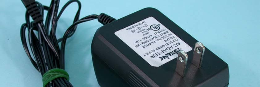
Click to zoom
Application Details
- Equipment Class
- DTS - Digital Transmission System
- Date of Grant
- Sep 25, 2003
- Application Purpose
- Original Equipment
- Date of Application
- Sep 25, 2003
- Equipment Note
- Microsoft Wireless Ethernet Bridge for X Box
- Frequency Range
- 2412.00000000 - 2462.00000000
- Company
- Microsoft Corporation
- Country
- United States
Documents & Files
Document Text
Text extracted from the exhibit documents filed with the FCC. Open a document above to read the original.
Users Manual
connect whether you are ready to begin 2 wireless adapter install 3 Xbox Dashboard update This Start Here guide will help you set up your Microsoft ® Broadband Networking Xbox ® Wireless Adapter on a Microsoft Xbox video game system. Before you go to the next page, make sure that you have everything you need to begin. To play games on the Xbox Live ™ online game service, you need: OExisting network that has a wireless router, base station, or gateway OXbox game that has the Xbox Live logo OSubscription to Xbox Live service (sold separately) OBroadband Internet connection (cable or DSL) To create a wireless connection for System Link (console-to-console) play, you need: OTwo Xbox video game systems OSecond Xbox wireless adapter OXbox game that supports System Link play © 2003 Microsoft Corporation. All rights reserved. 0803 Part No. X09-97724 check If you just purchased a router, base station, or gateway, set it up before setting up this adapter. To connect the Microsoft Xbox Wireless Adapter Leave your Xbox console and any wireless networking devices (such as a router) turned on when you connect the wireless adapter. For suggestions on placing your wireless networking devices for best performance, see Chapter 2 of the User’s Guide. Insert the Xbox wireless adapter setup disc into the disc tray of your Xbox console. Your Xbox Dashboard will be updated if necessary. Setup then detects available wireless networks, and displays them on the Select Network screen. Ethernet cable O...and you want to connect to an existing network, select the network name. Setup will detect many of the settings that the Xbox wireless adapter needs for connect- ing to that network. Go to step 4 on the next page. O...and you want to set up the first Xbox console in a new System Link connection, select Other, enter a network name on the Network Name screen, and then go to step 4 on the next page. When you set up the second Xbox console, the network name that you specify will appear on the Select Network screen. To power supply ...and then connect the other end of the Ethernet cable to the Ethernet port on your Xbox console. Connect one end of the provided Ethernet cable to the To Xbox port on your Xbox wireless adapter... 1 Plug one end of the power supply into the Power port on the Xbox wireless adapter, and then plug the other end into an electrical outlet. 3 2 Before using this product, read both the Xbox wireless adapter User’s Guide and the Xbox Instruction Manual for important safety information and health warnings. Please retain these manuals for future reference. If the Select Network screen appears... If the Select Network screen does not appear... O...and you want to connect to an existing network, see Chapter 3 in the User’s Guide for trouble- shooting information. O...and you want to set up the first Xbox console in a new System Link connection, skip to step 4 on the next page to specify and describe your wireless network. M ic r Micr o so f osof t B r t Br o a d ba n d N e oadband Ne twtw o r or kin g king Xbo x Wx W ir eless Aeless A dapdap t er M N -7 MN-7 4040 M icr Micr os of osof t Brt Br oadband Neoadband Ne tw oror kingking XboXbo x Wx W ir eless Aeless A dap t erer MN-7MN-7 40 Box Contents Xbox wireless adapter (MN-740) Power supply cord Ethernet cable Xbox wireless adapter setup disc User’s Guide and Start Here guide start here test5 network connections configure4 wireless adapter On the Wireless Settings screen, enter information about your network. Try one of these tests to confirm that the setup of your adapter was successful: O If you added your Xbox console to an existing network with a shared broadband Internet connection, start a game that is supported by Xbox Live. Make sure that you can access the service with your account. O If you connected two Xbox consoles, start a game that supports System Link play. Use the System Link play option in the game, and make sure that you can play with the team that is using the other Xbox console. O If you have other Microsoft Broadband Networking products installed on your network, start the Broadband Network Utility from a computer on your network. Make sure that your Xbox wireless adapter appears under Network Devices. To troubleshoot network problems Xbox ® Wireless Adapter MN-740 Microsoft ® Broadband Networking m Check your wireless connection status on the Wireless Status screen: O If your adapter is correctly configured for the network, your connection status will appear as Connected. O If your connection status appears as Not Connected, select Settings to review your wireless settings. Check out the following resources to help identify and solve common problems: O The User’s Guide contains basic troubleshooting instructions and technical support information. O Our Web site at www.microsoft.com/ broadbandnetworking includes the most recent troubleshooting information and product updates. An adapter password is required for installing adapter updates. The password must contain no fewer than 3 characters and no more than 16. If you do not specify a password, you must use the default password, admin, to update your adapter. If you are connecting to an existing network that you chose on the Select Network screen: O Specify the Security Type and Security Key if your network uses wireless security. Do not change any other settings on this screen. The Xbox wireless adapter supports both 128-bit and 64- bit WEP. The security type and security key that you specify on your Xbox wireless adapter must match those specified on your other network devices. If you are setting up the first Xbox console for System Link (console-to-console) play: O Select Network Name to create a wireless network name (SSID). This name is case sensitive. When you set up the wireless adapter on your second Xbox console, this name will appear on the Select Network screen. O Select Network Mode, and then specify the network mode as ad hoc 802.11b/g. O Select Channel to choose a ch…
Text truncated - open the document above for the full version.
Cover Letter(s)
POWER OF ATTORNEY To whom it may concern: By this Power of Attorney, MICROSOFT CORPORATION, a Washington corporation with principal offices located at One Microsoft Way, Redmond, WA 98052, hereby authorizes, Advance Data Technology Corp. (ADT) of Taiwan to act on our behalf in all matters relating to all processes required in the FCC approval process according to CFR 47 Part 15C for Model MN-740 (C3KMN740). Any and all acts carried out by ADT on our behalf shall have the same effects as acts of our own. This Power of Attorney will expire on December 13, 2003, unless earlier revoked in writing. If you have any questions regarding the authorization, please don’t hesitate to contact us. Thank you! Sincerely yours, Stephen Stegner EMC/Safety Engineer Microsoft Corporation TEL:+1 425 706-2697 FAX:+1 425 936-7329 [email protected]
Cover Letter(s)
CONFIDENTIALITY STATEMENT The information contained in this facsimile message is legally privileged and confidential information intended only for the use of the addressee listed on this cover sheet. If the reader of this message is not the intended recipient, you are hereby notified that any dissemination, distribution or copy of this facsimile is strictly prohibited. If you have received this facsimile in error, please immediately notify us by telephone at the number listed on this cover sheet and return the original message to us at the above address via the United States Postal Service. We will reimburse any costs you incur in notifying us and returning the message to us. Thank you. Microsoft Corporation is an equal opportunity employer. FEDERAL COMMUNICATIONS COMMISSION (FCC) DECLARATION OF CONFORMITY (DoC) I/We Microsoft Corporation Of One Microsoft Way Redmond, WA 98052-6399 www.microsoft.com Declare under our sole responsibility that the product(s): Model(s): MN-740 (Microsoft Broadband Networking Xbox Wireless Adapter) FCC ID# (if applicable): C3KMN740 to which this declaration relates, complies with Part 15 of the FCC Rules. Operation is subject to the following two conditions: (1) this device may not cause harmful interference, and (2) this device must accept any interference received, including interference that may cause undesired operation. July 31, 2003 (signature) Stephen Stegner EMC/Safety Engineer Microsoft Corporation Date
Cover Letter(s)
FCC ID: C3KMN740 Federal Communications Commission Authorization and Evaluation Division Confidentiality Request Pursuant to Sections 0.457 and 0.459 of the Commission’s Rules, the Applicant hereby requests confidential treatment of information accompanying this Application as outlined below: Schematics Block Diagram Bill of Materials The above materials contain trade secrets and proprietary information not customarily released to the public. The public disclosure of these matters might be harmful to the Applicant and provide unjustified benefits to its competitors. The Applicant understands that pursuant to Rule 0.457, disclosure of this Application and all accompanying documentation will not be made before the date of the Grant for this application. Sincerely, Stephen Stegner EMC/Safety Engineer Microsoft Corporation TEL:+1 425 706-2697 FAX:+1 425 936-7329 [email protected]
External Photos
Page 1 ANNEX PHOTOGRAPHS OF EUT Page 2 Page 3
ID Label/Location Info
Page 1 Label Location
ID Label/Location Info
MAC: PID: 2 in 1 sticker
Internal Photos
Page 4 Page 5 Page 6 Page 7 Page 8 Page 9 Page 10
Operational Description
FCC ID: C3KMN740 ADT No.920723R01 Operational Description This device is a Microsoft Broadband Networking Wireless Ethernet Bridge for X box which operates in the 2.4GHz frequency spectrum with throughput of up to 54Mbps which OFDM technique will be applied. If the signal to noise radio is too poor which could not support 54Mbps, the 11Mbps data rate with CCK technique will be applied. The transmitter of the EUT is powered by AC adapter. The antenna is Dipole antenna with Reversed SMA connector. The other instruction, please have a look at the users manual.
RF Exposure Info
FCC ID: C3KMN740 ADT No.: 920723R01 FCC TEST REPORT REPORT NO.: RF920723R01 MODEL NO.: MN-740 ACCORDING: FCC Guidelines for Human Exposure IEEE C95.1 APPLICANT: Microsoft Corporation ADDRESS: One Microsoft Way,Redmond WA 98052-6399, U.S.A ISSUED BY: Advance Data Technology Corporation LAB LOCATION: 47 14th Lin, Chiapau Tsun, Linko, Taipei, Taiwan, R.O.C. 0528 ILAC MRA Lab Code: 200102-0 FCC ID: C3KMN740 ADT No.: 920723R01 RF Exposure Measurement (Mobile Device) 1. Introduction 2.4GHz frequency band is regarded specially as a dangerous band for its heating harmfulness to the human body. That’s why microwave oven is operating in this frequency band. The manufacturer whose product is working in this frequency band is obligatory to prove the harmfulness of his product. In this document, we try to prove the safety of radiation harmfulness to the human body for our product. The limit for Maximum Permissible Exposure (MPE) specified in FCC 1.1310 is followed. The Gain of the antenna used in this product is measured in a Fully Anechoic Chamber (FAC), and the maximum total power input to the antenna is measured. Through the Friis transmission formula and the maximum gain of the antenna, we can calculate the distance, away from the product, where the limit of MPE is reached. 2. Classification This device is not fixed inside the host equipment, it is connected with host through wire. So it is easy to be re-located in the place where at least 20cm far away from the body of the user. Warning statement to the user for keeping at least 20cm or more separation distance with the antenna should be included in users manual. So this device is classified as Mobile Device. 3. RF Exposure Limit According to FCC 1.1310: The criteria listed in the following table shall be used to evaluate the environmental impact of human exposure to radio-frequency (RF) radiation as specified in 1.1307(b). FCC ID: C3KMN740 ADT No.: 920723R01 LIMITS FOR MAXIMUM PERMISSIBLE EXPOSURE (MPE) Frequency Range (MHz) Electric Field Strength (V/m) Magnetic Field Strength (A/m) Power Density (mW/cm 2 ) Average Time (minutes) (A)Limits For Occupational / Control Exposures 30-30061.40.1631.06 300-1500......F/3006 1500-100,000......56 (B)Limits For General Population / Uncontrolled Exposure 30-30027.50.0730.230 300-1500......F/150030 1500-100,000......1.030 F = Frequency in MHz 4. Friis Formula Friis transmission formula : Pd = (Pout*G) / (4*pi*r 2 ) where Pd = power density in mW/cm 2 Pout = output power to antenna in mW G = gain of antenna in linear scale Pi = 3.1416 R = distance between observation point and center of the radiator in cm If we know the maximum Gain of the antenna and the total power input to the antenna, through the calculation, we will know the MPE value at the distance r. Ref. : David K. Cheng, Field and Wave Electromagnetics, Second Edition, Page 640, Eq. (11-133). 5. EUT Operating condition The software provided by Manufacturer enabled the EUT to transmit and receive data at lowest, middle and highest channel individually. FCC ID: C3KMN740 ADT No.: 920723R01 6. Test Results 6.1 Antenna Gain The maximum Gain measured in Fully Anechoic Chamber is 2dBi or 1.5849(numeric). 6.2 Output Power Into Antenna & RF Exposure at distance 20cm: For 802.11b: Channel Channel Frequency (MHz) Output Power to Antenna (mW) Power Density (mW/cm 2 ) Limit of Power Density (mW/cm 2 ) 1241266.070.0211.0 6243770.790.0221.0 11246267.600.0211.0 For 802.11g: Channel Channel Frequency (MHz) Output Power to Antenna (mW) Power Density (mW/cm 2 ) Limit of Power Density (mW/cm 2 ) 1241266.060.0211.0 6243769.180.0221.0 11246270.790.0221.0
Test Report
FCC ID: C3KMN740 Report No.: RF920723R011Issued: Aug. 1, 2003 FCC TEST REPORT REPORT NO.: RF920723R01 MODEL NO.: MN-740 RECEIVED: July 23, 2003 TESTED: July 23, 2003 ~ Aug. 1, 2003 APPLICANT: Microsoft Corporation ADDRESS: One Microsoft Way,Redmond WA 98052-6399, U.S.A ISSUED BY: Advance Data Technology Corporation LAB LOCATION: 47 14th Lin, Chiapau Tsun, Linko, Taipei, Taiwan, R.O.C. This test report consists of 62 pages in total. It may be duplicated completely for legal use with the approval of the applicant. It should not be reproduced except in full, without the written approval of our laboratory. The client should not use it to claim product endorsement by CNLA, NVLAP or any government agencies. The test results in the report only apply to the tested sample. 0528 ILAC MRA Lab Code: 200102-0 FCC ID: C3KMN740 Report No.: RF920723R012Issued: Aug. 1, 2003 Table of Contents 1CERTIFICATION ........................................................................................... 4 2SUMMARY OF TEST RESULTS................................................................... 5 3GENERAL INFORMATION ........................................................................... 6 3.1GENERAL DESCRIPTION OF EUT.............................................................. 6 3.2DESCRIPTION OF TEST MODES................................................................ 7 3.3GENERAL DESCRIPTION OF APPLIED STANDARDS ............................... 7 3.4DESCRIPTION OF SUPPORT UNITS .......................................................... 8 4TEST TYPES AND RESULTS....................................................................... 9 4.1CONDUCTED EMISSION MEASUREMENT ................................................ 9 4.1.1LIMITS OF CONDUCTED EMISSION MEASUREMENT.............................. 9 4.1.2TEST INSTRUMENTS .................................................................................. 9 4.1.3TEST PROCEDURES................................................................................. 10 4.1.4DEVIATION FROM TEST STANDARD ....................................................... 10 4.1.5TEST SETUP ...............................................................................................11 4.1.6EUT OPERATING CONDITIONS.................................................................11 4.1.7TEST RESULTS.......................................................................................... 12 4.2RADIATED EMISSION MEASUREMENT ................................................... 18 4.2.1LIMITS OF RADIATED EMISSION MEASUREMENT................................. 18 4.2.2TEST INSTRUMENTS ................................................................................ 19 4.2.3TEST PROCEDURES................................................................................. 20 4.2.4DEVIATION FROM TEST STANDARD ....................................................... 20 4.2.5TEST SETUP .............................................................................................. 21 4.2.6EUT OPERATING CONDITIONS................................................................ 21 4.2.7TEST RESULTS.......................................................................................... 22 4.36dB BANDWIDTH MEASUREMENT .......................................................... 30 4.3.1LIMITS OF 6dB BANDWIDTH MEASUREMENT ........................................ 30 4.3.2TEST INSTRUMENTS ................................................................................ 30 4.3.3TEST PROCEDURE ................................................................................... 31 4.3.4DEVIATION FROM TEST STANDARD ....................................................... 31 4.3.5TEST SETUP .............................................................................................. 31 4.3.6EUT OPERATING CONDITIONS................................................................ 31 4.3.7TEST RESULTS.......................................................................................... 32 4.4MAXIMUM PEAK OUTPUT POWER .......................................................... 40 4.4.1LIMITS OF MAXIMUM PEAK OUTPUT POWER MEASUREMENT ........... 40 4.4.2TEST INSTRUMENTS ................................................................................ 40 FCC ID: C3KMN740 Report No.: RF920723R013Issued: Aug. 1, 2003 4.4.3TEST PROCEDURES................................................................................. 41 4.4.4DEVIATION FROM TEST STANDARD ....................................................... 41 4.4.5TEST SETUP .............................................................................................. 41 4.4.6EUT OPERATING CONDITIONS................................................................ 41 1.1.1TEST RESULTS.......................................................................................... 42 4.5POWER SPECTRAL DENSITY MEASUREMENT...................................... 43 4.5.1LIMITS OF POWER SPECTRAL DENSITY MEASUREMENT ................... 43 4.5.2TEST INSTRUMENTS ................................................................................ 43 4.5.3TEST PROCEDURE ................................................................................... 44 4.5.4DEVIATION FROM TEST STANDARD ....................................................... 44 4.5.5TEST SETUP .............................................................................................. 44 4.5.6EUT OPERATING CONDITIONS................................................................ 44 4.5.7TEST RESULTS.......................................................................................... 45 4.6BAND EDGES MEASUREMENT ................................................................ 53 4.6.1LIMITS OF BAND EDGES MEASUREMENT ............................................. 53 4.6.2TEST INSTRUMENTS ................................................................................ 53 4.6.3TEST PROCEDURE ..............................…
Text truncated - open the document above for the full version.
Test Setup Photos
FCC ID: C3KMN740 Report No.: RF920723R0160Issued: Aug. 1, 2003 5 PHOTOGRAPHS OF THE TEST CONFIGURATION CONDUCTED EMISSION TEST FCC ID: C3KMN740 Report No.: RF920723R0161Issued: Aug. 1, 2003 RADIATED EMISSION TEST
Contact Information
Applicant
Hasnain Syed(SR. DIR EMC/SI&RF COMPLIANCE)
Technical Contact
Advance Data Technology Corp.Ellis Wu
[email protected]+886-3-327-0910
13-1 Lane 19 WenShan 3rd Street · Taoyuan · Taiwan
Test Firm
Bureau Veritas CPS (H.K.) Ltd. Taoyuan BranchTommy Wu
Technical Specifications
| # | Rule Parts | Frequency Range | Power Output |
|---|---|---|---|
| 1 | 15C | 2.41 GHz - 2.46 GHz | 71.00 mW |
Other Applications from Microsoft Corporation
C3K2147
Aug 28, 2026Wireless input device
Equipment Class
DTS - Digital Transmission SystemC3K2148
Aug 12, 2026Portable Computing Device
Equipment Class
DXX - Part 15 Low Power Communication Device TransmitterC3K2149
Aug 12, 2026Portable Computing Device
Equipment Class
DXX - Part 15 Low Power Communication Device TransmitterC3K2152
Aug 11, 2026Wireless Accessory
Equipment Class
DTS - Digital Transmission SystemC3K2150
Aug 06, 2026Portable Computing Device
Equipment Class
DXX - Part 15 Low Power Communication Device Transmitter