C3KMS7Computer Wireless Pointing Device
Microsoft Corporation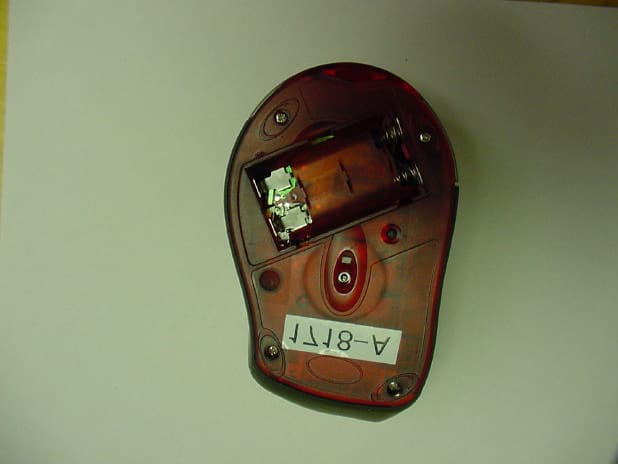
Click to zoom
Application Details
- Equipment Class
- DXX - Part 15 Low Power Communication Device Transmitter
- Date of Grant
- May 01, 2001
- Application Purpose
- Original Equipment
- Date of Application
- May 01, 2001
- Equipment Note
- Computer Wireless Pointing Device
- Frequency Range
- 27.04500000 - 27.14500000
- Company
- Microsoft Corporation
- Country
- United States
Documents & Files
Document Text
Text extracted from the exhibit documents filed with the FCC. Open a document above to read the original.
Users Manual
www.microsoft.com/mouse Getting Started with IntelliEye ® Optical Technology Wireless Pointing Devices Microsoft ® X08-13433_FCvr_Ret_Wireless IntelliMouse Explorer.p654/2/2001, 5:20 PM3 Wireless IntelliEye ® Pointing Devices About Your Rights and Obligations The software with this product is licensed, not sold. You must either agree to the license contract in the software Setup screens or promptly return the entire product for a refund, excluding the return costs. After you install the software, you may consult the license and the Limited Warranty for the product at any time by looking in the “Legal Information” section of the software User’s Guide. You may also print a copy for your records. Information in this document, including URL and other Internet Web site references, is subject to change without notice. Unless otherwise noted, the example companies, organizations, products, people and events depicted herein are fictitious and no association with any real company, organization, product, person or event is intended or should be inferred. Complying with all applicable copyright laws is the responsibility of the user. Without limiting the rights under copy- right, no part of this document may be reproduced, stored in or introduced into a retrieval system, or transmitted in any form or by any means (electronic, mechanical, photocopying, recording, or otherwise), or for any purpose, without the express written permission of Microsoft Corporation. Microsoft may have patents, patent applications, trademarks, copyrights, or other intellectual property rights covering subject matter in this document. Except as expressly provided in any written license agreement from Microsoft, the furnishing of this document does not give you any license to these patents, trademarks, copyrights, or other intellectual property. ©2001 Microsoft Corporation. All rights reserved. Patents pending Microsoft, Windows, Windows NT, IntelliEye, and IntelliMouse are either registered trademarks or trademarks of Microsoft Corporation in the United States and/or other countries. The names of actual companies and products mentioned herein may be the trademarks of their respective owners. 0501 Part No. X08-13433 Untitled-14/9/2001, 5:11 PM2 M 1 HEALTH WARNING Use of a keyboard or pointing device may be linked to serious injuries or disorders. When using a computer, as with many activities, you may experience occasional discomfort in your hands, arms, shoulders, neck, or other parts of your body. However, if you experience symptoms such as persistent or recurring discomfort, pain, throbbing, aching, tingling, numbness, burning sensation, or stiffness, DO NOT IGNORE THESE WARNING SIGNS. PROMPTLY SEE A QUALIFIED HEALTH PRO- FESSIONAL, even if symptoms occur when you are not working at your computer. Symptoms such as these can be associated with painful and sometimes permanently disabling injuries or disorders of the nerves, muscles, tendons, or other parts of the body. These musculoskeletal disorders (MSDs) include carpal tunnel syndrome, ten- donitis, tenosynovitis, and other conditions. While researchers are not yet able to answer many questions about MSDs, there is general agreement that many factors may be linked to their occurrence, including: medical and physical conditions, stress and how one copes with it, overall health, and how a person positions and uses his or her body during work and other activities (including use of a keyboard or pointing device). Some studies suggest that the amount of time a person uses a keyboard may also be a factor. Some guidelines that may help you work more comfortably with your computer and possibly reduce your risk of experiencing an MSD can be found in the “Healthy Computing Guide” topic of the User’s Guide, provided with the software program on your CD-ROM. If you do not have the CD-ROM for this product, you can access the “Healthy Computing Guide” from http://www.microsoft.com/hardware/, or (in the United States only) call 1-800-360-7561 to request a CD-ROM at no charge. If you have questions about how your own lifestyle, activities, or medical or physical condition may be related to MSDs, see a qualified health professional. Untitled-24/9/2001, 5:12 PM1 Wireless IntelliEye ® Pointing Devices 2 1 Welcome! Congratulations on your purchase of the finest wireless pointing device available—which includes the IntelliEye ® optical sensor for superior performance. Setting up the device takes just six simple steps, and then you can enjoy the freedom and convenience of wireless technology. Install IntInstall Int Install IntInstall Int Install Int elliPelliP elliPelliP elliP oint Sofoint Sof oint Sofoint Sof oint Sof twtw twtw tw areare areare are IntelliPoint software provides the drivers necessary to give your Microsoft wireless pointing device full functionality and displays battery status on the Windows ® taskbar. It also lets you customize the pointing device to fit your needs. For example, you can: •Reassign each of the buttons to perform a command or keyboard shortcut •Modify the pointing device settings, such as the pointer speed or wheel scrolling rate Note If you do not already have a pointing device connected, you can complete this step after you have connected the wireless receiver. This will allow you to complete the IntelliPoint Setup Wizard using a pointing device. TT TT T o install Into install Int o install Into install Int o install Int elliPelliP elliPelliP elliP oint sofoint sof oint sofoint sof oint sof twtw twtw tw are (Windoare (Windo are (Windoare (Windo are (Windo ws)ws) ws)ws) ws) 1Insert the Microsoft IntelliPoint compact disc into the computer’s CD-ROM drive. If the Setup Wizard does not appear automatically, do the following: •Click the Start button, and then click Run. •Type [drive]:setup. For example, if your CD-ROM drive is drive E, type e:setup. 2Follow the Setup Wizard instructions on the screen. 3When prompted, you must restart the computer before proceed…
Text truncated - open the document above for the full version.
Cover Letter(s)
American Telecommunications Certification Body Inc. 6731 Whittier Ave, McLean, VA 22101 April 26, 2001 RE: Microsoft Corporation FCC ID: C3KMS7 I have a couple of comments on this Application: 1.) Section 1.2 of the test report is an Expository Statement. The Letter of Confidentiality asks for the Expository Statement to be held confidential. Test reports can never be held confidential. Please resolve. 2.) FYI: The bold text in section 1.5 is awkward and misleading. In the future please clarify. 3.) Page 10 of 51 is blank – is this intentional? 4.) Product labeling in section 2.0 is unreadable. Label that was uploaded as separate exhibit is at best marginal. Please resubmit. 5.) Section 3.1 item 7 should read Receiver Channel 1 Local Oscillator 6.) Section 3.1 item 8 should read Receiver Channel 2 Local Oscillator 7.) Section 3.3 indicates, “ ...the end user is advised that to use the same type cables in this test report...” Are you suggesting the end user should be examining the report from the FCC website for information on cabling? How does this relate to a wireless peripheral? Shouldn’t information of this type be included in the manual? 8.) Speaking of manuals, none supplied with the Application. 9.) To insure compliance with band edges at 26.96 and 27.28 MHz, please supply occupied bandwidth plots for Ch 1 with CF of SA at 26.96 MHz, and for Ch 2 with CF of SA at 27.28 MHz. Use an RBW/VBW equal to 1% of modulated emission bandwidth. 10.) Please identify the RBW and VBW used for the peak and average measurements at the fundamental for Ch 1 and 2 11.) FYI: The 1.2MB Internal Photo file could be shrunk to ~388KB using the Acrobat Distiller. External Pics shrank to 132 KB. William H. Graff Examining Engineer President and Director of Engineering mailto:[email protected] The items indicated above must be submitted before processing can continue on the above referenced application. Failure to provide the requested information may result in application termination. Correspondence should be considered part of the permanent submission and may be viewed from the Internet after a Grant of Equipment Authorization is issued. Please do not respond to this correspondence using the email reply button. In order for your response to be processed expeditiously, you must submit your documents through the AmericanTCB.com website. Also, please note that partial responses increase processing time and should not be submitted. Any questions about the content of this correspondence should be directed to the sender.
External Photos
360 Herndon Parkway Suite 1400 Herndon, VA 20170 http://www.rheintech.com Page 27 of 51 Document Number: 2001078 Revision 2 6.0 EXTERNAL PHOTOS OF EUT FIGURE 3: Top of Mouse 360 Herndon Parkway Suite 1400 Herndon, VA 20170 http://www.rheintech.com Page 28 of 51 Document Number: 2001078 Revision 2 FIGURE 4: Bottom of Mouse 360 Herndon Parkway Suite 1400 Herndon, VA 20170 http://www.rheintech.com Page 29 of 51 Document Number: 2001078 Revision 2 FIGURE 5: Left Side of Mouse 360 Herndon Parkway Suite 1400 Herndon, VA 20170 http://www.rheintech.com Page 30 of 51 Document Number: 2001078 Revision 2 FIGURE 6: Right Side of Mouse 360 Herndon Parkway Suite 1400 Herndon, VA 20170 http://www.rheintech.com Page 31 of 51 Document Number: 2001078 Revision 2 FIGURE 7: Receiver With Cable 360 Herndon Parkway Suite 1400 Herndon, VA 20170 http://www.rheintech.com Page 32 of 51 Document Number: 2001078 Revision 2 FIGURE 8: Top of Receiver 360 Herndon Parkway Suite 1400 Herndon, VA 20170 http://www.rheintech.com Page 33 of 51 Document Number: 2001078 Revision 2 FIGURE 9: Bottom of Receiver 360 Herndon Parkway Suite 1400 Herndon, VA 20170 http://www.rheintech.com Page 34 of 51 Document Number: 2001078 Revision 2 FIGURE 10: Front of Receiver
Internal Photos
360 Herndon Parkway Suite 1400 Herndon, VA 20170 http://www.rheintech.com Page 35 of 51 Document Number: 2001078 Revision 2 7.0 INTERNAL PHOTOS OF EUT FIGURE 11: Inside Plastic Bezel 360 Herndon Parkway Suite 1400 Herndon, VA 20170 http://www.rheintech.com Page 36 of 51 Document Number: 2001078 Revision 2 FIGURE 12 : Bottom of Plastic Bezel 360 Herndon Parkway Suite 1400 Herndon, VA 20170 http://www.rheintech.com Page 37 of 51 Document Number: 2001078 Revision 2 FIGURE 13 : Top of Plastic Bezel 360 Herndon Parkway Suite 1400 Herndon, VA 20170 http://www.rheintech.com Page 38 of 51 Document Number: 2001078 Revision 2 FIGURE 14 : Top of Plastic Bezel with PCB Boards 360 Herndon Parkway Suite 1400 Herndon, VA 20170 http://www.rheintech.com Page 39 of 51 Document Number: 2001078 Revision 2 FIGURE 15 : Top of Plastic Bezel with One PCB Board 360 Herndon Parkway Suite 1400 Herndon, VA 20170 http://www.rheintech.com Page 40 of 51 Document Number: 2001078 Revision 2 FIGURE 16 : Component Side of the Tracker PCB Board 360 Herndon Parkway Suite 1400 Herndon, VA 20170 http://www.rheintech.com Page 41 of 51 Document Number: 2001078 Revision 2 FIGURE 17 : Solder Side of the Tracker PCB Board 360 Herndon Parkway Suite 1400 Herndon, VA 20170 http://www.rheintech.com Page 42 of 51 Document Number: 2001078 Revision 2 FIGURE 18 : Component Side of the Optic PCB Board 360 Herndon Parkway Suite 1400 Herndon, VA 20170 http://www.rheintech.com Page 43 of 51 Document Number: 2001078 Revision 2 FIGURE 19 : Solder Side of the Optic PCB Board 360 Herndon Parkway Suite 1400 Herndon, VA 20170 http://www.rheintech.com Page 44 of 51 Document Number: 2001078 Revision 2 FIGURE 20 : Solder Side of the Optic PCB Board without Lens 360 Herndon Parkway Suite 1400 Herndon, VA 20170 http://www.rheintech.com Page 45 of 51 Document Number: 2001078 Revision 2 FIGURE 21 : Top of Main PCB Board 360 Herndon Parkway Suite 1400 Herndon, VA 20170 http://www.rheintech.com Page 46 of 51 Document Number: 2001078 Revision 2 FIGURE 22 : Bottom of Main PCB Board 360 Herndon Parkway Suite 1400 Herndon, VA 20170 http://www.rheintech.com Page 47 of 51 Document Number: 2001078 Revision 2 FIGURE 23 : Inside Top of Receiver Bezel 360 Herndon Parkway Suite 1400 Herndon, VA 20170 http://www.rheintech.com Page 48 of 51 Document Number: 2001078 Revision 2 FIGURE 24 : Inside Bottom of Receiver Bezel 360 Herndon Parkway Suite 1400 Herndon, VA 20170 http://www.rheintech.com Page 49 of 51 Document Number: 2001078 Revision 2 FIGURE 25 : Component Side of Receiver PCB 360 Herndon Parkway Suite 1400 Herndon, VA 20170 http://www.rheintech.com Page 50 of 51 Document Number: 2001078 Revision 2 FIGURE 26 : Solder Side of Receiver PCB
Operational Description
Microsoft Confidential Microsoft Wireless IntelliMouse® Explorer™ FCC ID: C3KMS7 Microsoft Wireless IntelliMouse Explorer: Expository Statement Grantee: Microsoft Corporation FCC ID: C3KMS7 Model: Microsoft Wireless IntelliMouse® Explorer™ The Microsoft Wireless IntelliMouse® Explorer™ is a computer input device typically used for both cursor positioning on the computer's video display screen and also for scrolling through and magnification of application documents. Refer to Microsoft Wireless IntelliMouse Explorer: Block diagrams, for the following description. When a user moves the mouse enclosure on a flat surface, the circuitry within the mouse detects this motion and translates it into a form usable by the host computer to move the cursor. When the user moves the wheel on the top of the device, the circuitry within the mouse detects this motion and translates it into a form usable by the host computer to scroll through and magnify application documents. Additionally, the mouse contains five push button switches, which can be actuated at the user's discretion to generate an asynchronous event, typically used to alter the program's control flow in the host computer. In the Wireless IntelliMouse® Explorer, a solid-state tracking engine illuminates the surface with a visible spectrum LED. The solid-state tracking engine takes many samples per second on an imaging array. Using a built in Signal Processor, consecutive images are compared to determine physical displacement (motion). The displacement information is transmitted to a second controller that also decodes button and wheel activity. This second controller handles all communication with the receiver unit though an RF communication path. The motion data, button status information, and wheel information is encoded using a proprietary digital coding system and clocked out of the controller as a serial data stream. The transmitter operates on one of the two available channels, at either 27.045MHz (Channel 1) or 27.145MHz (Channel 2). The channel is selected by switching the local oscillator crystals (13.522MHz for Channel 1 and 13.572MHz for Channel 2). The transmitter uses Frequency Shift Keying (FSK) modulation, and consists of a crystal- controlled FSK modulator, a frequency doubler, and an output driver. The effective radiated power of the transmitter is less than 5μW. To save the batteries, the controller switches ON the transmitter only in the active state of the mouse. The active state continues about 2 seconds after the last movement or button press; then the mouse goes in the sleep active state or sleep touch state (depending upon whether the touch sense line is active). During the sleep state, the controller samples the optical drivers and detectors and the buttons to detect any movement or button press. If any activity is detected, the mouse goes back to the active state. DC-power is obtained from two AA batteries. The mouse uses a double-sided printed circuit board and a trace running in a loop on the printed circuit board to act as the antenna. The receiver provides the facility to communicate with a host computer as a USB device. The receiver is connected to a host computer using a four-wire cable. Two of these four wires are Power and Ground. The remaining two wires are used for bi-directional signaling. The four-wire cable is shielded, with a ferrite bead at the connector end, and is approximately 1.52 meters in length. The host end terminates in a 4- pin USB Series A Receptacle Interface connector. The receiver is a single conversion type. The local oscillator is a crystal-controlled oscillator operating at either 26.59MHz (Channel 1) or 26.69MHz (Channel 2). Consequently, an intermediate frequency of 455 kHz is obtained after the mixer. The modulating signal is recovered from the IF by a quadrature detector, and then converted to digital form. A single chip controller, operating at a clock frequency of 6MHz, decodes the received data and controls the USB interface to the PC using the USB protocol. Power is obtained from the host computer (5 volts, regulated) through a permanently attached cable. The receiver uses a trace running in a loop on the printed circuit board to act as the antenna.
Test Report
EMC COMPLIANCE ENGINEERING AND TESTING Accredited 360 Herndon Parkway, Suite 1400 Herndon,VA 20170 703 689-0368 FAX 703 689-2056 APPLICATION FOR FCC CERTIFICATION CLASS B TRANSMITTER DEVICE Microsoft Corporation 1 Microsoft Way Redmond, WA 98052 425-882-8080 MODEL: Wireless IntelliMouse Explorer and Wireless IntelliMouse Explorer 1.0A FCC ID: C3KMS7 April 9, 2001 REPORT PREPARED BY: EMI Technician: Elizabeth Szrajer Rhein Tech Laboratories, Inc. Document Number: 2001078 No part of this report may be reproduced without the full written approval of Rhein Tech Laboratories, Inc. This report concerns (check one): Original Grant: X Class II Change: Equipment Type: Transmitter Deferred grant requested per 47 CFR 0.457 (d) (1) (ii)? Yes: No: X If yes, defer until: Date Company name agrees to notify the Commission by: (date) of the intended date of announcement of the product so that the grant can be issued on that date. 360 Herndon Parkway Suite 1400 Herndon, VA 20170 http://www.rheintech.com Page 2 of 51 Document Number: 2001078 Revision 3 TABLE OF CONTENTS 1.0 GENERAL INFORMATION..................................................................................................................4 1.1 RELATED SUBMITTAL(S)/GRANT(S)/DOC(S)....................................................................................4 1.2 PRODUCT DESCRIPTION...............................................................................................................................5 1.3 TEST SYSTEM DETAILS................................................................................................................................6 1.4 CONFIGURATION OF TESTED SYSTEM......................................................................................................7 1.5 TEST METHODOLOGY...................................................................................................................................8 1.6 TEST FACILITY...............................................................................................................................................8 2.0 PRODUCT LABELING............................................................................................................................9 3.0 SYSTEM TEST CONFIGURATION................................................................................................10 3.1 JUSTIFICATION.............................................................................................................................................10 3.2 EUT EXERCISE SOFTWARE.......................................................................................................................10 3.3 SPECIAL ACCESSORIES...............................................................................................................................11 3.5 CONFORMANCE STATEMENT................................................................................................................11 4.0 MEASUREMENT PHOTOS................................................................................................................17 5.0 RADIATED EMISSION DATA...........................................................................................................18 5.1 FIELD STRENGTH CALCULATION........................................................................................................22 6.0 20DB BANDWIDTH DATA..................................................................................................................23 7.0 BAND EDGE DATA.................................................................................................................................25 8.0 EXTERNAL PHOTOS OF EUT.........................................................................................................27 9.0 INTERNAL PHOTOS OF EUT..........................................................................................................35 APPENDIX LISTING APPENDIX A: SCHEMATICS OF MICROSOFT WIRELESS INTELLIMOUSE EXPLORER (CONFIDENTIAL)12 APPENDIX B: BLOCK DIAGRAM OF MICROSOFT WIRELESS INTELLIMOUSE EXPLORER (CONFIDENTIAL).......................................................................................................................................................15 APPENDIX C: EMISSIONS EQUIPMENT LIST................................................................................................................51 APPENDIX D: CONDUCTED AND RADIATED TEST METHODOLOGY..............................................................................53 APPENDIX E: USER’S MANUAL.................................................................................................................................55 360 Herndon Parkway Suite 1400 Herndon, VA 20170 http://www.rheintech.com Page 3 of 51 Document Number: 2001078 Revision 3 FIGURE INDEX FIGURE 1: FCC LABEL STATEMENT IN MICROSOFT MANUAL ON PAGE 3..................................................................9 FIGURE 2: LOCATION AND LABEL SAMPLE ON EUT...................................................................................................9 FIGURE 3: TOP OF MOUSE.........................................................................................................................................27 FIGURE 4: BOTTOM OF MOUSE.................................................................................................................................28 FIGURE 5: LEFT SIDE OF MOUSE...............................................................................................................................29 FIGURE 6: RIGHT SIDE OF MOUSE.............................................................................................................................30 FIGURE 7: RECEIVER WITH CABLE............................................................................................................................31 FIGURE 8: TOP OF RECEIVER.................…
Text truncated - open the document above for the full version.
Test Setup Photos
360 Herndon Parkway Suite 1400 Herndon, VA 20170 http://www.rheintech.com Page 20 of 51 Document Number: 2001078 Revision 2 4.0 MEASUREMENT PHOTOS 4.1 RADIATED MEASUREMENT PHOTOS 360 Herndon Parkway Suite 1400 Herndon, VA 20170 http://www.rheintech.com Page 21 of 51 Document Number: 2001078 Revision 2
Contact Information
Applicant
Hasnain Syed(SR. DIR EMC/SI&RF COMPLIANCE)
Technical Contact
Rhein Tech Laboratories, Inc.Elizabeth Szrajer
[email protected]703 689 0368
360 Herndon Parkway · Herndon, Virginia · United States
Test Firm
Rhein Tech Laboratories, Inc.Rick McMurray
Technical Specifications
| # | Rule Parts | Frequency Range | Power Output |
|---|---|---|---|
| 1 | 15C | 27.045 MHz - 27.145 MHz | - |
Other Applications from Microsoft Corporation
C3K2147
Aug 28, 2026Wireless input device
Equipment Class
DTS - Digital Transmission SystemC3K2148
Aug 12, 2026Portable Computing Device
Equipment Class
DXX - Part 15 Low Power Communication Device TransmitterC3K2149
Aug 12, 2026Portable Computing Device
Equipment Class
DXX - Part 15 Low Power Communication Device TransmitterC3K2152
Aug 11, 2026Wireless Accessory
Equipment Class
DTS - Digital Transmission SystemC3K2150
Aug 06, 2026Portable Computing Device
Equipment Class
DXX - Part 15 Low Power Communication Device Transmitter