C3KTR1Wireless USB Transceiver
Microsoft Corporation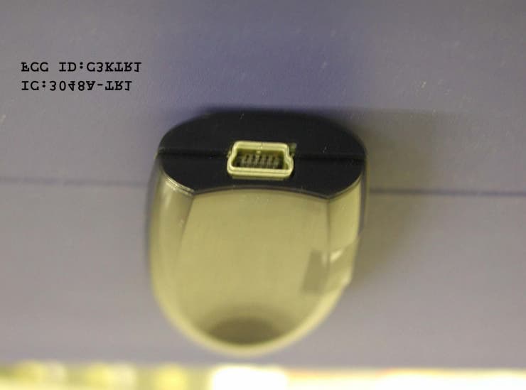
Click to zoom
Application Details
- Equipment Class
- DSS - Part 15 Spread Spectrum Transmitter
- Date of Grant
- Sep 13, 2002
- Application Purpose
- Original Equipment
- Date of Application
- Sep 13, 2002
- Equipment Note
- Wireless USB Transceiver
- Frequency Range
- 2402.00000000 - 2480.00000000
- Company
- Microsoft Corporation
- Country
- United States
Documents & Files
Document Text
Text extracted from the exhibit documents filed with the FCC. Open a document above to read the original.
Users Manual
C3KTR1 Manual Please note that the Lapis Dongle in this manual is referred to as the “Wireless Transceiver for Bluetooth”. M www.microsoft.com/keyboard Microsoft ® Keyboard and Mouse Suites with Bluetooth ™ Wireless Technology Getting Started Health Warning Use of a keyboard or pointing device may be linked to serious injuries or disorders. When using a computer, as with many activities, you may experience occasional discomfort in your hands, arms, shoul- ders, neck, or other parts of your body. However, if you experience symptoms such as persistent or recurring discomfort, pain, throbbing, aching, tingling, numbness, burning sensation, or stiffness, DO NOT IGNORE THESE WARNING SIGNS. PROMPTLY SEE A QUALIFIED HEALTH PROFESSIONAL, even if symptoms occur when you are not working at your com- puter. Symptoms such as these can be associated with painful and sometimes permanently disabling injuries or disorders of the nerves, muscles, tendons, or other parts of the body. These musculoskeletal disorders (MSDs) include carpal tun- nel syndrome, tendonitis, tenosynovitis, and other conditions. While researchers are not yet able to answer many questions about MSDs, there is general agreement that many factors may be linked to their occurrence, including: medical and physical conditions, stress and how one copes with it, overall health, and how a person positions and uses his or her body during work and other activities (including use of a keyboard or pointing device). Some studies suggest that the amount of time a person uses a keyboard may also be a factor. Some guidelines that may help you work more comfortably with your computer and possibly reduce your risk of experiencing an MSD can be found in the “Healthy Computing Guide” topic of the User’s Guide provided with each software program on your CD-ROM. If you do not have the CD-ROM for this product, you can access the “Healthy Computing Guide” at http://www.microsoft.com/hardware/, or (in the United States only) call 1-800-360-7561 to request a CD-ROM at no charge. If you have questions about how your own lifestyle, activities, or medical or physical condition may be related to MSDs, see a qualified health professional. About Your Rights and Obligations This Microsoft ® wireless suite is comprised of a keyboard, mouse, and receiver and is sold as a single unit and may not be separated for use on more than one computer. The software with this product is licensed, not sold. You must either agree to the license contract in the software Setup screens or promptly return the Microsoft wireless suite, comprised of the keyboard, mouse, and receiver, along with the software, for a refund, excluding the return costs. After you install the software, you may consult the license and the Limited Warranty for the product at any time by looking in the “Legal Information” section of the software User’s Guides. You may also print a copy for your records. Information in this document, including URL and other Internet Web site references, is subject to change without notice. Unless otherwise noted, the example companies, organizations, products, domain names, e-mail addresses, logos, people, places and events depicted herein are fictitious, and no association with any real company, organization, product, domain name, e-mail address, logo, person, place or event is intended or should be inferred. Complying with all applicable copyright laws is the responsibility of the user. Without limiting the rights under copyright, no part of this document may be reproduced, stored in or introduced into a retrieval system, or transmitted in any form or by any means (electronic, mechanical, photocopying, recording, or otherwise), or for any purpose, without the express written permission of Microsoft Corporation. Microsoft may have patents, patent applications, trademarks, copyrights, or other intellectual property rights covering subject matter in this document. Except as expressly provided in any written license agreement from Microsoft, the furnishing of this document does not give you any license to these patents, trademarks, copyrights, or other intellectual property. Microsoft Corporation grants the purchaser of this product the right to reproduce one (1) copy of this “Getting Started” printed guide for each Hardware Suite you purchased in the package. ©2002 Microsoft Corporation. All rights reserved. Microsoft, IntelliMouse, Natural, and Windows are either registered trademarks or trademarks of Microsoft Corporation in the United States and/or other countries. The names of actual companies and products mentioned herein may be the trademarks of their respective owners. 1 Welcome Congratulations on your purchase of a Microsoft ® keyboard and mouse suite with Bluetooth™ wireless technology. This complete desktop solution includes a wireless keyboard, a wireless mouse, and a Wireless Transceiver. Setting up the devices takes a few simple steps, and then you can enjoy the freedom of Bluetooth wireless technology and the convenience of a clutter-free desktop. Run the Setup Wizard First The Setup Wizard installs the required software and helps you set up your Bluetooth devices. Important •You must leave your current keyboard and mouse connected in order to complete Setup. •Make sure you run the installation CD-ROM that has the same software language as your operating system. To run the Setup Wizard 1Insert the software installation CD-ROM that contains your operating system language into the computer’s CD-ROM drive. If the Setup screen does not appear automatically, do the following: •Click the Start button, and then click Run. •Type [drive]:setup. For example, if your CD-ROM drive is drive E, type e:setup 2Click Install Microsoft IntelliType Pro to begin the keyboard software installation. Follow the Setup Wizard instructions on the screen. Depending on the Bluetooth software components your system requires, you may be prompted to restart your computer during software installa…
Text truncated - open the document above for the full version.
Cover Letter(s)
Microsoft Corporation Tel: 425 882 8080 One Microsoft Way Fax: 425 936 7329 Redmond, WA 98052-6399 http://www.microsoft.com/ August 8, 2002 Federal Communications Commission Authorization and Evaluation Division 7435 Oakland Mills Road Columbia, Maryland 21046 To whom it may concern, We hereby respectfully request that under the provision of 47 CFR 0.459, the documents listed below and attached with this application for certification for FCC ID: C3KKB11, C3KMS10 and C3KTR1 be provided with confidential status. • Schematics • Block Diagrams • Bill of Materials Any exhibit / information for which we have requested confidentiality, but which may not be accorded such treatment by the FCC, should be returned to us. The documents listed above contain trade secrets that are treated as confidential by us. Substantial competitive harm to us could result should they be made available to the public. Sincerely, Stephen Stegner EMC/Safety Engineer Microsoft Corporation
Cover Letter(s)
Dt Associates PO Box 1644 Mariposa, CA Phone: 209 966-2145 Email: [email protected] CONSULTING SERVICES FOR REGULATORY APPROVALS – STANDARDS APPLICATION – COMMERCIAL •• INDUSTRIAL •• MEDICAL EMC •• Dt Associates – PO Box 1644, Mariposa, CA 95338 – phone: (209) 966-2145 email: [email protected] August 8, 2002 Response to ATCB request Dear Tim. The following is a response to your request for information. 1: a) clearer external photographs. Respons: A clearer external photograh has been requested and will be uploaded within the next day or two b) a photograph of the back of the Bluetooth module. Response: A photograph of the back of the Bluetooth module has been requested of the lab. Please note however, that this is a soldered board level component similar to a CPU chip on the EUT. Also, since there is nothing on the bottom side of this component, I have provided the master layout masks of this module and the board on which it resides. Please accept this in lieu of de-soldering the component. c) a photograph of the main board with the Bluetooth module removed. Response: Please note that the device in question is soldered to the main board as a component at the factory. In lieu of the possibly destructive nature of de-soldering the Bluetooth modular component for photographing, I have attached the master layout drawing of the dongle main board showing the compnonet locations and traces under the Bluetooth modular component. Please accept this as evidence in accordance with 2.1033b7 requirements of defining component location and construction properties. These layout drawings are not listed in the confidentialiality request. 2) Regarding the Transmitter Schematics, please provide one of the following: Response: I have requested the information from the manufacturer. However, please note that the Bluetooth ‘modular’ section is treated as a component in this system. The schematics of the ‘transmitter’ show this modular component as it is used in the system with input and output information. This is in the same manner as other chips or components are shown. Please note that the master layout mask shows the Bluetooth board-component part number. The product is an OEM product and I have requested the part number from Microsoft and should have it shortly. While Parts Lists are not required for Part 15 devices, please accept this as meeting your request for verification that this is a component of the EUT. CONSULTING SERVICES FOR REGULATORY APPROVALS – STANDARDS APPLICATION – COMMERCIAL •• INDUSTRIAL •• MEDICAL EMC •• Dt Associates – PO Box 1644, Mariposa, CA 95338 – phone: (209) 966-2145 email: [email protected] 3) and 4) The EUT is considered a PC peripheral device + transmitter and is subject to the applicable requirements of both. However to meet all the applicable requirements for this device it should also be certified under the same ID number as a PC peripheral or it should be tested by an accredited laboratory as a PC peripheral. The test report provided for certification appears to only cover the transceiver portion of the device. Please note that when tested as a PC peripheral, the device should be configuration as specified by ANSI C63.4 Section 11. The minimum configuration specified includes 2 additional interface ports (i.e. parallel and serial) in addition to the monitor, keyboard, mouse ports which did not appear to be filled. Please confirm that the EUT has been properly evaluated and tested by an accredited laboratory for DoC requirements as a PC peripheral device or provide a copy of the DoC report. Also, please note that the FCC's web site does not appear to list Taiyo Yuden as an accredited test lab. Assuming the device has been tested for a DoC authorization as a PC peripheral device, the label should also include the appropriate Part 15 DoC labeling information. Please provide a corrected exhibit. Response: Taiyo Yuden is listed with the FCC. You will find them as Taiyo Yuden Co., Ltd. Please check again. The device label showing the FCC DoC will be provided. As such, the label itself is evidence of compliance and as such, no test data for digital deivce peripherals will be necessary. The label and attestation has been requested and will be provided shortly. 5)The compliance information sheet (either separate sheet or information contained on a single page within the manual as specified by 2.1077) is required for DoC authorizations. Most of this information required by 2.1077 is located on page 5 of the users manual. However the compliance information on this page should also contain the following information: a) The identification, by name, address and telephone number, of the responsible party. The responsible party is defined as either the manufacturer, or if the equipment is imported, the importer. The responsible party for a Declaration of Conformity must be located within the United States. Response: I have requested the information to be provided. 6) RF exposure statement. Response: I have provided a copy of the email between Microsoft and the FCC on rf exposure statements for these devices. Please accept this email as evidence that the suggested or similar wording that appears in the manuals is appropriate. Please note that the FCC has stated that no specific caution language is mandated. As such, any reasonable wording with the intent of cautioning or giving instructions to the user about rf exposure should be deemed appropriate. Because of the response of the FCC and since the MPE calculations show the device compliant at less than 0.3cm we request that accept the wording as provided and as ‘de-facto’ approved by the FCC in their email response. CONSULTING SERVICES FOR REGULATORY APPROVALS – STANDARDS APPLICATION – COMMERCIAL •• INDUSTRIAL •• MEDICAL EMC •• Dt Associates – PO Box 1644, Mariposa, CA 95338 – phone: (209) 966-2145 email: [email protected] 7) And 8) In the Antenna Conducted report, please explain section 5.5 where it mentions the devices was tes…
Text truncated - open the document above for the full version.
Cover Letter(s)
American Telecommunications Certification Body Inc. 6731 Whittier Ave, McLean, VA 22101 August 7, 2002 RE: Microsoft Corporation FCC ID: C3KTR1 After a review of the submitted information, I have a few comments on the above referenced Application. 1) Please provide: a) clearer external photographs b) a photograph of the back of the Bluetooth module. c) a photograph of the main board with the Bluetooth module removed. 2) Regarding the Transmitter Schematics, please provide one of the following: a) A schematic of the RF portion (Bluetooth Module). b) Alternatively, if the radio is a modular component from a different manufacturer, you may instead provide a parts list that shows the Bluetooth Module as a part from a different manufacturer. If the parts list is provided, please be sure to let us know if confidentiality is requested on it and update the confidentiality letter if necessary. 3) The EUT is considered a PC peripheral device + transmitter and is subject to the applicable requirements of both. However to meet all the applicable requirements for this device it should also be certified under the same ID number as a PC peripheral or it should be tested by an accredited laboratory as a PC peripheral. The test report provided for certification appears to only cover the transceiver portion of the device. Please note that when tested as a PC peripheral, the device should be configuration as specified by ANSI C63.4 Section 11. The minimum configuration specified includes 2 additional interface ports (i.e. parallel and serial) in addition to the monitor, keyboard, mouse ports which did not appear to be filled. Please confirm that the EUT has been properly evaluated and tested by an accredited laboratory for DoC requirements as a PC peripheral device or provide a copy of the DoC report. Also, please note that the FCC's web site does not appear to list Taiyo Yuden as an accredited test lab. 4) Assuming the device has been tested for a DoC authorization as a PC peripheral device, the label should also include the appropriate Part 15 DoC labeling information. Please provide a corrected exhibit. 5) The compliance information sheet (either separate sheet or information contained on a single page within the manual as specified by 2.1077) is required for DoC authorizations. Most of this information required by 2.1077 is located on page 5 of the users manual. However the compliance information on this page should also contain the following information: a) The identification, by name, address and telephone number, of the responsible party. The responsible party is defined as either the manufacturer, or if the equipment is imported, the importer. The responsible party for a Declaration of Conformity must be located within the United States. 6) Assuming the keyboard, mouse, and transceiver are all classified as mobile devices for RF exposure purposes, the users manual should contain the following RF exposure information or similar: " The antenna(s) used for this transmitter must be installed to provide a separation distance of at least 20 cm from all persons and must not be co-located or operating in conjunction with any other antenna or transmitter." 7) In the Antenna Conducted report, please explain section 5.5 where it mentions the devices was tested using a fully charged battery. This device does not appear to contain a battery. Please explain. 8) In the Antenna Conducted report, section 5.6 states the device was tested as a stand-alone configuration which is representative of typical use. Please explain as the EUT is a USB Dongle expected to be attached to a computer. 9) FYI, the table 6.1.3 of the Antenna Conducted report contains an incorrect data. z Page 2August 7, 2002 10) The radiated spurious emissions report did not contain 3 sets of data for a typical low, middle and high channel, or contain information to clearly define if the data table provided encompasses all 3 test frequencies. Please explain or provide the missing test data. Note that section 4 also references Annex A, which does not appear to be provided. 11) Section 6 of the radiated emissions report shows ferrite cores on the AC line cord, keyboard, mouse, and CRT. Section 3.4 shows that ferrite were not on the AC line cord. The test system should contain a minimum number of ferrites. Please confirm if the ferrite was present on the AC line cord. 12) The EUT obtains its power from a host computer. Please provide conducted emissions that show compliance with 15.207. Timothy R. Johnson Examining Engineer mailto: [email protected] The items indicated above must be submitted before processing can continue on the above referenced application. Failure to provide the requested information may result in application termination. Correspondence should be considered part of the permanent submission and may be viewed from the Internet after a Grant of Equipment Authorization is issued. Please do not respond to this correspondence using the email reply button. In order for your response to be processed expeditiously, you must submit your documents through the AmericanTCB.com website. Also, please note that partial responses increase processing time and should not be submitted. Any questions about the content of this correspondence should be directed to the sender.
Cover Letter(s)
American Telecommunications Certification Body Inc. 6731 Whittier Ave, McLean, VA 22101 August 9, 2002 RE: Microsoft Corporation FCC ID: C3KTR1 After a review of the submitted information, I have a few additional comments on the above referenced Application. 1) Taiyo Yuden test site is listed with the FCC as required for 2.948. However the FCC site does not show Taiyo Yuden listed as an Accredited test lab as required to perform testing for DoC authorizations. 2) The FCC has required testing of frequency hopping systems to be hop-stopped for tests such as the spurious emissions unless the manufacturer can not provide this mode of operation (see attached document, section 15.31(m)). The purpose behind this is to ensure that the emissions can be adequately captured given that when a unit is typically hopping the results will depend on the hopping speed, spectrum analyzer sweep times, spectrum analyzer span, and maximizing the azimuth and antenna height. Without a "hop-stopped" signal, obtaining fully maximized results for azimuth and antenna height is incredibly time consuming (given the spectrum analyzer sweep times or capture times necessary to maximize the signals) and can still yield questionable results. Please note that the sweep time can significantly affect how the measurements are captured or whether they are missed. Also with wider spans, dynamic range gets reduced and spectrum analyzer may not accurately capture and or display the emissions. Testing while the device is hopping also questions how the devices was fully maximized for azimuth and antenna height given the difficult nature of obtaining data at any given point. Please provide a) new results/plots with the hopping function disabled for low, middle, and high channels, or b) If the manufacturer can not provide a hop stopped mode of operation, then please explain why and provide better supporting detail regarding how the device was fully maximized (spectrum analyzer settings and how care was taken to obtain maximum azimuth and antenna height given the difficulty in fully capturing highest emissions across the band during hopping) when the results were obtained. 3) You stated that the unit may derive its power from an already approved host. 15.207(d) requires "Devices that include, or make provisions for .......... obtaining their power through another device which is connected to the AC power lines, shall be tested to demonstrate compliance with the conducted limits". The FCC does not require to test all possible configurations of PC's and peripherals as this would not be practical. However they do require you to test for the known configuration (if this exists), or if a known configuration does not exist to test using a single typical configuration. Please note that we have seen the cases where the approved hosts conducted emissions vary (pass vs. fail) due to the peripheral(s) attached. 4) FYI, we are still awaiting certain items as specified in your last reply. Timothy R. Johnson Examining Engineer mailto: [email protected] The items indicated above must be submitted before processing can continue on the above referenced application. Failure to provide the requested information may result in application termination. Correspondence should be considered part of the permanent submission and may be viewed from the Internet after a Grant of Equipment Authorization is issued. Please do not respond to this correspondence using the email reply button. In order for your response to be processed expeditiously, you must submit your documents through the AmericanTCB.com website. Also, please note that partial responses increase processing time and should not be submitted. z Page 2August 9, 2002 Any questions about the content of this correspondence should be directed to the sender.
Cover Letter(s)
American Telecommunications Certification Body Inc. 6731 Whittier Ave, McLean, VA 22101 September 12, 2002 RE: Microsoft Corporation FCC ID: C3KTR1 After a review of the submitted information, I have a few comments on the above referenced Application. EMC Issue 1) Hyper Corp. is not listed as a test site with the FCC. The test report states that the device was tested at UL while the 731 form provided lists information for CCS. Please confirm that the testing for this was performed at UL. Outstanding Transmitter Issue 2) The FCC has required testing of frequency hopping systems to be hop-stopped for tests such as the spurious emissions unless the manufacturer can not provide this mode of operation (see attached document, section 15.31(m)). The purpose behind this is to ensure that the emissions can be adequately captured given that when a unit is typically hopping the results will depend on the hopping speed, spectrum analyzer sweep times, spectrum analyzer span, and maximizing the azimuth and antenna height. Without a "hop-stopped" signal, obtaining fully maximized results for azimuth and antenna height is incredibly time consuming (given the spectrum analyzer sweep times or capture times necessary to maximize the signals) and can still yield questionable results. Please note that the sweep time can significantly affect how the measurements are captured or whether they are missed. Also with wider spans, dynamic range gets reduced and spectrum analyzer may not accurately capture and or display the emissions. Testing while the device is hopping also questions how the devices was fully maximized for azimuth and antenna height given the difficult nature of obtaining data at any given point. Please provide a) new results/plots with the hopping function disabled for low, middle, and high channels, or b) If the manufacturer can not provide a hop stopped mode of operation, then please explain why and provide better supporting detail regarding how the device was fully maximized (spectrum analyzer settings and how care was taken to obtain maximum azimuth and antenna height given the difficulty in fully capturing highest emissions across the band during hopping) when the results were obtained. Timothy R. Johnson Examining Engineer mailto: [email protected] The items indicated above must be submitted before processing can continue on the above referenced application. Failure to provide the requested information may result in application termination. Correspondence should be considered part of the permanent submission and may be viewed from the Internet after a Grant of Equipment Authorization is issued. Please do not respond to this correspondence using the email reply button. In order for your response to be processed expeditiously, you must submit your documents through the AmericanTCB.com website. Also, please note that partial responses increase processing time and should not be submitted. Any questions about the content of this correspondence should be directed to the sender.
Cover Letter(s)
September 18, 2002 Amer ican Telecommunicat ions Cert if icat ion Body 6731 Whittier Avenue McLean, VA 22101 Dear Sirs: This letter of attestation is to address the EMC and Outstanding Transmitter Issues address in the September 12, 2002 letter regarding the certification FCC ID: C3KTR1. Issue 1 – Hyper Corporation attests that the laboratory that w as used for testing the device for the computer peripheral certification (Subpart B – Uni ntentional Radiators) w as performed at the Underwriters Laboratory located at 11825 Niles Canyon Road in Sunol, CA. This laboratory should be the laboratory of record for the certification of the device (computer peripheral). Issue 2 – Hyper Corporation attests that the transmitter testing that was performed at Taiyo Y uden w as tested with the frequency hopping stopped at the low, middle, and high channels for testing emissions from the device. Emissions w ere maximized at each channel following the procedures in ANSI C63.4. The data reported on pages 18-21 of the report is a compilation of the data taken w ith the hopping stopped at the low, middle, and high channels and is the w ay the report w as generated. Plots show ing each individual channel are not readily available at this time and would cause significant expense to produce. Sincerely, William Elliott Staff Engineer – Wireless Testing Hyper Corpor at ion Phone: 1-925-462-9105 ext. 208 Email: [email protected] 1279 Quarry Lane Pleasanton, California 94566-8499
External Photos
Exhibit 5 External Photos Lapis Dongle C3KTR1
ID Label/Location Info
Exhibit 6 Label Information Lapis Dongle C3KTR1
Internal Photos
Exhibit 7 Internal Photos C3KTR1 Lapis Dongle
Internal Photos
CAM350 PRO V 7.0 : Fri May 10 13:51:22 2002 - (Untitled) : Topcop CAM350 PRO V 7.0 : Fri May 10 13:51:22 2002 - (Untitled) : ground CAM350 PRO V 7.0 : Fri May 10 13:51:23 2002 - (Untitled) : power CAM350 PRO V 7.0 : Fri May 10 13:51:23 2002 - (Untitled) : botcop CAM350 PRO V 7.0 : Fri May 10 13:51:24 2002 - (Untitled) : topmask CAM350 PRO V 7.0 : Fri May 10 13:51:24 2002 - (Untitled) : botmask CAM350 PRO V 7.0 : Fri May 10 13:51:24 2002 - (Untitled) : toppaste CAM350 PRO V 7.0 : Fri May 10 13:51:24 2002 - (Untitled) : topsilk CAM350 PRO V 7.0 : Fri May 10 13:51:24 2002 - (Untitled) : board CAM350 PRO V 7.0 : Fri May 10 13:51:25 2002 - (Untitled) : topassy CAM350 PRO V 7.0 : Fri May 10 13:51:25 2002 - (Untitled) : PinFunctions
Operational Description
BlueCore 2-External Product Data Sheet TM BC212015-ds-001b Product Data Sheet Pre-Production Information Single Chip Bluetooth System Pre-Production Information Data Sheet BC212013A (UART only version) BC212015A (USB and UART version) October 2001 BlueCore2-External is a single chip radio and baseband IC for Bluetooth 2.4GHz radios implemented in CMOS technology. When used with external ROM containing the CSR Bluetooth software stack, it provides a fully compliant Bluetooth system for data and voice communications. General Description Figure 1:BlueCore2-External System Architecture RAM DSP μP I/O 2.4 GHz Radio XTAL SPI UART/USB PIO PCM 8Mbit FLASH ROM RF IN RF OUT BlueCore 2-External TM Applications The design is optimised to require few external RF components to facilitate rapid design of the application printed circuit board and therefore the fastest possible time to market and lowest overall cost. Included in the device are autocalibration and built-in- self-test (BIST) routines to simplify development, type approval and production test. All hardware and device firmware is fully compliant with the Bluetooth specification. Device Features Low power 1.8V operation Small footprint in 96-Ball VFBGA Package (6x6mm) Fully qualified Bluetooth component 0.18μm CMOS technology Full speed class 2 Bluetooth operation with full 7 slave piconet support Support for 8Mbit external Flash Minimum external components Operates over full industrial temperature range (-40 ≤≤ T ≤≤ 105∞C) PC Notebooks Cellular Handsets Cordless Headsets Personal Digital Assistants (PDAs) Computer Accessories (Compact Flash, PCMCIA and SD cards) BlueCore 2-External Product Data Sheet TM BC212015-ds-001b Product Data Sheet Pre-Production Information Radio No external trimming is required in production Operation with common TX/RX terminals simplifies external matching circuitry and eliminates external antenna switch Extensive built-in-self-test minimises end product final test time Full RF reference designs are available Transmitter Up to +4dBm RF transmit power with level control from the on-chip 6-bit DAC over a dynamic range greater than 30dB Supports Class 2 and Class 3 radios without the need for an external power amplifier or TX/RX switch Receiver Integrated channel filters Synthesiser Fully integrated synthesiser: no external VCO varactor diode or resonator Compatible with crystals between 8 and 32MHz (in multiples of 250kHz), or an external clock Physical Interfaces Synchronous serial interface …
Text truncated - open the document above for the full version.
Contact Information
Applicant
Hasnain Syed(SR. DIR EMC/SI&RF COMPLIANCE)
Technical Contact
Hyper CorporationDennis Ward
[email protected]209-966-2145
1379 Quarry Lane, Suite B · Pleasanton, California · United States
Non-Technical Contact
Hyper CorporationDennis Ward
[email protected]209-966-2145
Test Firm
Taiyo Yuden Co., Ltd.Makoto Tokonami
Technical Specifications
| # | Rule Parts | Frequency Range | Power Output |
|---|---|---|---|
| 1 | 15C | 2.40 GHz - 2.48 GHz | 840.00 µW |
Other Applications from Microsoft Corporation
C3K2147
Aug 28, 2026Wireless input device
Equipment Class
DTS - Digital Transmission SystemC3K2148
Aug 12, 2026Portable Computing Device
Equipment Class
DXX - Part 15 Low Power Communication Device TransmitterC3K2149
Aug 12, 2026Portable Computing Device
Equipment Class
DXX - Part 15 Low Power Communication Device TransmitterC3K2152
Aug 11, 2026Wireless Accessory
Equipment Class
DTS - Digital Transmission SystemC3K2150
Aug 06, 2026Portable Computing Device
Equipment Class
DXX - Part 15 Low Power Communication Device Transmitter