CCW501Wireless Control for 501 Spotlight
Atlantic Guest Inc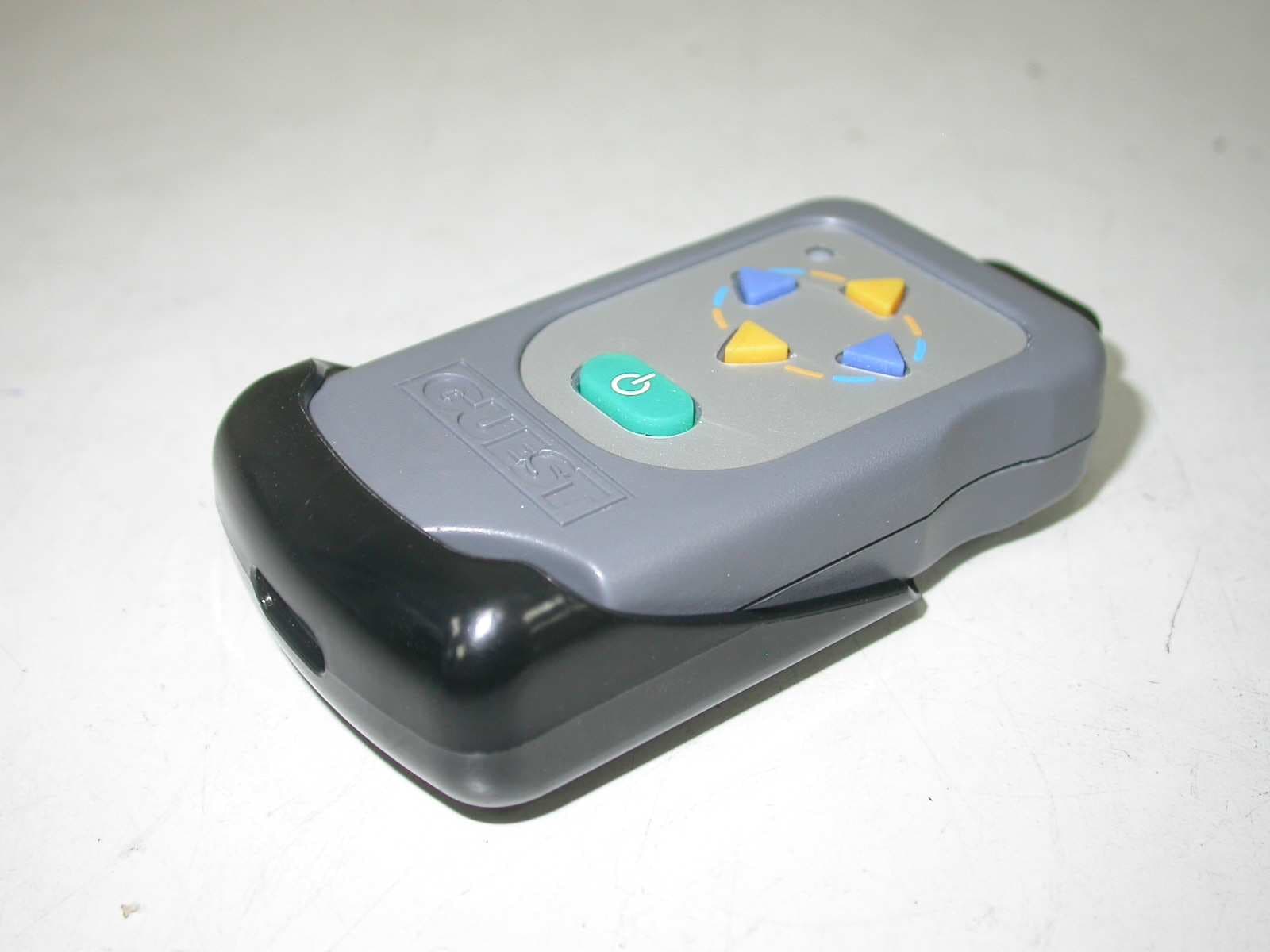
Click to zoom
Application Details
- Equipment Class
- DSC - Part 15 Security/Remote Control Transmitter
- Date of Grant
- Jun 04, 2006
- Application Purpose
- Original Equipment
- Date of Application
- Jun 04, 2006
- Equipment Note
- Wireless Control for 501 Spotlight
- Frequency Range
- 433.92000000 - 433.92000000
- Company
- Atlantic Guest Inc
- Country
- United States
Documents & Files
Document Text
Text extracted from the exhibit documents filed with the FCC. Open a document above to read the original.
Users Manual
MODEL 501 RADIO CONTROLLED REMOTE SPOTLIGHT INSTALLATION AND OPERATION INSTRUCTIONS IMPORTANT ! READ THESE INSTRUCTIONS BEFORE INSTALLING AND USING THIS PRODUCT. KEEP THESE INSTRUCTIONS FOR FUTURE REFERENCE 2 CAUTION! THE MODEL 501 COMPLIES WITH PART 15 OF THE FEDERAL COMMUNICATIONS COMMISSION RULES. CHANGES OR MODIFICATIONS NOT EXPRESSLY APPROVED BY THE GUEST COMPANY MAY VOID YOUR AUTHORITY TO OPERATE THE SPOTLIGHT! The GUEST 501 BEAMER remote control spotlight consists of: (1) The Spotlight / Receiver (2) The hand held wireless remote (R.F. Transmitter). Item 1 is powered by 12 Volts D.C. Item 2 is powered by a 12 Volt Alkaline Battery (provided with unit). See section titled “Installing Transmitter Battery”. Installation Range of operation of the wireless remote (R.F. Transmitter) is approximately 100 feet under ideal conditions. The following will reduce the range: (1) A weak 12 Volt Alkaline Battery in the Transmitter. (2) Local radio interference. (3) Obstacles between the wireless remote (R.F. Transmitter) and Spotlight. To provide control in the event of temporary signal loss or loss of your R.F. Transmitter, we strongly suggest you replace the transmitter battery on a regular basis. This unit is designed for 12 volt DC operation only. CAUTION! TO HELP PREVENT POSSIBLE SIGNAL LOSS , CHANGE BATTERIES YEARLY OR MORE OFTEN WITH EXTENDED USE . Mounting the Spotlight 1. Select a horizontal, smooth surface to mount the spotlight in an upright position (not upside down). Be sure you will have access to the underside of the chosen location, and that you will be able to drill holes there without damaging existing wiring or 3 structures. Avoid locations where lines, anchors, sails or other hazards might damage the light. NOTE: Mounting the light as far forward or as high as possible can help to reduce reflected glare from the deck when the light is in use. 2. Remove the foam gasket from the base of the spotlight and use it as a template. NOTE: Front mounting holes are further apart than rear holes. Mark the location of the four corner holes and the center hole squarely onto the mounting surface with pencil. 3. Drill five 5/16" (7mm) holes through the mounting surface at the marked points. NOTE: Always wear eye protection when using power tools. 4. Return the foam gasket to the base of the spotlight, making sure that the two wires exit through the center hole in the gasket. 5. Feed the two wires coming out of the base of the light through the center hole in the mounting surface. A small amount of a non-silicone sealant, (such as StarBrite Boat Caulk #83801), can be applied to where the bolts and the wires penetrate the mounting surface. CAUTION! SILICONE BASED SEALANTS MAY CAUSE DAMAGE TO THE FOAM GASKET, OR TO THE BASE OF THE SPOTLIGHT. 6. A Marine grade plywood back plate is recommended to strengthen the installation. 7. Place the light on the mounting surface, lens facing forward, and align the 4 holes in the light base and the foam gasket with the 4 corner holes drilled into the mounting surface 8. Fasten the spotlight securely to the mounting surface using four 1/4" (6mm) stainless steel Pan head screws, large flat washers, lock washers and nuts. Do not over tighten. 9. It is recommended that the base of the spotlight be sealed to the mounting surface using non-silicone sealant as in #5 above after installation for complete waterproofing. 4 Installing Transmitter Battery Note: Battery is included, but not installed to help prevent loss of battery strength when new. (1) Remove any static charges from your body by touching a metal grounded object. (2) Remove Transmitter from console mounting bracket, by slightly bending the tab back to release the transmitter from the bracket. (3) Remove the two screws on the back of the transmitter with a Philips screwdriver. With a coin, lightly pry open the transmitter case using the slot in the bottom corner opposite of the key ring hole. (4) Carefully separate the case halves. See illustration for disassembly below. (5) Place the 12 Volt Alkaline A23 battery in location per Figure 1 below paying close attention to the + / - orientation. Slot Tab (2) 5 NOTE: If you wish to change the security code for your light, skip to the section titled: Changing the Security Code – OPTIONAL Then return here for re-assembly instructions. (6) Make sure membrane and top cover is re- assembled correctly with buttons protruding fully. (7) Carefully snap top cover / membrane on to lower assembly. It should only take light pressure to snap in place. (8) Test battery connection by pressing any of the buttons. When doing so, the red LED indicator should turn on in the upper left hand corner. If the LED does not illuminate, separate the covers and check the battery polarity, if correct replace with another battery. SEE FIGURE 1 BELOW. FIGURE 1 (9) Re-install the 2 screws on the back cover and tighten them Changing the Security Code - OPTIONAL There are 64 codes available in the system. They are selected by means of an 8- position code switch. There is a code switch in the wireless remote (RF Transmitter). LED location 6 NOTICE A LL RADIO C ONTROLLED R EMOTE S POTLIGHTS ARE FACTORY SET TO THE SAME SECURITY CODE . I F YOU HAVE A PROBLEM WITH ANOTHER PERSON ’ S SPOTLIGHT INTERACTING WITH YOUR SPOTLIGHT , OR WISH TO CHANGE YOUR SECURITY CODE FOR ANY REASON , FOLLOW THE PROCEDURE OUTLINED BELOW . A. Disconnect Power to the spotlight. B. Adjust Security Code (Perform steps listed below in Code switch Location and Adjustment section). C. Reconnect Power. D. Within 5 seconds of reconnecting power, push transmitter buttons to register security code. Code Switch Location and Adjustment The Code switch is located inside of the transmitter on the backside of the circuit board, above the battery. A. Remove any static charges from your body by touching a grounded metal object. B. Remove transmitter from console mounting bracket by slightly bending the tab back to release transmitter…
Text truncated - open the document above for the full version.
External Photos
ETC Report No.: 06-03-MAS-244-01 Page A1 of A1 FCC ID.: CCW501 ANNEX A: EXTERNAL CONSTRUCTION PHOTOS OF EUT 1. Outside view 1 of EUT 2. Outside view 2 of EUT
ID Label/Location Info
FCC ID:CCW501 MADE IN CHINA This device complies with Part 15 of the FCC Rules. Operation is subject to the following two conditions: (1) this device may not cause harmful interference, and (2) this device must accept any interference received, including interference that may cause undesired operation. THE GUEST CO. Model 501 & 505 #728295 1.04’’ +.00 0.78’’ +. 00
Internal Photos
ETC Report No.: 06-03-MAS-244-01 Page B1 of B3 FCC ID.: CCW501 ANNEX B: INTERNAL CONSTRUCTION PHOTOS OF EUT 1. Inside View 1 of EUT 2. Inside View 2 of EUT ETC Report No.: 06-03-MAS-244-01 Page B2 of B3 FCC ID.: CCW501 3. Inside View 3 of EUT 4. Front view of PCB ETC Report No.: 06-03-MAS-244-01 Page B3 of B3 FCC ID.: CCW501 5. Rear view of PCB
Test Report
ETC Report No. : 06-03-MAS-244-01 Sheet 1 of 23 Sheets FCC ID.: CCW501 Rev. No 1.0 CONFORMANCE TEST REPORT FOR FCC 47 CFR, Part 15 Subpart C Report No.: 06-03-MAS-244-01 Client: Atlantic Guest Inc Product: Wireless Control for 501 spotlight Model: Guest No.728295 FCC ID: CCW501 Manufacturer/supplier: Atlantic Guest Inc Date test item received: 2006/03/24 Date test campaign completed: 2006/04/27 Date of issue: 2006/05/23 The test result only corresponds to the tested sample. It is not permitted to copy this report, in part or in full, without the permission of the test laboratory. Total number of pages of this test report: 23 pages Total number of pages of photos: External photos 1 pages Internal photos 3 pages Setup photos 2 pages Test Engineer Checked By Approved By Jeng De Hsu James Joe Hsieh ELECTRONICS TESTING CENTER, TAIWAN NO.8, LANE 29, WENMING RD., LESHAN TSUEN, GUISHAN SHIANG, TAOYUAN COUNTY, TAIWAN 33383, R.O.C. TEL: (03) 3276170~4 INT: +886-3-3276170~4 FAX: (03) 3276188 INT: +886-3-3276188 ETC Report No. : 06-03-MAS-244-01 Sheet 2 of 23 Sheets FCC ID.: CCW501 Rev. No 1.0 Client : Atlantic Guest Inc Address : 95 research parkway,Meriden 06450,U.S.A. Manufacturer : Atlantic Guest Inc Address : 95 research parkway,Meriden 06450,U.S.A. EUT : Wireless Control for 501 spotlight Trade name : Guest Model No. : Guest No.728295 Power Source : 12V DC Regulations applied : FCC 47 CFR, Part 15 Subpart C (2005) The testing described in this report has been carried out to the best of our knowledge and ability, and our responsibility is limited to the exercise of reasonable care. This certification is not intended to believe the sellers from their legal and/or contractual obligations. The compliance test is only certified for the test equipment and the results of the testing report relate only to the item tested. The compliance test of this report was conducted in accordance with the appropriate standards. It’s not intention to assure the quality and performance of the product. This report shall not be reproduced except in full, without the approval of ETC. This report must not be used by the client to claim product endorsement by NVLAP or any agency of the U.S. Government. Laboratory Introduction: Electronics Testing Center, Taiwan is recognized, filed and mutual recognition arrangement as following: 1 ISO9001: TüV Product Service 2 ISO/IEC 17025: BSMI, CNLA, DGT, NVLAP, CCIBLAC, UL, Compliance 3 Filing: FCC, Industry Canada, VCCI 4 MRA: Australia, Hong Kong, New Zealand, Singapore, USA, Japan, Korea, China, APLAC through CNLA 5 FCC Registration Number: 90588, 91094, 91095 NVLAP Lab Code 200133-0 ETC Report No. : 06-03-MAS-244-01 Sheet 3 of 23 Sheets FCC ID.: CCW501 Rev. No 1.0 Table of Contents Page 1. GENERAL INFORMATION ......................................................................................................................................4 1.1 PRODUCT DESCRIPTION.................................................................................................................................................4 1.2 CHARACTERISTICS OF DEVICE:......................................................................................................................................4 1.3 TEST METHODOLOGY....................................................................................................................................................4 1.4 TEST FACILITY...............................................................................................................................................................4 2. DEFINITION AND LIMITS........................................................................................................................................5 2.1 DEFINITION....................................................................................................................................................................5 2.2 RESTRICTED BANDS OF OPERATION...............................................................................................................................5 2.3 LIMITATION....................................................................................................................................................................6 2.4 LABELING REQUIREMENT..............................................................................................................................................7 2.5 USER INFORMATION.......................................................................................................................................................7 3. RADIATED EMISSION MEASUREMENT..............................................................................................................8 3.1 APPLICABLE STANDARD.................................................................................................................................................8 3.2 MEASUREMENT PROCEDURE.........................................................................................................................................8 3.3 TEST DATA..................................................................................................................................................................10 3.4 FIELD STRENGTH CALCULATION..................................................................................................................................13 3.5 RADIATED TEST EQUIPMENT.......................................................................................................................................13 3.6 MEASURING INSTRUMENT SETUP.................................................................................................................................18 4. BANDWIDTH OF EMISSION..................................................................................................................................19 4.1 APPLICABLE STANDARD PLOT GRAPHIC OF BANDWIDTH..................................…
Text truncated - open the document above for the full version.
Test Setup Photos
ETC Report No.:06-03-MAS-244-01 Sheet 1 of 2 Sheets FCC ID.: CCW501 Radiated Measurement Photos x-axis ETC Report No.:06-03-MAS-244-01 Sheet 2 of 2 Sheets FCC ID.: CCW501 y-axis z-axis
Contact Information
Applicant
Sonya L Cook
Test Firm
Electronics Testing Center, TaiwanWin-Po Tsai
Technical Specifications
| # | Rule Parts | Frequency Range | Power Output |
|---|---|---|---|
| 1 | 15.231 | 433.92 MHz - 433.92 MHz | - |
Other Applications from Atlantic Guest Inc
CCW95300000
Apr 03, 1996TNB - Licensed Non-Broadcast Station Transmitter
Equipment Class
TNB - Licensed Non-Broadcast Station TransmitterCCW95200000-02
Apr 02, 1996GEP - 406 MHz EPIRB
Equipment Class
GEP - 406 MHz EPIRBCCW292T
Jun 11, 1991Radio Controlled Spotlight Transmitter
Equipment Class
DXX - Part 15 Low Power Communication Device TransmitterCCW292R
May 07, 1991Spotlight Receiver
Equipment Class
CYY - Communications Receiver used w/Pt 15 TransmitterCCW8GJ-630A
Sep 05, 1990TNB - Licensed Non-Broadcast Station Transmitter
Equipment Class
TNB - Licensed Non-Broadcast Station Transmitter