CEKDVM-9601FFeeder radio vehicle communication system
Daifuku Co Ltd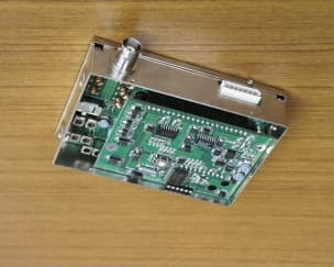
Click to zoom
Application Details
- Equipment Class
- DSC - Part 15 Security/Remote Control Transmitter
- Date of Grant
- Sep 24, 2000
- Application Purpose
- Original Equipment
- Date of Application
- Jun 29, 1999
- Equipment Note
- Feeder radio vehicle communication system
- Frequency Range
- 221.90000000 - 221.90000000
- Company
- Daifuku Co Ltd
- Country
- Japan
Documents & Files
Document Text
Text extracted from the exhibit documents filed with the FCC. Open a document above to read the original.
Attestation Statements
June 30, 1999 Confidentiality Statement to Accompany FCC Form 731 Form 731 Confirmation Number: EA94701 FCC ID: CEKDVM-9601F To Whom It May Concern: Daifuku wishes the frequency bands and output power reported in Form 731 and in the accompanying test report to remain confidential. The system in question is used as a communication device in an automatic material handling system. Daifuku wants this information to remain confidential from its competitors who supply similar material handling systems. Regards, Mark Magleby Assistant Manager, Engineering DAIFUKU AMERICA CORPORATION Clean FA Division Utah Office 5225 W. Wiley Post Way, Suite 125 Salt Lake City, Utah 84116 Phone: (801) 595-6500 Fax: (801) 595-0123
Attestation Statements
September 21, 2000 Confidentiality Statement to Accompany FCC Form 731 Form 731 Confirmation Number: EA94701 FCC ID: CEKDVM-9601F To Whom It May Concern: This document supercedes the document submitted to the FCC on June 30, 1999 (filename: 990630A FCC confidentiality statement.doc). The applicant (Daifuku Co., Ltd., Japan) requests that the exhibit submitted to the FCC as filename “000921 FCC Schematics.doc” on September 21, 2000 remain confidential. The schematic diagrams are the property of Sankyo Tokushu Musen Co., Ltd., a supplier to Daifuku Co., Ltd. Daifuku and Sankyo Tokushu Musen have a non-disclosure agreement in force that prohibits Daifuku from disclosing the schematic diagrams to a third party without the permission of Sankyo Tokushu Musen. Sankyo Tokushu Musen has granted Daifuku permission to disclose the schematics to the FCC for the purposes of this application. A copy of this statement is attached to the exhibit in accordance with FCC rules section 0.459 (a). Regards, Mark Magleby Assistant Manager, Engineering Daifuku America Corporation DAI FUKU AM ERI CA CORP ORAT IO N Clean FA Division Utah Office 5225 W. Wiley Post Way, Suite 125 Salt Lake City, Utah 84116 Phone: (801) 595-6500 Fax: (801) 595-0123
External Photos
FCC ID: CEKDVM-9601F Form 731 Confirmation Number: EA94701 External photo of vehicle modem (part number DVM-19201) External photo of controller modem (part number DVM-19202) Internal photo of vehicle modem (part number DVM-19201) Internal photo of controller modem (part number DVM-19202) Note: this copy of this exhibit supercedes the exhibit submitted previously to the FCC on August 14, 2000 (filename “000814 FCC photos and schematics.doc”).
ID Label/Location Info
FCC ID: CEKDVM-9601F This device complies with part 15 of the FCC Rules. Operation is subject to the following two conditions: (1) This device may not cause harmful interference, and (2) this device must accept any interference received, including interference that may cause undesired operation.
Schematics
FCC ID: CEKDVM-9601F 731 Confirmation Number: 13668 External photo of vehicle modem (part number DVM-19201) External photo of controller modem (part number DVM-19202) Internal photo of vehicle modem (part number DVM-19201) Internal photo of controller modem (part number DVM-19202) FCC ID: CEKDVM-9601F 731 Confirmation Number: 13668 Schematic of vehicle modem (part number DVM-19201)—CONFIDENTIAL FCC ID: CEKDVM-9601F 731 Confirmation Number: 13668 Schematic of controller modem (part number DVM-19202)—CONDFIDENTIAL FCC ID: CEKDVM-9601F 731 Confirmation Number: 13668 Schematic of transceiver logic (used in both part number DVM-19201 and DVM-19202)— CONFIDENTIAL
Test Report
DAIFUKU AMERICA CORP. DAIFUKU CFA—K. Ueda/M. Magleby—11/23/1999 Page 1 of 6 FCC-compliant Feeder Radio Test Results Daifuku has tested the CSC-500 OHT to ensure that modifications made to the feeder radio system did not cause communication errors. The results of the test are given below. 1. Test date/time:May 8, 1999/1:00 p.m. 2. Test location:Daifuku Shiga Factory, I Building, 300mm test line 3. Test engineers:Daifuku: Ito, Ueda Sankyo Tokushu Musen: 4 engineers 4. Modem frequencies during test: Original vehicleFCC-compliant vehicle Vehicle sideController sideVehicle sideController side Model DVM-9601G12 Ch. ADVM-9602D Ch. A TBDTBD Frequency138.15 MHz170.15 MHz151.9 MHz221.9 MHz Field Strength 500 μV/m500 μV/m150 μV/m200 μV/m 5. Test locations along the track and distances between feeder line and vehicle modem: Distance between feeder line and track surface Distance between feeder line and vehicle modem Point A (straight)23 mm26 mm Point B (curve)23 mm55 mm 6. Test method: 1) Original modem • Stopped the vehicle at points A and B and measured the field strength generated • Stopped the vehicle at points A and B, transmitted a radio message 1,000 times and counted the number of communication errors Maintenance shifter CMS-1 A B DAIFUKU AMERICA CORP. DAIFUKU CFA—K. Ueda/M. Magleby—11/23/1999 Page 2 of 6 2) FCC-compliant modem • Set the field strength to each of the values in the following table, stopped the vehicle at point A and measured the field strength generated • For each field strength, stopped the vehicle at points A and B, transmitted a radio message 1,000 times and counted the number of communication errors Field strength settings: Vehicle sideController side Test 1 150 μV/m200 μV/m Test 2 112 μV/m158 μV/m Test 3 100 μV/m126 μV/m Field strength measurements were taken with the antenna positioned exactly 3 m from the feeder line as shown in the photograph at the right. 7. Field strength meter and measurement conditions 1) AntennaName: tablet in-air line (antenna) Model: MZ18A Manufacturer: Anritsu MeterName: Interference/Field Strength Meter Model: ML518A Manufacturer: Anritsu 2) Measurement conditions All measurements were made with the target vehicle operating and the other vehicle powered OFF 8. FCC requirements summary (taken from pages 16-17 of OET BULLETIN NO. 63 published by the FCC): Frequency BandBand UsageField Strength @ 3 m 138-149.9 MHz (original modem)Approved ≤ 150 μV/m 167.72-173.2 MHz (original modem)Prohibited 150.05-156.52 MHz (FCC-compliant modem)Approved ≤ 150 μV/m 216-240 MHz (FCC-compliant modem)Approved ≤ 200 μV/m 9. Test results: The field strength meter displays measurements in decibels. The following equation was used to convert decibels to microvolts per meter: log 10 (μV/m) = (dB/20). Antenna 3 m Meter Feeder line DAIFUKU AMERICA CORP. DAIFUKU CFA—K. Ueda/M. Magleby—11/23/1999 Page 3 of 6 1) Original modem Measurement locationPoint A (straight)Point B (curve) Vehicle side (138.15 MHz) 398.1 μV/m (52 dB)501.2 μV/m (54 dB) Field Strength Controller side (170.15 MHz) 631.0 μV/m (56 dB)251.2 μV/m (48 dB) No. of communication errors (out of 1,000 repetitions)1No errors 2) FCC-compliant modem Measurement locationPoint A (straight)Point B (curve) TEST 1 Vehicle side (151.9 MHz) 141.3 μV/m (43 dB) Field Strength Controller side (221.9 MHz) 199.5 μV/m (46 dB) No. of communication errors (out of 1,000 repetitions)No errorsNo errors TEST 2 (field strength reduced 2 dB from test 1) Vehicle side (151.9 MHz) 112.2 μV/m (41 dB) Field Strength Controller side (221.9 MHz) 158.5 μV/m (44 dB) No. of communication errors (out of 1,000 repetitions)No errorsNo errors TEST 3 (field strength reduced 2 dB from test 2) Vehicle side (151.9 MHz) 100 μV/m (40 dB) Field Strength Controller side (221.9 MHz) 125.9 μV/m (42 dB) No. of communication errors (out of 1,000 repetitions)No errorsNo errors 10. Conclusions: Daifuku concludes that with the following measures implemented, it is possible to operate the CSC-500 with an FCC-compliant feeder radio system: • Separate the feeder line from the metal track • Minimize the distance between the feeder line and the vehicle modem The transmission field strength was observed to fluctuate depending on the surrounding environment and measurement position (inside the track vs. outside the track for example). For this reason, field strength settings were adjusted at the optimum (field strength most stable) location on the test line, which was point A. DAIFUKU AMERICA CORP. DAIFUKU CFA—K. Ueda/M. Magleby—11/23/1999 Page 4 of 6 FCC Appendix The following appendix is provided to ensure that all information requested in section 2.1033 of the FCC Rules is included in this report. The content of the report preceding this appendix is unchanged from the original document submitted earlier to the FCC along with Form 731. The only change to the preceding pages is the replacement of the words “DAIFUKU CONFIDENTIAL” with “DAIFUKU AMERICA CORP.” in the page footer. 2.1033 (b) (1) Manufacturer name and mailing address Manufacturer: Daifuku Co., Ltd. 1500, Komakihara-shinden Komaki City, Aichi 485-8653 JAPAN OR Daifuku Co., Ltd. 2-14-5 Shiba, Minato-ku Tokyo 105 JAPAN (this is the address given on form 731) Applicant: Mark Magleby Daifuku America Corporation 5225 W. Wiley Post Way, Ste. 125 Salt Lake City, UT 84116 2.1033 (b) (2) FCC Identifier The FCC identifier of the device is CEKDVM-9601F. 2.1033 (b) (3) Installation and operating instructions The device in question is a low-level communications device used in an automatic vehicle transportation system. The manufacturer performs all installation, and operation of the device is completely transparent to the user. There are no installation or operation instructions furnished to the user. 2.1033 (b) (4) Brief description of the circuit functions of the device and device operation The overall system where the radio device is used is an automated material handling system used in semiconductor cleanrooms. The sy…
Text truncated - open the document above for the full version.
Test Report
DAIFUKU AMERICA CORP. DAIFUKU CFA—K. Ueda/M. Magleby—11/23/1999 Page 1 of 6 FCC-compliant Feeder Radio Test Results Daifuku has tested the CSC-500 OHT to ensure that modifications made to the feeder radio system did not cause communication errors. The results of the test are given below. 1. Test date/time:May 8, 1999/1:00 p.m. 2. Test location:Daifuku Shiga Factory, I Building, 300mm test line 3. Test engineers:Daifuku: Ito, Ueda Sankyo Tokushu Musen: 4 engineers 4. Modem frequencies during test: Original vehicleFCC-compliant vehicle Vehicle sideController sideVehicle sideController side Model DVM-9601G12 Ch. ADVM-9602D Ch. A TBDTBD Frequency138.15 MHz170.15 MHz151.9 MHz221.9 MHz Field Strength 500 μV/m500 μV/m150 μV/m200 μV/m 5. Test locations along the track and distances between feeder line and vehicle modem: Distance between feeder line and track surface Distance between feeder line and vehicle modem Point A (straight)23 mm26 mm Point B (curve)23 mm55 mm 6. Test method: 1) Original modem • Stopped the vehicle at points A and B and measured the field strength generated • Stopped the vehicle at points A and B, transmitted a radio message 1,000 times and counted the number of communication errors Maintenance shifter CMS-1 A B DAIFUKU AMERICA CORP. DAIFUKU CFA—K. Ueda/M. Magleby—11/23/1999 Page 2 of 6 2) FCC-compliant modem • Set the field strength to each of the values in the following table, stopped the vehicle at point A and measured the field strength generated • For each field strength, stopped the vehicle at points A and B, transmitted a radio message 1,000 times and counted the number of communication errors Field strength settings: Vehicle sideController side Test 1 150 μV/m200 μV/m Test 2 112 μV/m158 μV/m Test 3 100 μV/m126 μV/m Field strength measurements were taken with the antenna positioned exactly 3 m from the feeder line as shown in the photograph at the right. 7. Field strength meter and measurement conditions 1) AntennaName: tablet in-air line (antenna) Model: MZ18A Manufacturer: Anritsu MeterName: Interference/Field Strength Meter Model: ML518A Manufacturer: Anritsu 2) Measurement conditions All measurements were made with the target vehicle operating and the other vehicle powered OFF 8. FCC requirements summary (taken from pages 16-17 of OET BULLETIN NO. 63 published by the FCC): Frequency BandBand UsageField Strength @ 3 m 138-149.9 MHz (original modem)Approved ≤ 150 μV/m 167.72-173.2 MHz (original modem)Prohibited 150.05-156.52 MHz (FCC-compliant modem)Approved ≤ 150 μV/m 216-240 MHz (FCC-compliant modem)Approved ≤ 200 μV/m 9. Test results: The field strength meter displays measurements in decibels. The following equation was used to convert decibels to microvolts per meter: log 10 (μV/m) = (dB/20). Antenna 3 m Meter Feeder line DAIFUKU AMERICA CORP. DAIFUKU CFA—K. Ueda/M. Magleby—11/23/1999 Page 3 of 6 1) Original modem Measurement locationPoint A (straight)Point B (curve) Vehicle side (138.15 MHz) 398.1 μV/m (52 dB)501.2 μV/m (54 dB) Field Strength Controller side (170.15 MHz) 631.0 μV/m (56 dB)251.2 μV/m (48 dB) No. of communication errors (out of 1,000 repetitions)1No errors 2) FCC-compliant modem Measurement locationPoint A (straight)Point B (curve) TEST 1 Vehicle side (151.9 MHz) 141.3 μV/m (43 dB) Field Strength Controller side (221.9 MHz) 199.5 μV/m (46 dB) No. of communication errors (out of 1,000 repetitions)No errorsNo errors TEST 2 (field strength reduced 2 dB from test 1) Vehicle side (151.9 MHz) 112.2 μV/m (41 dB) Field Strength Controller side (221.9 MHz) 158.5 μV/m (44 dB) No. of communication errors (out of 1,000 repetitions)No errorsNo errors TEST 3 (field strength reduced 2 dB from test 2) Vehicle side (151.9 MHz) 100 μV/m (40 dB) Field Strength Controller side (221.9 MHz) 125.9 μV/m (42 dB) No. of communication errors (out of 1,000 repetitions)No errorsNo errors 10. Conclusions: Daifuku concludes that with the following measures implemented, it is possible to operate the CSC-500 with an FCC-compliant feeder radio system: • Separate the feeder line from the metal track • Minimize the distance between the feeder line and the vehicle modem The transmission field strength was observed to fluctuate depending on the surrounding environment and measurement position (inside the track vs. outside the track for example). For this reason, field strength settings were adjusted at the optimum (field strength most stable) location on the test line, which was point A. DAIFUKU AMERICA CORP. DAIFUKU CFA—K. Ueda/M. Magleby—11/23/1999 Page 4 of 6 FCC Appendix The following appendix is provided to ensure that all information requested in section 2.1033 of the FCC Rules is included in this report. The content of the report preceding this appendix is unchanged from the original document submitted earlier to the FCC along with Form 731. The only change to the preceding pages is the replacement of the words “DAIFUKU CONFIDENTIAL” with “DAIFUKU AMERICA CORP.” in the page footer. 2.1033 (b) (1) Manufacturer name and mailing address Manufacturer: Daifuku Co., Ltd. 1500, Komakihara-shinden Komaki City, Aichi 485-8653 JAPAN OR Daifuku Co., Ltd. 2-14-5 Shiba, Minato-ku Tokyo 105 JAPAN (this is the address given on form 731) Applicant: Mark Magleby Daifuku America Corporation 5225 W. Wiley Post Way, Ste. 125 Salt Lake City, UT 84116 2.1033 (b) (2) FCC Identifier The FCC identifier of the device is CEKDVM-9601F. 2.1033 (b) (3) Installation and operating instructions The device in question is a low-level communications device used in an automatic vehicle transportation system. The manufacturer performs all installation, and operation of the device is completely transparent to the user. There are no installation or operation instructions furnished to the user. 2.1033 (b) (4) Brief description of the circuit functions of the device and device operation The overall system where the radio device is used is an automated material handling system used in semiconductor cleanrooms. The sy…
Text truncated - open the document above for the full version.
Contact Information
Applicant
Isamu Mabuchi
Technical Contact
Daifuku America CorporationMark V Magleby
[email protected]801-595-6500
5225 West Wiley Post Way · Salt Lake City, Utah · United States
Non-Technical Contact
Daifuku America CorporationMark V Magleby
[email protected]801-595-6500
Test Firm
CONTEC EMS Co., LTDYoshinori Osakabe
Technical Specifications
| # | Rule Parts | Frequency Range | Power Output |
|---|---|---|---|
| 2 | - | 221.9 MHz - 221.9 MHz | - |
Other Applications from Daifuku Co Ltd
CEK8ETDVM01
Oct 01, 1989Radio Control Transmitter
Equipment Class
DSC - Part 15 Security/Remote Control TransmitterCEK8ETDVM02
Oct 01, 1989Radio Control Transmitter
Equipment Class
DSC - Part 15 Security/Remote Control TransmitterCEK8ETRF001
May 17, 1989DCD - Part 15 Low Power Transmitter Below 1705 kHz
Equipment Class
DCD - Part 15 Low Power Transmitter Below 1705 kHzCEK8ETCE003
Nov 20, 1986DCD - Part 15 Low Power Transmitter Below 1705 kHz
Equipment Class
DCD - Part 15 Low Power Transmitter Below 1705 kHzCEK8ETCE004
Nov 20, 1986DCD - Part 15 Low Power Transmitter Below 1705 kHz
Equipment Class
DCD - Part 15 Low Power Transmitter Below 1705 kHz