CGK8001001Spread Spectrum Transmitter Module
Ericsson Radio Systems BV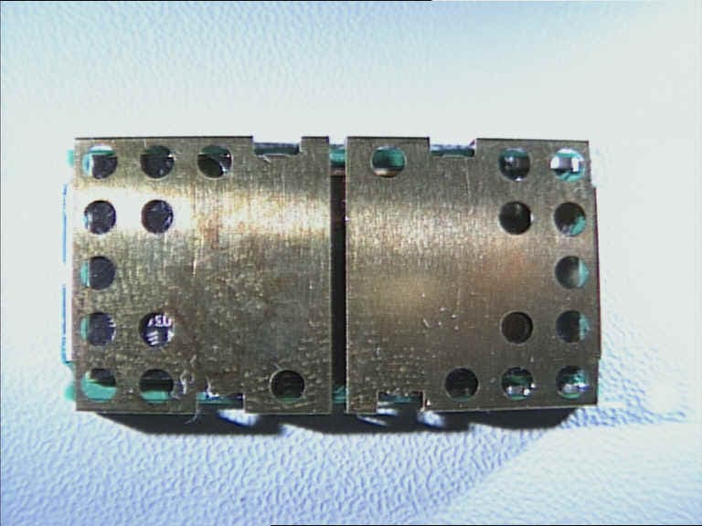
Click to zoom
Application Details
- Equipment Class
- DSS - Part 15 Spread Spectrum Transmitter
- Date of Grant
- Jul 05, 2000
- Application Purpose
- Original Equipment
- Date of Application
- Apr 03, 2000
- Equipment Note
- Spread Spectrum Transmitter Module
- Frequency Range
- 2402.00000000 - 2480.00000000
- Company
- Ericsson Radio Systems BV
- Country
- Netherlands
Documents & Files

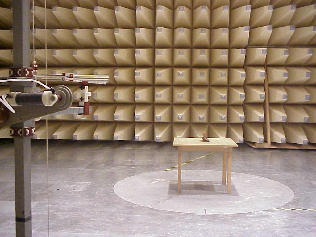
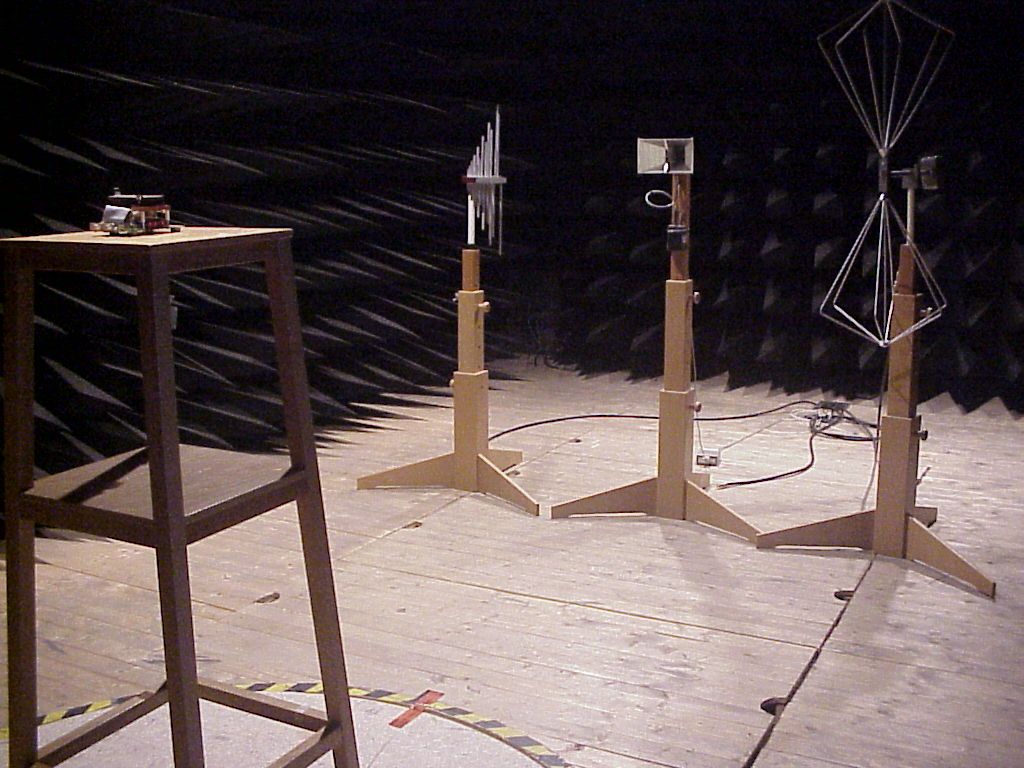
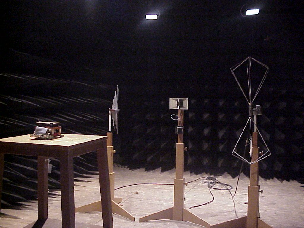
Document Text
Text extracted from the exhibit documents filed with the FCC. Open a document above to read the original.
Cover Letter(s)
Certification Of Agency Agreement I appoint Phillip Inglis, to act as agent for our organization in the preparation of applications, including the signing there of, to make representations to the Federal Communications Commission on our behalf and to receive and exchange data between the two parties: Federal Communications Commission And Cetecom Contact information for Mr. Inglis: Phillip Inglis, Cetecom b.v.b.a., MDPhone: 410-531-3439 14085 Howard Rd.Fax: 410-531-0807 Dayton, MD 21036Email: [email protected] It is further understood that all information supplied to Mr. Inglis as representations of Cetecom, i.e., FCC ID labels, schematics, instruction manuals, etc., will continue to comply in production; that each unit manufactured, imported or marketed, as defined in the Commissions Regulations, will conform to the sample tested within the variations that can be expected due to quantity production and testing on a statistical basis; will comply with the FCC requirements. Dated this ________ day of ____________. Agency expiration date: __________________________. By: __________________ ___________________. Signature Printed Title:_________Telephone 011-322-751-8236 Applicants agent:Cetecom b.v.b.a., Belgium Phillip Inglis, Cetecom b.v.b.a., Maryland
Cover Letter(s)
Response to email dated May 11, 2000 regarding additional information to be filed regarding Ericsson’s Bluetooth module. EA Number EA97254 Question 1. Depending on the product that the module is used with, the final device could be subject to routine evaluation for rf exposure, either SAR limits or MPE limits. However, the maximum rf power output from the module is 0 dBm or 1 milliwatt. The device is also designed to use a quarter wave monopole antenna with a nominal gain of 0dBi as the radiating element. If the entire rf power output were absorbed by 1 gram of tissue (not possible considering typical rf circuits), the SAR limit would still not be exceeded. Further, with a separation distance of 20 cm or greater, the MPE limits are well above the potential this device is capable of producing. There has been some discussion regarding the potential the module could exhibit for altering the ground currents in devices such as cell phones and pcs phones. However, these devices could not be retrofitted with a module the size of the Ericsson module without a redesign of phone to accommodate the additional space and the requirement for connecting data interfaces between the module and the phone. This redesign would require submission of the modified phone to the FCC for certification as a new phone. Thus, rf exposure issues related to a device such as a pcs or cell phone would be addressed at that time. Question 2. I am preparing a letter accepting your position that the internal photos and manual cannot be held as confidential. Question 3. The Bluetooth module has three modes of operation with two modes operating under the hybrid provisions of 15.247 and the third operating under the frequency hopping provisions of 15.247. In page mode and inquiry (acquisition) mode, the module uses a hopping sequence consisting of 32 frequencies. In these modes the combined processing gain from direct sequence and hopping operations is greater than 17 dB. In the connection (link) mode the module uses a pseudorandom hopping sequence of 79 channels. Each unit operating as a system member of a piconet will synchronize to the hopping sequence randomly selected by the master unit. Theoretical process gain calculations in the conventional sense do not apply to the direct sequence operation of this equipment. A 68 bit or 72 bit sequence code is correlated to a true or false flag. In an effort to put this in context with typical direct sequence systems this would approximate to a spread/date rate of 18 dB although it is not recommended that this approach be used. Please refer to the measured processing gain report that has been accepted by the FCC (see letter filed with the application) for additional information. Question 4. Please review the following discussion and provide me with your comments. Modular approvals are not specifically addressed in the FCC Rules. Authorization of modules was permitted because the Commission determined that it was in the interest of the public to permit modules to be authorized and that under certain conditions there was little if potential for causing harmful interference. The Commissions policy was written around relatively high power modules that could potentially exceed the EIRP limits specified in the applicable rules if connected to a high gain antenna. This is not the case with the Ericsson module which is designed to be marketed for installation in a multitude of products. To impose a requirement for a permanently attached antenna on a module like the Ericsson module, with a 1 milliwatt output power, would not benefit the public because of the increased cost to the public for the finished product, would not benefit the FCC because of the resultant increase in the number of applications that would be required and would not reduce the potential for causing interference due to levels exceeding the levels permitted by the rules. Ericsson intends to maintain the compliance of their product as follows. The Ericsson specification for the antenna will always be a short monopole configuration with a gain of 0dBi or as close as possible to this figure. Ericsson can provide an antenna if the customer wishes or the customer with sufficient expertise can design their own antenna for use with their product. In order to maintain the esthetic appearance of products, customers need the flexibility to incorporate their own antenna designs. Depending on module location and the overall product design, the antenna may be designed as a trace on a printed circuit board or as an antenna to be mounted external to the unit. For external configurations, the antenna will be connected via a shielded coax cable in accordance with Ericsson’s specifications. Specific instructions will be given to the purchaser of these modules regarding the antenna gain and interconnecting cable requirements to maintain compliance with the FCC Rules and Ericsson will inform purchasers of the need for conducting measurements to insure the finished product meets all applicable FCC requirements.
Cover Letter(s)
Response to email dated May 22, 2000. Question 1) Verify that the frequency range from the center frequency of the lowest channel to the center frequency of the highest channel is 2402-2480 MHz. Response: Please refer to Figure 3 of test report filed May 15. Figure 3 shows the 79 hopping channels with the spectrum plot centered on 2.442 GHz. Using the spectrum analyzer settings as shown, the lowest frequency accessed over a 200 sec period was 2402 MHz. The highest frequency accessed during this same period was 2480 MHz. The center frequency of lowest channel is 2402 MHz and the center frequency of the highest channel is 2480 MHz. Question 2) Verify that the schematic is the only item to be held confidential. Provide a corrected confidential letter. Response: A modified confidentiality request letter can be submitted as part of the application file. This letter request confidentiality for only the schematic. This confirms the earlier email request submitted May 15 to modify the confidentiality request letter to specify that only the schematic should be held confidential. Question 3) Indicate compliance with Section 15.207. Provide test data. Response See the file described as “Line Conducted Data” that has been submitted as part of the application package. The 450 kHz to 30 MHz plot provided was obtained using the Bluetooth test fixture powered from 115 VAC power using the spectrum analyzer settings below. In previous discussion with the FCC, this was considered acceptable. Only one plot is provided since the plots for both AC lines were identical. Span 450 kHz to 30 MHz RBW 10 kHz VBW 10 kHz Sweep - auto Detector - peak Trace - max hold Question 4) Please verify the antenna used for testing. Provide an antenna list indicating the antenna specification(size, type, gain). Additional testing may be required for types of antennas not tested. Response: This module is only used with an omni-directional monopole antenna designed for 0dBi gain. The module was tested with an external antenna that was approximately 3 cm in length, monopole type, with a design gain of 0 dBi. The antenna was directly attached to the RF output port of the module during testing. If the product in which the module is installed requires the antenna to be mounted in a position that direct connection to the module is not possible, a shielded coax cable will be used to connect the module to the antenna. A design where the antenna will be a trace on a printed circuit board is not part of this filing. Question 5) Please provide a few samples of a pseudorandom sequence in the data mode. Response: The following are two examples of possible 79 channel hopping sequences with channels identified as 1 through 79. The channel numbering scheme starts with channel 2 at 2402 MHz with the 79 th channel then appearing at 2480 MHz as channel 80. Sequence a: 2,17,68,55,4,77,56,27,70,80,22,33,57,34,29,79,44,50,3,71,66,36,78,20,67,30,24,11,37,69, 23,7,41,38,63,14,31,59,40,13,6,25,65,15,61,73,58,47,19,28,54,76,74,48,52,75,5,42,64,72, 62,51,60,18,45,53,16,39,46,32,49,43,8,21,9,12,10,26,35 Sequence b: 50,6,41,57,64,14,42,33,79,3,20,38,56,69,75,21,80,23,31,40,45,68,32,28,4,15,34,59,71,61, 70,5,72,13,48,70,39,54,78,7,77,62,30,2,8,55,10,63,12,16,37,11,43,66,25,51,58,74,17,47, 9,29,65,19,53,18,52,36,27,26,44,22,49,24,35,60,73,76,67 Question 6) Please state the receiver input bandwidth in the data mode. Response: The receiver bandwidth is 1 MHz in the data mode. Question 7) Provide a plot showing the 20 dB bandwidth of the data signal at the maximum 1 Mbps rate. Response: Please refer to Figures 1, 2, and 3 of the file described as “Supplemental Test Report” which has been submitted as part of the application package. The channel numbering scheme starts at 2401 designated as channel number 1, 2402 as channel number 2, and so with the 79 th channel occurring at 2480 MHz which is channel number 80. These plots were taken with the following analyzer settings at the maximum data rate. On channel 2 at 2402 MHz the 20 dB bandwidth is 782 kHz. On channel 40 at 2440 MHz the 20 dB bandwidth is 835 kHz. On channel 80 at 2480 MHz the 20 dB bandwidth is 807 kHz. The following spectrum analyzer settings were used. Span = 3 MHz Resolution Bandwidth = approximately 1% of the 20 dB bandwidth Video bandwidth equal to or greater than the resolution bandwidth Detector = peak Trace = max hold Data rate at maximum Sweep = auto Question 8) Provide the following information with regard to the device operating in the page/inquiry mode under the Spread spectrum Hybrid requirements in Section 15.247(f) and Section 15.247(a)1. a) Average time of occupancy plot. Response: Please refer to Figures 4, 5, and 6 for Page Mode operation and Figures 7, 8, and 9 for Inquiry mode operation. These figures are part of the file described as “Supplemental Test Report” which has been forwarded and attached to the application filing for this equipment. An individual transmission on a channel in page mode is 182 microseconds long. During a 12.8 sec time period, the total dwell time on a given channel is 116.5 milliseconds in page mode. In inquiry mode, an individual transmission on a channel is 182 microseconds long. During a 12.8 second time period, the total dwell time on a given channel is 98.5 milliseconds in inquiry mode. The following analyzer settings were used. Span = 0 centered on hopping channel Resolution Bandwidth = 1 MHz Video Bandwidth ≥ Resolution Bandwidth Sweep = as necessary to capture the entire dwell time per hopping channel Detector = peak Trace = max hold b) Power density plot. Response: Please refer to Figures 10 and 11 that are contained in the attachment described as “Supplemental Test Report” which has been submitted as part of the application package. The following analyzer settings were used. There is only one type of data packet in both the inquiry and page modes. The data packet consist of a 68 bit address code. These plots show a power spectral density level of…
Text truncated - open the document above for the full version.
Cover Letter(s)
May 22, 2000 CONFIDENTIALITY REQUEST Federal Communications Commission Authorization and Evaluation Division 7435 Oakland Mills Road Columbia, MD 21046 Re:Ericsson Business Mobile Networks, BV, application for Hybrid Spread Spectrum System, FCC ID CGK8001001 Gentlemen: Ericsson Business Mobile Networks BV, Nieuw Amsterdamsestraat 40, PO Box 20 15, NL-7801 CA Emmen, The Netherlands, herein submits an Application for Equipment Authorization to be followed by submission of a fee for $1075.00 along with Form 159 for certification of a hybrid spread spectrum transmitter under FCC Rules Part 15 as required by the FCC Rules. The original request for confidentiality should be replaced with this request. Ericsson requests, pursuant to 47CFR 0.459, post grant confidentiality for portions of the material contained in this application such that the identified material will be withheld from public inspection following the grant of this authorization. This material, as indicated by request for confidentiality of the item during the electronic submission process and further identified below, includes: 1. Circuit diagrams submitted as Equipment Authorization Electronic Filing attachment: "schematics" Exhibit #5 Specifically, this exhibit contains information relating to circuit function and complexity that could be of benefit to competitors. The material contains trade secrets and confidential information that Ericsson does not customarily release to the public and which is otherwise not generally available to the public. Please contact the undersigned by phone at 410-531-3439, by fax at 410-531-0807, by email at [email protected], or by correspondence at the address below if there are any further questions or additional information needed concerning this filing. Rega rds, (signed) Phillip Inglis, Cetecom b.v.b.a., Maryland 14085 Howard Rd. Dayton, MD. 21036
Cover Letter(s)
June 27, 2000 CONFIDENTIALITY REQUEST Federal Communications Commission Authorization and Evaluation Division 7435 Oakland Mills Road Columbia, MD 21046 Re:Ericsson Business Mobile Networks, BV, application for Hybrid Spread Spectrum System, FCC ID CGK8001001 Gentlemen: This request is to amend the confidentiality request submitted on May 22, 2000 for the referenced equipment. Ericsson Business Mobile Networks BV, Nieuw Amsterdamsestraat 40, PO Box 20 15, NL-7801 CA Emmen, The Netherlands, previously submitted an Application for Equipment Authorization requesting confidentiality of a portion of that application. This action was followed by submission of a fee for $1075.00 along with Form 159 for certification of a hybrid spread spectrum transmitter under FCC Rules Part 15 as required by the FCC Rules. Ericsson requests, pursuant to 47CFR 0.459, post grant confidentiality for portions of the material contained in this application such that the identified material will be withheld from public inspection following the grant of this authorization. This material, as indicated by request for confidentiality of the items during the electronic submission process and further identified below, includes: 1. Circuit diagrams submitted as Equipment Authorization Electronic Filing attachment: "schematics" Exhibit #5 2. The original PROCESSING GAIN report for direct sequence operation as a hybrid spread spectrum transmitter must be kept confidential. The original processing gain report contained confidential proprietary material that would cause harm to Ericsson if released to the public. An amended processing gain report, with the confidential material removed has been forwarded to the file for this equipment. Specifically, the above exhibits contain information relating to circuit function and complexity that could be of benefit to competitors. The material contains trade secrets and confidential information that Ericsson does not customarily release to the public and which is otherwise not generally available to the public. Please contact the undersigned by phone at 410-531-3439, by fax at 410-531-0807, by email at [email protected], or by correspondence at the address below if there are any further questions or additional information needed concerning this filing. Rega rds, (signed) Phillip Inglis, Cetecom b.v.b.a., Maryland 14085 Howard Rd. Dayton, MD. 21036
ID Label/Location Info
FCC ID Label The above label will be affixed to the module, located as specified in the adjacent drawing. For systems using the module where the label will not be visible when the module is installed, an auxiliary label will be provided with instructions to place the label on an exterior surface of the device such that it will be visible upon inspection in compliance with the modular approval guidelines developed by the FCC. This auxiliary label will be identical to the above label. Additionally, in compliance with the requirements of Section 15.19(a)(3) and as permitted by Section 15.19(a)(5)of the Rules, the following statement will be included in the instruction manual provided with the module: This device complies with Part 15 of the FCC Rules. Operation is subject to the following two conditions: (1) this device may not cause harmful interference, and (2) this device must accept any interference received, including interference that may cause undesired operation. FCC ID:CGK8001001 FCC ID: CGK8001001 Top surface of the module
RF Exposure Info
RF exposure compliance issues: Depending on the product that the module is used with, the final device could be subject to routine evaluation for rf exposure, either SAR limits or MPE limits. However, the maximum rf power output from the module is 0 dBm or 1 milliwatt. The device is also designed to use a quarter wave monopole antenna with a nominal gain of 0dBi as the radiating element. If the entire rf power output were absorbed by 1 gram of tissue (not possible considering typical rf circuits), the SAR limit would still not be exceeded. Further, with a separation distance of 20 cm or greater, the MPE limits are well above the potential a 1 milliwatt device is capable of producing. There has been some discussion regarding the potential the module could exhibit for altering the ground currents in devices such as cell phones and pcs phones. However, these devices could not be retrofitted with a module the size of the Ericsson module without a redesign of the phone to accommodate the additional space and the requirement for connecting data interfaces between the module and the phone. This redesign would require submission of the modified phone to the FCC for certification as a new phone. Thus, rf exposure issues related installation of this module in a device such as a pcs or cell phone would be addressed by the certification requirement.
Test Report
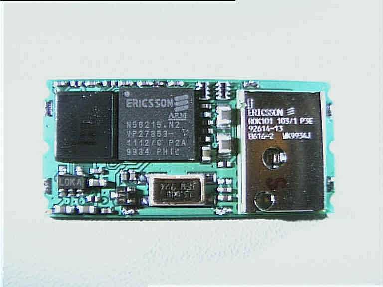
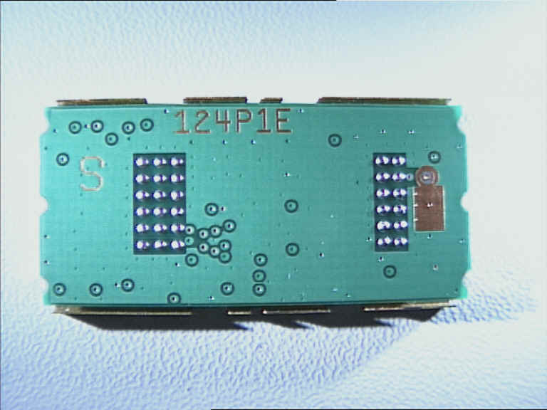
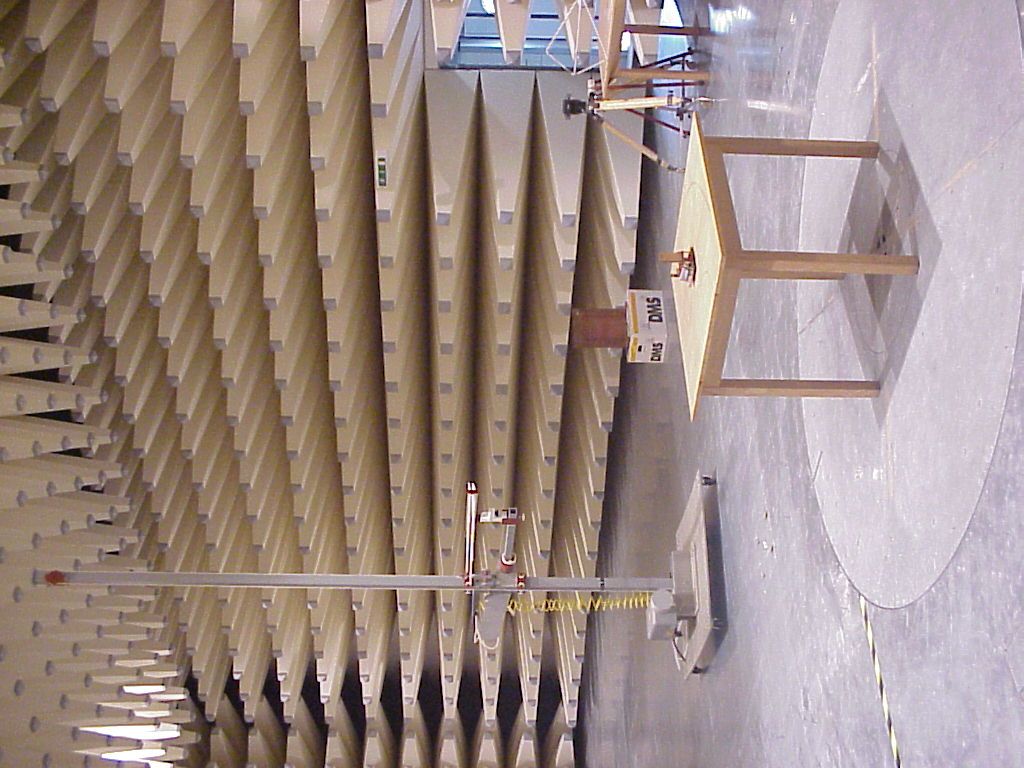
CETECOM ICT Services GmbH Radio Satelite Communication Untertürkheimer Straße 6-10 . D-66117 SaarbrückenTelefon: +49 (0)681 598-9100Telefax: -9075 RSC11issue test report consist of 15 PagesPage 1 (15) Test report no.: 2_2060-B/00 FCC Part 15.247 8001001 ROANA 201 132 Akkreditiertes Prüflaboratorium DAR-Registriernummer: TTI-P-G 166/98-00 vom 18.09.98 CETECOM ICT Services GmbH Test report nr.: 2_2060-B/00Issue date: 22.03.2000Page 2 (15) Table of Contents 1 General information 1.1 Notes 1.2 Testing laboratory 1.3 Details of applicant 1.4 Application details 1.5 Test item 1.6 Test standards 2 Technical test 2.1 Summary of test results 2.2 Test report 1 General information 1.1 Notes The test results of this test report relate exclusively to the test item specified in 1.5. The CETECOM ICT Services GmbH does not assume responsibility for any conclusions and generalisations drawn from the test results with regard to other specimens or samples of the type of the equipment represented by the test item. The test report may only be reproduced or published in full. Reproduction or publication of extracts from the report requires the prior written approval of the CETECOM ICT Services GmbH. CETECOM ICT Services GmbH Test report nr.: 2_2060-B/00Issue date: 22.03.2000Page 3 (15) 1.2Testing laboratory CETECOM ICT Services GmbH 66117 Saarbrücken Untertürkheimer Straße 6 - 10 Deutschland Telefone: + 49 681 598 - 9100 Telefax : + 49 681 598 - 9075 E-mail : [email protected] Internet : www.cetecom.de Accredited testing laboratory DAR-registration number : TTI-P-G 166/98-00 vom 18.09.98 1.3Details of applicant Name : Ericsson Radio Systems BV Street : Nieuw Amsterdamsestraat 40 City : 7801 CA Emmen Country : The Netherlands Telephone : +31 591 637 777 Telefax : +31 591 632 001 Contact : Mr. Jens Lehmann Telephone : +31 591 637 777 1.4Application details Date of receipt of application : 14.03.2000 Date of receipt of test item : 21.03.2000 Date of test : 21.03.2000 1.5Test item Type of equipment : Bluetoothmodul Type designation: 8001001 (ROANA 201 132 ) Manufacturer:applicant Street: City: Country: Serial number:-.- Additional informations: : Frequency:2400.0 - 2483.5 Type of modulation:24M0FXD (FHSS) Number of channels :79 Antenna:+1,0 dBi antenna Power supply:3.3V DC Type of equipment:Temperature range : 0°C - +75°C 1.6Test standards: FCC Part 15 §15.247 CETECOM ICT Services GmbH Test report nr.: 2_2060-B/00Issue date: 22.03.2000Page 4 (15) 2 Technical test 2.1Summary of test results No deviations from the technical specification(s) were ascertained in the course of the tests performed. Technical responsibility for area of testing : 10.04.00RSC 8411 Berg DateSectionNameSignature Technical responsibility for area of testing : 10.04.00RSC8414Ames DateSectionNameSignature CETECOM ICT Services GmbH Test report nr.: 2_2060-B/00Issue date: 22.03.2000Page 5 (15) 2.2Testreport TEST REPORT Testreport no. : 2_2060-B/00 CETECOM ICT Services GmbH Test report nr.: 2_2060-B/00Issue date: 22.03.2000Page 6 (15) TEST REPORT REFERENCE LIST OF MEASUREMENTS ParagraphPARAMETER TO BE MEASUREDPAGE Transmitter parameters § 15.247 (a)(1) 20 dB Bandwidth7 § 15.247 (b)(1) Maximum peak output power8 § 15.247 (c)(1) Emission limitations 9 Receiver parameters § 15.209Spurious radiations - Radiated10 Test equipment listing11 Photographs of the equipment13 CETECOM ICT Services GmbH Test report nr..: 2_2060-B/00Issue Date: 22.03.2000Page 7 (15) Equipment under test : 8001001 (ROANA 201 132) Ambient temperature : 23° °° °C Relative humidity : 34% REFERENCE NUMBER(S) OF TEST EQUIPMENT USED (for reference numbers see test equipment listing) 17 - 24 20 dB BANDWIDTHSUBCLAUSE § 15.247 (a)(1) TEST CONDITIONS20 dB BANDWIDTH ( kHz ) Frequency (MHz)240224422482 T nom ( 23 )° °° °C V nom ( 1.25 )V769838963 Measurement uncertainty±3dB LIMIT SUBCLAUSE §15.247(a) (1) (ii) Occupied bandwith shall not exceed 1000 kHz CETECOM ICT Services GmbH Test report nr..: 2_2060-B/00Issue Date: 22.03.2000Page 8 (15) Equipment under test : 8001001 (ROANA 201 132) Ambient temperature : 23° °° °C Relative humidity : 34% REFERENCE NUMBER(S) OF TEST EQUIPMENT USED (for reference numbers see test equipment listing) 17 – 24 MAXIMUM PEAK OUTPUT POWERSUBCLAUSE § 15.247 (b) (1) TEST CONDITIONSMAXIMUM PEAK OUTPUT POWER (W) Frequency (MHz)240224422482 T nom ( 23 )° °° °C V nom ( 1.25 )V0.001110.001180.00110 Maximum deviation from output power under extreme test conditions (dBc) -0.67-1.0-0.9 Measurement uncertainty±3dB LIMIT SUBCLAUSE § 15.247 (b) (1) Frequency rangeRF power output 2400-2483.5 MHz / 5725 – 5850 MHz1.0 Watt CETECOM ICT Services GmbH Test report nr..: 2_2060-B/00Issue Date: 22.03.2000Page 9 (15) Equipment under test : 8001001 (ROANA 201 132) Ambient temperature : 23° °° °C Relative humidity : 34% REFERENCE NUMBER(S) OF TEST EQUIPMENT USED (for reference numbers see test equipment listing) 17 - 24 EMISSION LIMITATIONS (Transmitter)SUBCLAUSE § 15.247 (c) (1) EMISSION LIMITATIONS f (MHz) polari- zation amplitude of emission (dBm) limit max. allowed emmision power actual attenuation below frquency of operation (dB) results 2402vertical+0.4630.0 dBm-Operating frequency 4804vertical-54.29-20 dBc54.75complies > 5000verticalno peak found -20 dBc-complies 2440vertical+0.7230 dBm-Operating frequency 4880vertical-53.17-20 dBc53.89complies > 5000verticalno peak found -20dBc-complies 2480vertical+0.4230 dBmOperating frequency 4960vertical-52.27-20 dBc52.69complies > 5000verticalno peak found -20 dBc-complies Measurement uncertainty± 3dB LIMITSSUBCLAUSE § 15.247 (c) In any 100 kHz bandwidth outside the frequency band at least 20dB below the highest level of the desired power. In addition, radiated emissions which fall in the restricted bands, as defined in §15.205(a), must also comply with the radiated emission limits specified in §15.209(a) (see §15.205(c)). CETECOM ICT Services GmbH Test report nr..: 2_2060-B/00Issue Date: 22.03.2000Page 10 (15) Equipment under test…
Text truncated - open the document above for the full version.
Test Report
Ericssonwide Internal INFORMATION1 (7) Prepared (also subject responsible if other)No. EMN/ERH/TA Erwin Spits Uen ApprovedCheckedDateRevReference 10-5-00PA1 Additional information for the FCC approval process Abstract. This document co ntains plots that are needed for approval of the Barney module by the FCC. Ericssonwide Internal INFORMATION2 (7) Prepared (also subject responsible if other)No. EMN/ERH/TA Erwin Spits Uen ApprovedCheckedDateRevReference 10-5-00PA1 1 Channel spacing. “ Capture and submit a plot from a spectrum analyser showing the seperation between the peaks of the adjacent channels.” Figure 1 Channel spacing. This sweep was made over a span of 10MHz to show more detail. In fig. 3 the entire band is seen and there from also the 1MHz channel spacing can be derived. UNCAL VBW 10 kHz RBW 200 kHz 1 MHz/Span 10 MHzCenter 2.442 GHz 1MA1MAX SWT 10 ms RF Att 40 dB Ref Lvl 10 dBm Ref Lvl 10 dBmUnit dBm A -90 -80 -70 -60 -50 -40 -30 -20 -10 0 10 11 Delta 1 [T1] 0.02 dB 1.00200401 MHz Date: 10.MAY.2000 10:29:01 Ericssonwide Internal INFORMATION3 (7) Prepared (also subject responsible if other)No. EMN/ERH/TA Erwin Spits Uen ApprovedCheckedDateRevReference 10-5-00PA1 2 Hopping frequencies. “Capture and submit a plot or plots as necessary having sufficient detail to permit observation that the device is indeed hopping to the required number of individual channels.” 79 channels (fig 2.) “For a hybrid system the number of channels required to meet the processing gain requirement should be shown.” 32 channels (fig 3.) Figure 2. 79 hopping channels A * 2SA2VIEW 1VIEW 2VIEW SWT 100 ms UNCAL 1MA 2SA VBW 1 kHz RBW 200 kHz Span 100 MHzCenter 2.442 GHz10 MHz/ Unit dBm A RF Att 40 dB Ref Lvl 10 dBm Ref Lvl 10 dBm -90 -80 -70 -60 -50 -40 -30 -20 -10 0 10 Date: 10.MAY.2000 12:47:09 Ericssonwide Internal INFORMATION4 (7) Prepared (also subject responsible if other)No. EMN/ERH/TA Erwin Spits Uen ApprovedCheckedDateRevReference 10-5-00PA1 The Blue line in fig 2 shows a module hopping according the Europ/US hopping sequence. It therefore shows 79 channels. The spectrum analyser was set in a max hold function. To show that the system is really hopping, the module was not set to another state, only the spectrum analyser was set into an averaging mode. The result is the red line. Conclusio n can be made that since in max ho ld the entire band is filled with carriers and in averaging mode (200x) almost no power in band is seen, the system must be hopping. (This measurement can be reproduced by just making a co nnectio n between 2 devices and looking at the spectrum.) Figure 3 Europe/US channel numbers. This figure shows the full hopping sequence for Europe and the US. 79 channels can be seen. * 1MA1VIEW VBW 10 kHz RBW 200 kHz SWT 200 s 10 MHz/Span 100 MHzCenter 2.442 GHz RF Att 40 dB Ref Lvl 10 dBm Ref Lvl 10 dBmUnit dBm A -90 -80 -70 -60 -50 -40 -30 -20 -10 0 10 Date: 10.MAY.2000 10:11:52 Ericssonwide Internal INFORMATION5 (7) Prepared (also subject responsible if other)No. EMN/ERH/TA Erwin Spits Uen ApprovedCheckedDateRevReference 10-5-00PA1 Figure 4 Limited channel numbers inquiry mode 32 Figure 5 Limited channel numbers page mode 32 1MA1VIEW SWT 10 ms VBW 50 kHz RBW 500 kHz 10 MHz/Span 100 MHzCenter 2.442 GHz RF Att 40 dB Ref Lvl 10 dBm Ref Lvl 10 dBmUnit dBm A -90 -80 -70 -60 -50 -40 -30 -20 -10 0 10 Date: 10.MAY.2000 10:22:07 1MA1MAX SWT 10 ms VBW 50 kHz RBW 500 kHz 10 MHz/Span 100 MHzCenter 2.442 GHz RF Att 40 dB Ref Lvl 10 dBm Ref Lvl 10 dBmUnit dBm A -90 -80 -70 -60 -50 -40 -30 -20 -10 0 10 Date: 10.MAY.2000 10:23:41 Ericssonwide Internal INFORMATION6 (7) Prepared (also subject responsible if other)No. EMN/ERH/TA Erwin Spits Uen ApprovedCheckedDateRevReference 10-5-00PA1 3 Dwell time. “Submit a plot of the dwell time for a hopping frequency over a 30 sec period.” The spectrum analyser was first set into zero span, with a sweep time of 30 seconds. This plot shows how often a frequency is used in a 30 second time period. The seco nd plot shows the packet used. The longest possible in a Bluetooth connection is 2.8 ms. The slots from figure 6 are the same slots as in fig 7 Figure 6 Dwell time of a single hopping freuqency. 88 occurrences x 2.8 ms = 246,4 ms (allowed is 400 ms) 1MA1VIEW VBW 2 kHz RBW 100 kHz 3 s/Center 2.442 GHz SWT 30 sUnit dBm A RF Att 40 dB Ref Lvl 10 dBm Ref Lvl 10 dBm -90 -80 -70 -60 -50 -40 -30 -20 -10 0 10 11 Delta 1 [T1] 0.00 dB 0.000000 s Date: 10.MAY.2000 10:33:50 Ericssonwide Internal INFORMATION7 (7) Prepared (also subject responsible if other)No. EMN/ERH/TA Erwin Spits Uen ApprovedCheckedDateRevReference 10-5-00PA1 Figure 7 Slot length 1MA1VIEW 10 ms/Center 2.442 GHz SWT 100 ms VBW 2 kHz RBW 100 kHz Unit dBm A RF Att 40 dB Ref Lvl 10 dBm Ref Lvl 10 dBm -90 -80 -70 -60 -50 -40 -30 -20 -10 0 10 1 1 Delta 1 [T1] 0.85 dB -2.404810 ms Date: 10.MAY.2000 10:38:25
Test Report
This is a screen hardcopy of the measurement result.
Test Report
Limited Internal 1 (13) Prepared (also subject responsible if other)No. EMN/ERH/TG R.H. Linde Uen Ap…
Text truncated - open the document above for the full version.
Contact Information
Applicant
Phil Inglis
Technical Contact
Cetecom b.v.b.a., MDPhillip M Inglis
[email protected]410-531-3439
14085 Howard Road · Dayton, Maryland · United States
Non-Technical Contact
Cetecom b.v.b.a., MDPhillip M Inglis
[email protected]4105313439
Technical Specifications
| # | Rule Parts | Frequency Range | Power Output |
|---|---|---|---|
| 1 | 15C | 2.40 GHz - 2.48 GHz | 1.00 mW |
Other Applications from Ericsson Radio Systems BV
CGK108-0
May 05, 1998CXX - Communications Rcvr for use w/ licensed Tx and CBs
Equipment Class
CXX - Communications Rcvr for use w/ licensed Tx and CBs
CGK108-1
Apr 21, 1998CXX - Communications Rcvr for use w/ licensed Tx and CBs
Equipment Class
CXX - Communications Rcvr for use w/ licensed Tx and CBsCGK2922
Apr 16, 1997CXX - Communications Rcvr for use w/ licensed Tx and CBs
Equipment Class
CXX - Communications Rcvr for use w/ licensed Tx and CBsCGK087
Nov 26, 1996DCD - Part 15 Low Power Transmitter Below 1705 kHz
Equipment Class
DCD - Part 15 Low Power Transmitter Below 1705 kHzCGK311
Jun 03, 1996Location Transmitter
Equipment Class
DCD - Part 15 Low Power Transmitter Below 1705 kHz