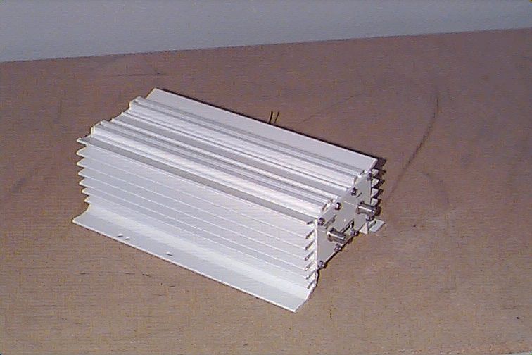
CI32278TR2278 Transverter
Conifer Corporation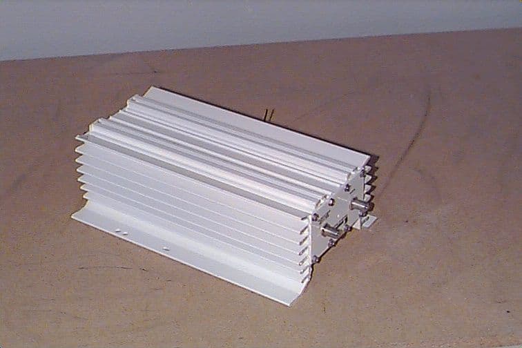
Click to zoom
Application Details
- Equipment Class
- AMP - Amplifier
- Date of Grant
- Dec 16, 1999
- Application Purpose
- Original Equipment
- Date of Application
- Aug 31, 1999
- Equipment Note
- TR2278 Transverter
- Frequency Range
- 2150.00000000 - 2162.00000000
- Company
- Conifer Corporation
- Country
- United States
Documents & Files
Document Text
Text extracted from the exhibit documents filed with the FCC. Open a document above to read the original.
Users Manual
CONIFER II ® WIRELESS TELECOMMUNICATION TECHNOLOGY Warning: Installation of Antenna near power lines is dangerous! Type certified for operation under Part 21.909. Ultraflex® System Must Be Professionally Installed. Ultraflex ® System Transverter Installation & Operator Manual Photo shows Transverter installed with 18dBi Microceptor, Model QD-2450. Optional 18dBi (Model 18T-2127) and 24dBi (Model 26T- 2127) available. Page 12. Ultraflex® Two-Way System Packing List (1) Response Antenna Options •QD-2450 •18T-2127 •26T-2127 (1) Transverter (1) Power Supply/Inserter (1) GPS Antenna (2) Transverter Mounting Brackets #726055 for inch pipe #726044 for 1-2 inch O.D. pipe (2) “L” Bolts #163155.2 Response Antenna Options QD-2450 (2) #6 x 1/2” Stainless Screws Model 26T-2127 FEED BOX (1) Feed assembly (1) Sub-reflector (1) #6 x 1/2” stainless screw (2) Stainless 1/4 x 20 hex nuts (2) Stainless lock washers (2) Stainless carriage bolts REFLECTOR BOX (2) Reflector halves (2) Stainless U-bolts (2) Mast clamps (1) Mounting "L" shaped bracket (4) Keps nuts (4) #8-32 machine screws (6) Stainless 1/4 x 20 hex nuts (6) Stainless lock washers (2) Stainless carriage bolts (1) Stainless flat plate washer Model 18T-2127 FEED BOX (1) Feed assembly (1) Sub-reflector (1) #6 x 1/2" stainless screw (2) Stainless 1/4 x 20 x 1" carriage bolts (2) Stainless 1/4 x 20 Hex nuts (2) Stainless 1/4" lock washers REFLECTOR BOX (1) Reflector (1) Mast clamp (1) Mounting "L" shaped bracket (1) Stainless U-bolt 1/4 x 20 x 2" (2) Stainless 1/4 x 20 Hex nuts (2) Stainless 1/4" lock washers (1) Stainless flat plate washer #1 #2 #3 Page 2. GPS Antenna GPS Port Antenna Port (located on side of transverter) Mounting Bracket “L” Bolt Figure 10 Bracket Chan- nels Input/Output -20dB Test Figure 9 0-20 dB Attn. Downstream To “Ant” To “Set” Figure 11 Figure 8 11. Connect the downlead cable to the input/output on the Transverter. (See Figure 9.) Page 11. 10. Mount the Transverter on the mast by sliding the mounting bracketsand “L” Bolts into the bracket channels on the backside of the Transverter. (See Figure 10.) 12. Run the downlead to the PS-0200 power supply connector labeled “To Ant”. (See Figure 11.) 13. Run a cable from the PS-0200 power supply connector labeled “To Set” to the set-top. (See Figure 11.) Antenna Output GPS Antenna GP-0100 Transverter TR-2278 Response Antenna QD-2450 Antenna Port (located on side of transverter) GPS Port Polarity Position INSTALLATION / ASSEMBLY with QD-2450 Response Antenna 1. Determine the polarity of the antenna. (See Figure 1.) NOTE: See labeling on the back of the QD-2450 antenna for horizontal and vertical polarity positioning. 2. Connect the QD-2450 antenna output to the antenna port on the side of the Transverter. (See Figure 1.) 3. Secure the transverter and antenna connection with a #6 stainless screw on each side of the Transverter. (See Figure 1.) 4. Connect the GPS Antenna to the GPS port on the Transverter. (See Figure 1.) NOTE: Warning! GPS Port Only - +5VDC output 0 VDC input maximum. Figure 1 #6 Stainless Screw (One on each side) V E R HOR Page 3. Figure 5 Mast Clamp U-Bolt Figure 6 Mast Clamp Tilt Holes Mast Clamp 6. Attach the feed on the front with 2 carriage bolts. Secure on the back with the lockwashers and nuts. (See Figure 4.). 7. Place the 2 mast clamps on the 2 U-bolts. (See Figure 6). Fasten the U-bolts on the “L” bracket with the 4 lockwashers and nuts (See Figure 5). NOTE: By eliminating 1 mast clamp and U-bolt, the optional fixed tilt holes provide eleva- tion in 10 0 increments. (Not recommended under high wind conditions.) (See Figure 6.) Use the flat plate washer on the adjustable tilt slot to secure the antenna to the required elevation. (See Figure 7.) Figure 7 Tilt Slot Page 10. 8. Connect the GPS Antenna to the GPS port on the Transverter. (See Figure 8) 9. Connect the 26T-2127 antenna output to the antenna port on the side of the Transverter. (See Figure 8) 6. Mount the complete unit on a 1-2” O.D. mast or on Conifer’s optional DS-1000 mount assembly. (See Figure 3.) 7. Connect the downlead cable to the input/output on the Transverter. (See Figure 4.) 8. Run the downlead to the PS-0200 power supply connector labeled “To Ant”. (See Figure 5.) 9. Run a cable from the PS-0200 power supply connector labeled “To Set” to the set-top. (See Figure 5.) 5. Slide the mounting brackets and “L” Bolts into the bracket channels on the backside of the Transverter. (See Figure 2.) Mounting Bracket “L” Bolt Figure 2 Input/Output -20dB Test Figure 3 0-20 dB Attn. Downstream To “Ant” To “Set” Figure 5 Bracket Chan- nels DS-1000 Mount Figure 4 Page 4. Figure 3 4. Place the “L” bracket on the back of the antenna. Insert two carriage bolts from the front (figure 4) to attach. Secure on the back with the lock washers and nuts. (See Figure 5). 5.Re-check the dipole feed assembly for the proper polarity. (See Figures 1 & 2). Figure 4 Sub-reflector Page 9. INSTALLATION / ASSEMBLY with 18T-2127 Response Antenna 1. Place the sub-reflector on the front of the feed and secure with the #6 x 1/2" stainless screw. (See Figure 1). 2. Determine the polarity of the antenna. (See figures 2 & 3). Figure 1 Sub-reflector Figure 2 Figure 3 Horizontal Polarity Vertical Polarity Page 5. 1. Assemble the two halves inserting the 4 #8-32 machine screws through the front. Secure with the keps nuts on the back. (See Figure 3). Vertical Polarity Figure 2 Note: Loosely tighten all hardware until completely assembled and then tighten securely. INSTALLATION / ASSEMBLY with 26T-2127 Response Antenna Horizontal Polarity: Refer to (figure 1) for proper feed alignment. Vertical Polarity: Refer to (figure 2) for proper feed alignment. 3. Determine the polarity of the antenna. (See Figures 1 & 2). 2. Place the sub-reflector on the front of the feed and secure with the #6 x 1/2” stainless screw. (See Figure 4). Figure 1 Horizontal Polarity Page 8. Model 18T-2127 Model 18T-2127 Model 18T-2127 Mast Clamp U-Bolt Figure 6 “L” B…
Text truncated - open the document above for the full version.
ID Label/Location Info
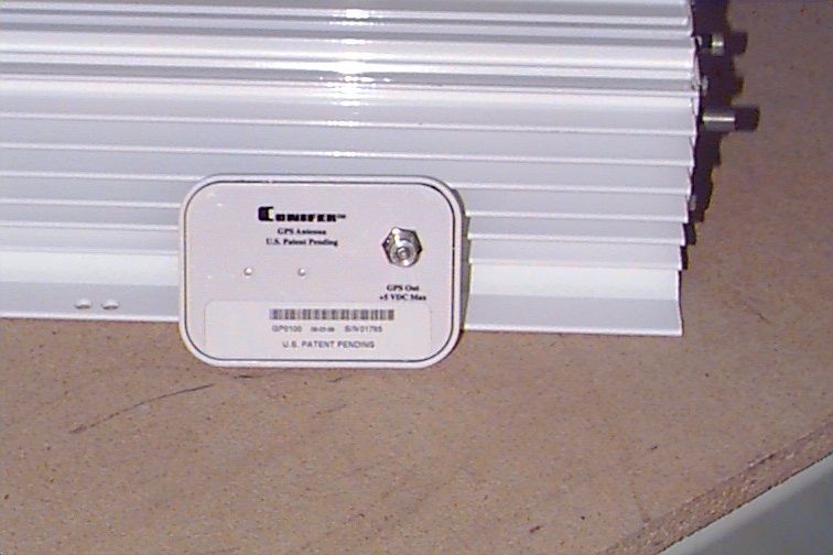
Sample FCC ID Number Material: 2 mil clear polyester w/794 adhesive laminated with 1.5 mil clear over laminate. Silver stock. Font: .1” high Sans serif End Plate
Test Report
Master: ktlDPT21SUBKmds Date: August 26, 1999 KTL Test Report:9L0114R Applicant:Conifer Corporation Equipment Under Test: (E.U.T.)TR2278 Signal Transverter FCC ID:CI32278 In Accordance With:FCC PART 21, Subpart K, FCC PART 74 Multipoint Distribution Service Tested By:KTL Dallas Inc. 802 N. Kealy Lewisville, Texas 75057-3136 Authorized By: Tom Tidwell, RF Group Manager Date: Total Number of Pages:1 KTL DallasFCC PART 21, SUBPART K MULTIPOINT DISTRIBUTION SERVICE PROJECT NO.: 9L0114R EQUIPMENT: TR2278 Transverter FCC ID: CI32278 Page 2 of 95 Table of Contents Table of Contents............................................................................................................................ 2 Section 1. Summary of Test Results....................................................................................... 3 Section 2. General Equipment Specification........................................................................... 5 Section 3. RF Power Output.................................................................................................. 10 Section 4. Occupied Bandwidth............................................................................................ 11 Section 5. Spurious Emissions at Antenna Terminals........................................................... 59 Section 6. Field Strength of Spurious.................................................................................... 78 Section 7. Frequency Stability............................................................................................... 80 Section 8. Test Equipment List............................................................................................. 81 Section 8. Test Equipment List............................................................................................. 82 Section 9. Test Setup Photos................................................................................................. 83 ANNEX A - TEST DETAILS...................................................................................................... A1 ANNEX B - TEST DIAGRAMS................................................................................................. B1 KTL DallasFCC PART 21, SUBPART K MULTIPOINT DISTRIBUTION SERVICE PROJECT NO.: 9L0114R EQUIPMENT: TR2278 Transverter FCC ID: CI32278 Page 3 of 95 Section 1.Summary of Test Results Manufacturer:Conifer Corporation Model No.:TR2278 Serial No.:NONE General:All measurements are traceable to national standards. These tests were conducted on a sample of the equipment for the purpose of demonstrating compliance with FCC Part 21, Subpart K and Part 74. New SubmissionProduction Unit Class II Permissive ChangePre-Production Unit THIS TEST REPORT RELATES ONLY TO THE ITEM(S) TESTED. THE FOLLOWING DEVIATIONS FROM, ADDITIONS TO, OR EXCLUSIONS FROM THE TEST SPECIFICATIONS HAVE BEEN MADE. See “ Summary of Test Data”. NVLAP LAB CODE: 100426-0 TESTED BY: Tom TidwellDATE: KTL Dallas Inc. authorizes the above named company to reproduce this report provided it is reproduced in its entirety and for use by the company’s employees only. Any use which a third party makes of this report, or any reliance on or decisions to be made based on it, are the responsibility of such third parties. KTL Dallas Inc. accepts no responsibility for damages, if any, suffered by any third party as a result of decisions made or actions based on this report. This report applies only to the items tested. KTL DallasFCC PART 21, SUBPART K MULTIPOINT DISTRIBUTION SERVICE PROJECT NO.: 9L0114R EQUIPMENT: TR2278 Transverter FCC ID: CI32278 Page 4 of 95 Summary Of Test Data NAME OF TESTPARA. NO.SPEC.MEAS.RESULT RF Power Output2.104633dBW EIRPComplies Occupied Bandwidth2.104921.908 (b) MaskComplies Spurious Emissions @ Antenna Terminals2.1051-60 dBcComplies Field Strength of Spurious Radiation2.1053-60 dBcComplies Frequency Stability2.1055 ± 1 kHz N/AN/A Footnotes: Frequency stability was not measured since the EUT uses a common oscillator for frequency conversion which oscillator is synchronized to the GPS timing signal. KTL DallasFCC PART 21, SUBPART K MULTIPOINT DISTRIBUTION SERVICE PROJECT NO.: 9L0114R EQUIPMENT: TR2278 Transverter FCC ID: CI32278 Page 5 of 95 Section 2.General Equipment Specification Max. Power Input: QPSK +10 dBm 16 QAM +7 dBm Frequency Range: 2150 – 2162 MHz MDS band Type(s) of Modulation: F3E (Voice) F1DF2DD7W (QAM) G7W (QPSK) Emission Designator: QPSK 100KG7W, 200KG7W, 400KG7W, 640KG7W, 800KG7W, 1M60G7W, 1M93G7W, 2M10G7W 16QAM 200KD7W, 400KD7W, 800KD7W, 1M60D7W, 3M20D7W Output Impedance: 50 ohms Gain: 20 dB (fixed) RF Power Output Rated:Per Carrier: +27 dBm nominal (QPSK), +24 dBm nominal(16QAM) Composite: Not Applicable Duty Cycle: Continuous Channel Spacing: N/A Operator Selection Of Operating Frequency: Not selectable by user Power Output Adjustment Capability: Not adjustable by user. Description of Modulation(s): QPSK Data Source: Pseudo-random bit source Symbol rate: Variable Filter: COS/0.25 Coding: None 16QAM Data Source: Pseudo-random bit source Symbol rate: Variable Filter: COS/0.25 Coding: None KTL DallasFCC PART 21, SUBPART K MULTIPOINT DISTRIBUTION SERVICE PROJECT NO.: 9L0114R EQUIPMENT: TR2278 Transverter FCC ID: CI32278 Page 6 of 95 QPSK Modulation Symbol Rate (ksps) Useable Bandwidth (kHz) Maximum Input Level (dBm) RF Output (dBm) 128100+10+27.0 160200+10+27.0 320400+9+26.4 512640+9+27.0 640800+9+27.0 12801600+9+27.0 15441930+9+27.0 20482100+8+26.0 25603200+8+26.0 16QAM Symbol Rate (ksps) Useable Bandwidth (kHz) Maximum Input Level (dBm) RF Output (dBm) 160200+7+24.0 320400+6+23.5 640800+6+23.5 12801600+6+23.5 25603200+6+23.5 KTL DallasFCC PART 21, SUBPART K MULTIPOINT DISTRIBUTION SERVICE PROJECT NO.: 9L0114R EQUIPMENT: TR2278 Transverter FCC ID: CI32278 Page 7 of 95 Description of Modifications For Class II Permissive Change KTL DallasFCC PART 21, SUBPART K MULTIPOINT DISTRIBUTION SERVICE PROJECT NO.: 9L0114R EQUIPMENT: TR2278 Transvert…
Text truncated - open the document above for the full version.
Test Report
Master: ktlDPT21SUBKmds Date: August 26, 1999 KTL Test Report:9L0114R Applicant:Conifer Corporation Equipment Under Test: (E.U.T.)TR2278 Signal Transverter FCC ID:CI32278 In Accordance With:FCC PART 21, Subpart K, FCC PART 74 Multipoint Distribution Service Tested By:KTL Dallas Inc. 802 N. Kealy Lewisville, Texas 75057-3136 Authorized By: Tom Tidwell, RF Group Manager Date:8/31/99 Total Number of Pages:1 KTL DallasFCC PART 21, SUBPART K MULTIPOINT DISTRIBUTION SERVICE PROJECT NO.: 9L0114R EQUIPMENT: TR2278 Transverter FCC ID: CI32278 Page 2 of 96 Table of Contents Table of Contents............................................................................................................................ 2 Section 1. Summary of Test Results....................................................................................... 3 Section 2. General Equipment Specification........................................................................... 5 Section 3. RF Power Output.................................................................................................. 10 Section 4. Occupied Bandwidth............................................................................................ 11 Section 5. Spurious Emissions at Antenna Terminals........................................................... 59 Section 6. Field Strength of Spurious.................................................................................... 78 Section 7. Frequency Stability............................................................................................... 81 Section 8. Test Equipment List............................................................................................. 82 Section 8. Test Equipment List............................................................................................. 83 Section 9. Test Setup Photos................................................................................................. 84 ANNEX A - TEST DETAILS...................................................................................................... A1 ANNEX B - TEST DIAGRAMS................................................................................................. B1 KTL DallasFCC PART 21, SUBPART K MULTIPOINT DISTRIBUTION SERVICE PROJECT NO.: 9L0114R EQUIPMENT: TR2278 Transverter FCC ID: CI32278 Page 3 of 96 Section 1.Summary of Test Results Manufacturer:Conifer Corporation Model No.:TR2278 Serial No.:NONE General:All measurements are traceable to national standards. These tests were conducted on a sample of the equipment for the purpose of demonstrating compliance with FCC Part 21, Subpart K and Part 74. New SubmissionProduction Unit Class II Permissive ChangePre-Production Unit THIS TEST REPORT RELATES ONLY TO THE ITEM(S) TESTED. THE FOLLOWING DEVIATIONS FROM, ADDITIONS TO, OR EXCLUSIONS FROM THE TEST SPECIFICATIONS HAVE BEEN MADE. See “ Summary of Test Data”. NVLAP LAB CODE: 100426-0 TESTED BY: Tom TidwellDATE: 11 – 15 August, 1999 KTL Dallas Inc. authorizes the above named company to reproduce this report provided it is reproduced in its entirety and for use by the company’s employees only. Any use which a third party makes of this report, or any reliance on or decisions to be made based on it, are the responsibility of such third parties. KTL Dallas Inc. accepts no responsibility for damages, if any, suffered by any third party as a result of decisions made or actions based on this report. This report applies only to the items tested. KTL DallasFCC PART 21, SUBPART K MULTIPOINT DISTRIBUTION SERVICE PROJECT NO.: 9L0114R EQUIPMENT: TR2278 Transverter FCC ID: CI32278 Page 4 of 96 Summary Of Test Data NAME OF TESTPARA. NO.SPEC.MEAS.RESULT RF Power Output2.104633dBW EIRP+18 dBWComplies Occupied Bandwidth2.104921.908 (b) MaskPlots 1 - 47Complies Spurious Emissions @ Antenna Terminals2.1051-60 dBcPlots 48 - 65Complies Field Strength of Spurious Radiation2.1053-60 dBc-63 dBcComplies Frequency Stability2.1055 ± 1 kHz N/AN/A Footnotes: Frequency stability was not measured since the EUT uses a common oscillator for frequency conversion which oscillator is synchronized to the GPS timing signal. KTL DallasFCC PART 21, SUBPART K MULTIPOINT DISTRIBUTION SERVICE PROJECT NO.: 9L0114R EQUIPMENT: TR2278 Transverter FCC ID: CI32278 Page 5 of 96 Section 2.General Equipment Specification Max. Power Input: QPSK +10 dBm 16 QAM +7 dBm Frequency Range: 2150 – 2162 MHz MDS band Type(s) of Modulation: F3E (Voice) F1DF2DD7W (QAM) G7W (QPSK) Emission Designator: QPSK 100KG7W, 200KG7W, 400KG7W, 640KG7W, 800KG7W, 1M60G7W, 1M93G7W, 2M10G7W 16QAM 200KD7W, 400KD7W, 800KD7W, 1M60D7W, 3M20D7W Output Impedance: 50 ohms Gain: 20 dB (fixed) RF Power Output Rated:Per Carrier: +27 dBm nominal (QPSK), +24 dBm nominal(16QAM) Composite: Not Applicable Duty Cycle: Continuous Channel Spacing: N/A Operator Selection Of Operating Frequency: Not selectable by user Power Output Adjustment Capability: Not adjustable by user. Description of Modulation(s): QPSK Data Source: Pseudo-random bit source Symbol rate: Variable Filter: COS/0.25 Coding: None 16QAM Data Source: Pseudo-random bit source Symbol rate: Variable Filter: COS/0.25 Coding: None KTL DallasFCC PART 21, SUBPART K MULTIPOINT DISTRIBUTION SERVICE PROJECT NO.: 9L0114R EQUIPMENT: TR2278 Transverter FCC ID: CI32278 Page 6 of 96 QPSK Modulation Symbol Rate (ksps) Useable Bandwidth (kHz) Maximum Input Level (dBm) RF Output (dBm) 128100+10+27.0 160200+10+27.0 320400+9+26.4 512640+9+27.0 640800+9+27.0 12801600+9+27.0 15441930+9+27.0 20482100+8+26.0 25603200+8+26.0 16QAM Symbol Rate (ksps) Useable Bandwidth (kHz) Maximum Input Level (dBm) RF Output (dBm) 160200+7+24.0 320400+6+23.5 640800+6+23.5 12801600+6+23.5 25603200+6+23.5 KTL DallasFCC PART 21, SUBPART K MULTIPOINT DISTRIBUTION SERVICE PROJECT NO.: 9L0114R EQUIPMENT: TR2278 Transverter FCC ID: CI32278 Page 7 of 96 Description of Modifications For Class II Permissive Change KTL DallasFCC PART 21, SUBPART K MULTIPOINT DI…
Text truncated - open the document above for the full version.
Contact Information
Technical Contact
KTL Dallas, Inc.Tom N Tidwell
[email protected]972-436-9600
802 N. Kealy · Lewisville, Texas · United States
Non-Technical Contact
Tom TidwellTom N Tidwell
[email protected]972-436-9600
Test Firm
Nemko Dallas, Inc.Michael Cantwell
Technical Specifications
| # | Rule Parts | Frequency Range | Power Output | Emission | Tolerance |
|---|---|---|---|---|---|
| 2 | 21,74 | 2.15 GHz - 2.16 GHz | 500.00 mW | DXW | Amp |