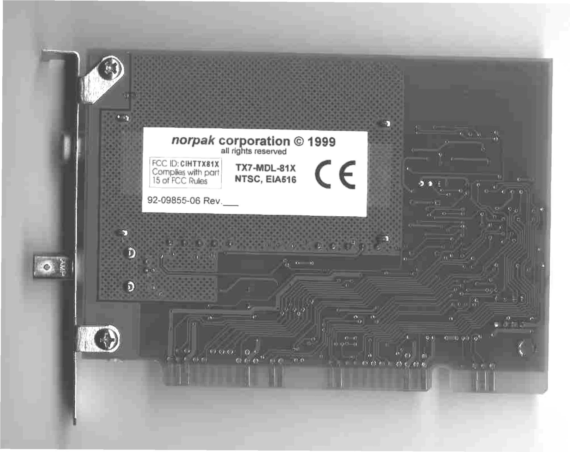
CIHTTX81X
Norpak Corporation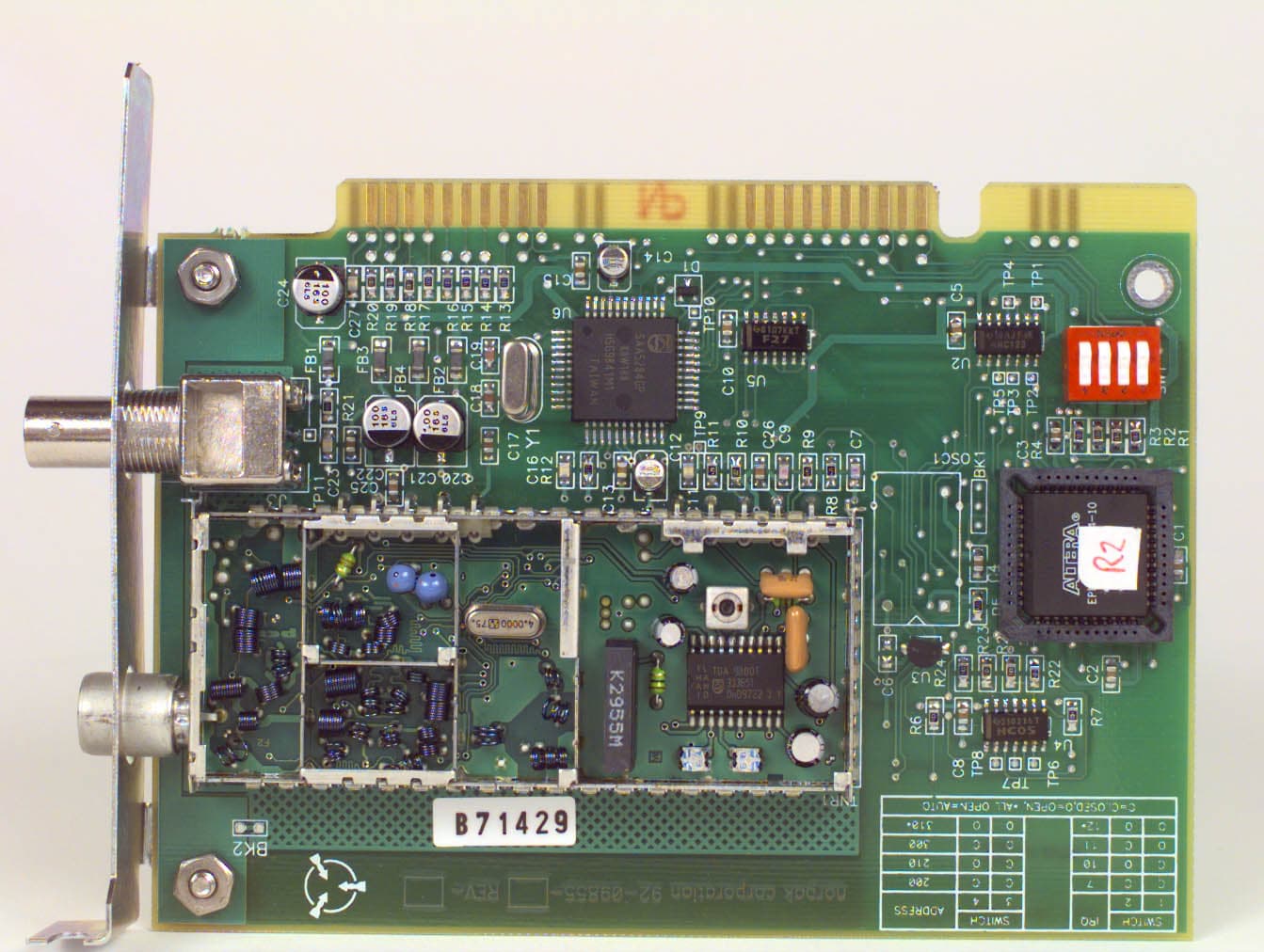
Click to zoom
Application Details
- Equipment Class
- JBP - Part 15 Class B Computing Device Peripheral
- Date of Grant
- Jul 01, 1999
- Application Purpose
- Original Equipment
- Date of Application
- May 31, 1999
- Company
- Norpak Corporation
- Country
- Canada
Documents & Files
Document Text
Text extracted from the exhibit documents filed with the FCC. Open a document above to read the original.
Users Manual
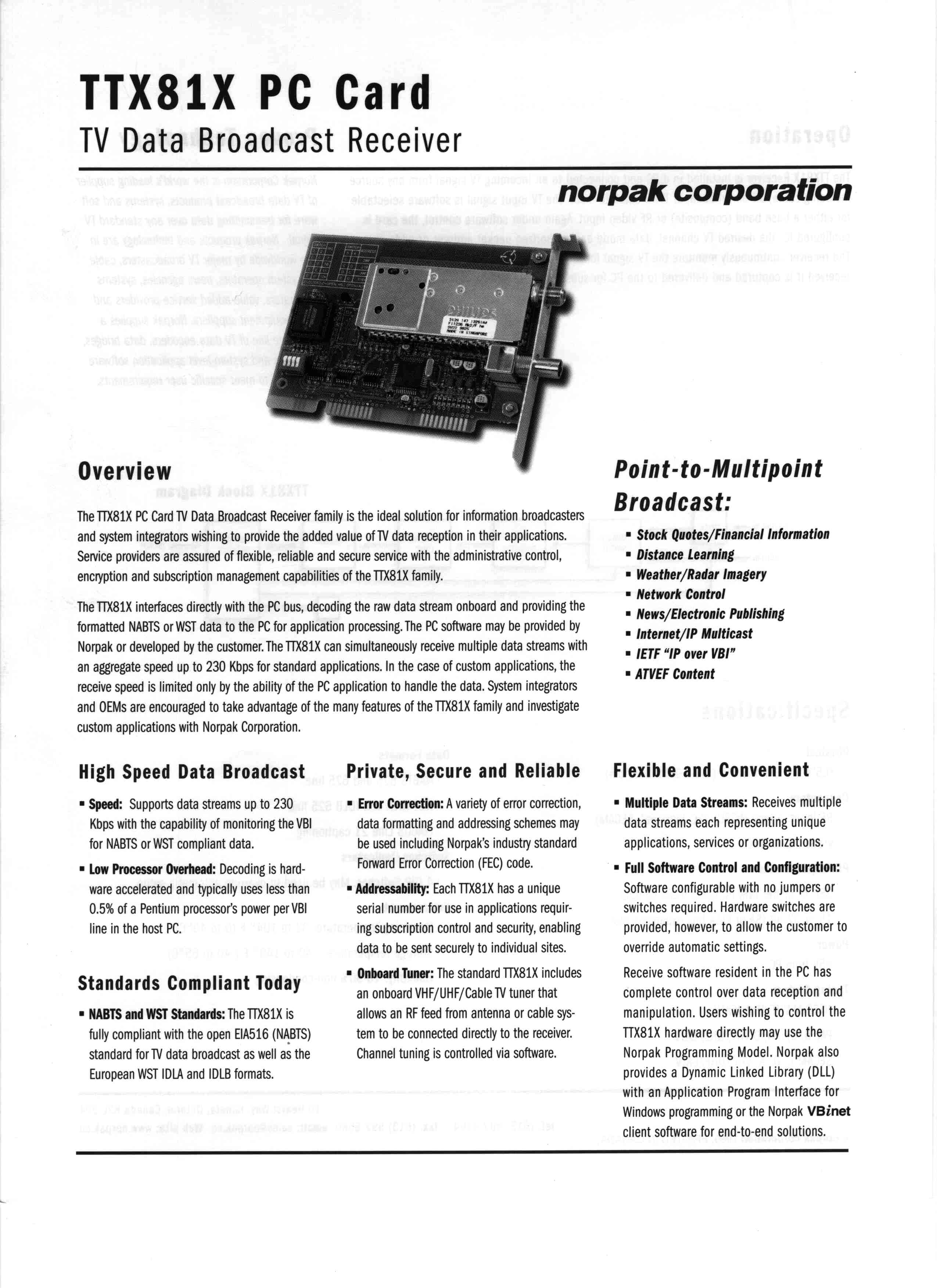
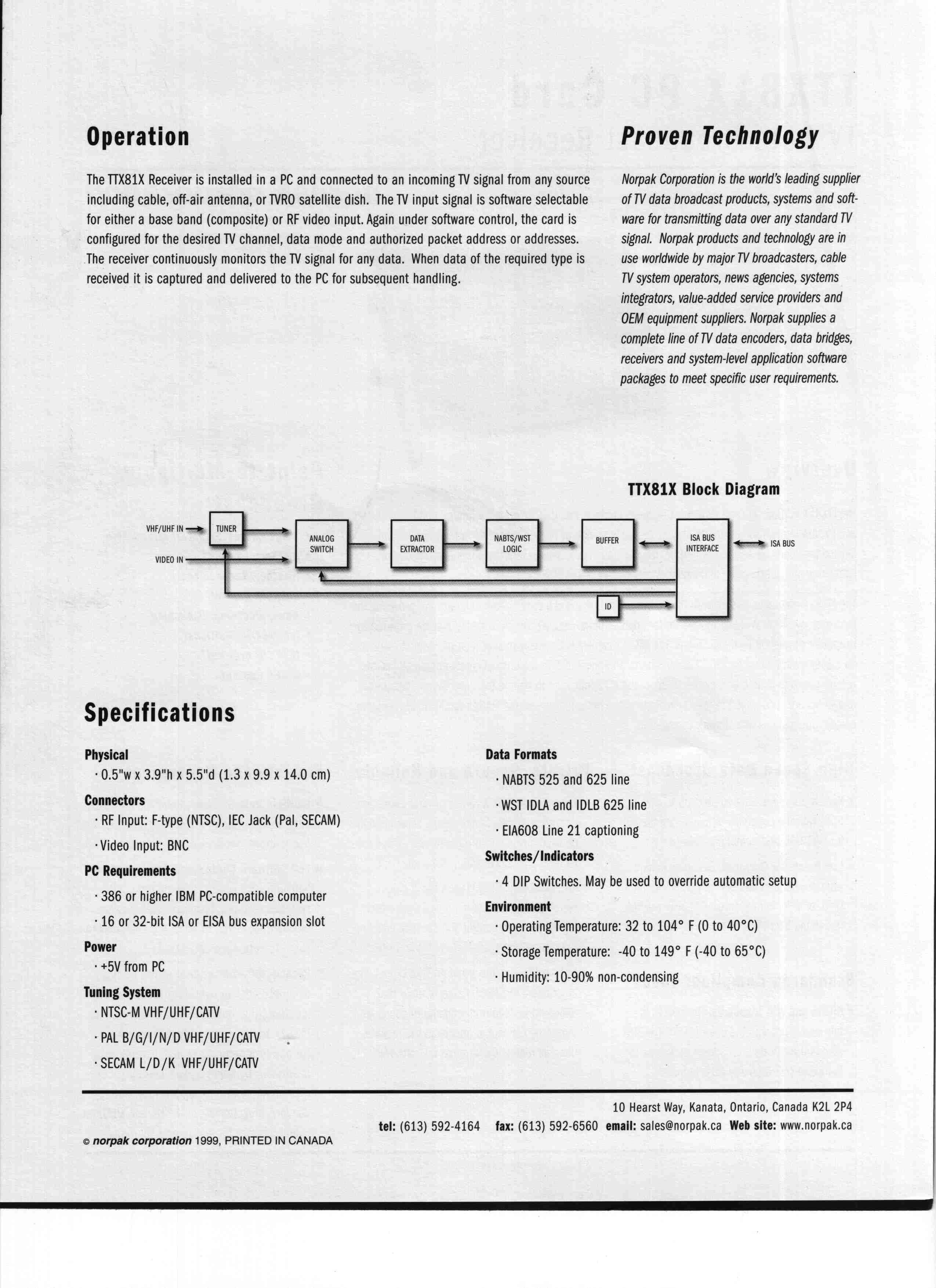
Connecting Video There are two types of video signal which can be used with the TTX81X. The “RF in” jack will accept a VHF/UHF signal such as you would obtain from either a cable outlet or a rooftop antenna for local broadcast. A threaded (type F) jack is used on the “North American” model (TTX815); an IEC aerial jack is used on the “European” model (TTX816). If you have an RF signal, connect it as shown below. If it is the threaded type, tighten it fully using your fingers. The “Video In” jack will accept a composite video signal such as you would obtain from the “video out” jack of a satellite receiver, component tuner or VCR. This jack is a reliable BNC type; if your video signal source uses another type of jack (for example, phono), you will need an adaptor to connect it to the TTX81X. If you have a video signal, connect it as shown below. You are now ready to install and use your application software. To proceed, refer to the manual supplied with the software. norpak corporation Telephone: 613-592-4164. Fax: 613-592-6560 web: http://www.norpak.ca Document 85-098xx-01, Revision A norpak corporation TTX81X TV Data Receiver Installation Guide Introduction This guide describes how to install the TTX81X TV Data Receiver in your computer, how to connect the video signal to it, and how to check that it operates properly in your computer. Once you have completed these steps, you will be ready to install application software to work with the TTX81X. Please follow these steps carefully, to ensure a successful installation. Information to User The following warning is provided in compliance with the regulations of the United States Federal Communications Commission (FCC): This equipment has been tested and found to comply with the limits for a Class B digital device, pursuant to Part 15 of the FCC Rules. These limits are designed to provide reasonable protection against harmful interference in a residential installation. This equipment generates, uses and can radiate radio frequency energy and, if not installed and used in accordance with the instructions, may cause harmful interference to radio communications. However, there is no guarantee that interference will not occur in a particular installation. If this equipment does cause harmful interference to radio or television reception, which can be determined by turning the equipment off and on, the user is encouraged to try to correct the interference by one or more of the following measures: CReorient or relocate the receiving antenna. CIncrease the separation between the equipment and receiver. CConnect the equipment into an outlet on a circuit different from that to which the receiver is connected. CConsult the dealer or an experienced radio/TV technicain for help. Changes or modifications not expressly approved by Norpak Corporation could void the user's authority to operate the equipment. System Requirements To use the TTX81X, you need a computer with a vacant 16-bit ISA slot, and Windows 95, 98 or NT. Installation 1.With the power off and the power cord unplugged, remove the cover from your computer, following the manufacturer’s instructions. 2.Locate an unused “16-bit ISA slot” in the computer. If you are unsure what this means, look closely at the computer’s bus connectors. There is only one type which will accept the TTX81X; it will not fit in other connectors such as “PCI”. If there are 2 or more empty ISA slots, try to leave one slot vacant on each side of the TTX81X; this will ensure the best possible data reception. 3.Remove the blank mounting bracket from the selected slot, and retain the screw for later use. 4.Ensure that the “DIP switches” on the TTX81X are all in the OPEN position, which is how they are set at the factory. This is the best setting for most computers, since it allows the software to set up the card automatically. 5.Insert the TTX81X into the connector for the desired slot;. some pressure will normally be required. Align the hole in the upper edge of the TTX81X mounting bracket with the screw hole and replace the screw you removed in step 3. 6.Replace the computer’s cover and apply power. Testing After Windows is running, run the hardware test program as follows: click “Start”, then “Run”, then “Browse”. Locate the XXX program and run it. This will tell you whether the software was able to correctly identify the TTX81X card. If this was successful, proceed to Connecting Video. If not, follow the Troubleshooting instructions. Troubleshooting There are two common conditions which can cause the software to be unable to detect the TTX81X card: 1None of the addresses or interrupts which the TTX81X can use are available; or 2The setup address which the TTX81X uses to find an available address and IRQ is assigned to the PCI or other local bus. In case 1, you need to disable or reconfigure another device in the computer which is using one of the addresses needed by the TTX81X. Normally, this is done by using the PC’s setup facility or by setting switches or jumpers on the conflicting device. The TTX81X needs to use one of the following address ranges: 200-207, 210-217, 300-307, or 310- 317; it also needs one of the following interrupts: IRQ7, IRQ10, IRQ11 or IRQ12. Once you have reconfigured your computer so that at least one address range and one IRQ are available, repeat the test. In case 2, first try to use your computer’s setup facility to assign either address 2EF or 3EF to the ISA bus; if available, this may be in a menu with a name such as “PnP/Legacy” or “PCI/ISA”. If you are able to make this change, repeat the test. If not, you will need to turn off the computer by exiting from Windows and remove the computer cover. Then, use the DIP switches on the TTX81X to select a free address and IRQ. The switch settings are shown in a table printed on the card and are repeated below. Once you have set the switches, close the computer, apply power and repeat the test. SwitchSwitch IRQAddress 1234 ClosedClosed7ClosedClose…
Text truncated - open the document above for the full version.
Parts List/Tune Up Info
BOM, sorted by Item Number Parent: 92-09855-06 Rev AASSY,TTX816 PartRev Item DescriptionQty CommercialVendor Source NumberCode 10-40101-27017RES,FIXED,100/OHM,5%,1/10W,SMT1RMC1/10101J90442P R22 SEI ELECTRONICS INC. 10-40102-27010RES,FIXED,1KOHM,5%,1/10W,SMT1RMC1/10102J90442P R10 SEI ELECTRONICS INC. 10-40103-27011RES,FIXED,10KOHM,5%,1/10W,SMT15RMC1/10103J90442P R1-R4,R6,R7,R13-20,24 SEI ELECTRONICS INC. 10-40273-27012RES,FIXED,27KOHM,5%,1/10W,SMT1RMC1/10273J90442P R12 SEI ELECTRONICS INC. 10-40471-27013RES,FIXED,470/OHM,5%,1/10W,SMT2RMC1/10471J90442P R8,R9 SEI ELECTRONICS INC. 10-40472-27014RES,FIXED,4.7KOHM,5%,1/10W,SMT1RMC1/10472J90442P R5 SEI ELECTRONICS INC. 10-40621-27015RES,FIXED,620/OHM,5%,1/10W,SMT1RMC1/10621J90442P R11 SEI ELECTRONICS INC. 10-47508-26016RES,FIXED,75.0/OHM,1%,1/10W,SMT1RMC1/1075ROF90442P R21 SEI ELECTRONICS INC. 12-30101-01020CAP,CER,SMT,100PF,+/-10%,50V,08052C0805C101K5GAC90114P C7,C9 KEMET MFG. 12-30102-01026CAP,CER,SMT,1000PF,+/-10%,50V,08052C0805C102K5RAC90114P C25,26 KEMET MFG. 12-30103-01021CAP,CER,SMT,.01UF,+/-10%,50V,08054C0805C103K5RAC90114P C11,C16,C23,27 KEMET MFG. 12-30104-02022CAP,CER,SMT,.1UF,+/-10%50V,080511C0805C104K5RAC90114P C1-C5,C8,C10,C13,C15,C17,C22 KEMET MFG. 12-30220-01023CAP,CER,SMT,22PF,+/-10%,50V,08052C0805C220K5GAC90114P C18,C19 KEMET MFG. 12-35106-02024CAP,ALUM,SMT,10UF,20%,16V2GACE100M16V4X5.590439P C12,C14 CAL-CHIP 12-35107-01025CAP,ALUM,SMT,100UF,20%,16V3NACE101M16V6X5TR90444P C20,C21,C24 NIC COMPONENTS 13-00079-01031XTAL,12.0MHZ,HC-49/U,18PF,30PPM1A-12.000-1890481P Y1RALTRON 13-60038-01033FILTER,RF,FERRITE,SMT4FBY-32161190439P FB1-4 CAL-CHIP 14-00509-01040CONN,BNC,RECEP,PCB,RA,75OHM,METAL1BNC-000S11290435P J3 LEOCO CORPORATION 20-50007-01050SWITCH,DIP,PAK,ROCKER,4SWITCHES13-435640-590006P SW1 AMP MFG 28-13232-20092MHDW,SCREW,SS,6-32,PANPHIL,5/162SCREW,6X5/16,PANPHIL90078P GOULD MFG 28-22006-01093MHDW,WASHER,SS,6,LOCK,INT2WASHER,LOCK,NO690078P GOULD MFG 28-30632-01094MHDW,NUT,SS,6-32,HEX2NUT,6-3290032P ERIE MFG 31-07405-51060IC,CMOS,74HC05,HEX,INVERTER,OPENDRN1SN74HC05D90073P U4 TEXAS INSTRUMENTS MFG 31-07427-50061IC,TTL,74F27,NOR,TRIPLE,3IN,SOIC1SN74F27D90073P U5 TEXAS INSTRUMENTS MFG 31-33023-01062IC,ANA,SAA5284,DATA,EXTRACTOR1SAA5284GP90062P U6 PHILIPS MFG Wednesday, May 19, 1999Page 1 of2 Parent: 92-09855-06 Rev AASSY,TTX816 PartRev Item DescriptionQty CommercialVendor Source NumberCode 31-60053-01063IC,UP,SERIAL NUMBER,SILICON1DS240190446P U3 DALLAS SEMICONDUCTOR 31-74126-59064IC,CMOS,74AHC126,QUAD,BUS,BUF,SOIC1SN74AHC126D90073P U2 TEXAS INSTRUMENTS MFG 33-50914-01070DIODE,SIGNAL,1N914,SOT231MMBD914LT190052P D1 MOTOROLA MFG 35-09855-01A1DETAIL,TTX81X135-09855-0199999P NORPAK CORP 36-09856-01A80PROG,EPLD,TTX81X136-09856-0199999A U1 NORPAK CORP 41-09409-01A91BRACKET,TTX62X+,RF/VIDEO IN141-09409-0199999P BRACK1 NORPAK CORP 93-10010-01090ASSY,TUNER,PAL,B/G,SECAML,IEC,ADAP1FI1216MFMK2/HM/IEC90062P TNR1 PHILIPS MFG Wednesday, May 19, 1999Page 2 of 2
Schematics
NORPAK CONFIDENTIAL REVISION DATEENG.DRN.DESCRIPTIONREV. of norpak corporation and shall not be reproduced, copied or used as the basis for the manufacture or sale of apparatus without the written permission of norpak. These drawings and specifications are the property REF. DRG. OTHER APPR. MGR. ENG. DRFT. DES. DRN. ORDER CODENEXT ASSY. F.W. R.FITZGERALD. R.FITZGERALD. C SCALE TTX81X 85-09855-01 JAN28/99 COPYRIGHT 1999 KANATA,ONTARIO,CANADA LOGICS SHEET OF REV. 1 A TB1 CGND MT156 MT1 1 MTA 2 MTB BRACK1 41-09409-01 BRACKET,RF,VIDEO-IN +5V+5VIF RefDesValueDGND+5V U274AHC126714 U474HC05714 U574F27714 Power Table +5VT CGNDDGNDAGND +5VA 100μF C24 Ferrite Bead FB1 Ferrite Bead FB2 Ferrite Bead FB3 Ferrite Bead FB4 BK2 1213 U4:F 74HC05 D3 D4 D5 J1 ISA32_TTX81X_SM SYSRST SA0 SA1 SA2 SA3 SA4 SA5 SA6 IRQ12 IRQ11 IRQ10 IOR IOW B29 B21 B20 B14 B10 B3 B2 B1 A31 A30 A29 A28 B13 B31 A24 A23 A22 A11 A10 A9 A8 A7 A6 A5 A4 A3 A2 A26 A25 A27 J2 IRQ7 BCLK SA9 SA7 SA8 AEN IOCHRDY SD1 SD0 +5V SD2 SD3 SD4 SD5 SD6 SD7 FWAFIRST RELEASE 2
Schematics
SCALE C REV. NORPAK CONFIDENTIAL SHEET OF A 85-09855-01 9 10 11 8 U5:C 74F27 3 4 5 6 U5:B 74F27 BCLK SYSRST AEN SA4 SA5 SA6 SA7 SA8 SA9 +5V 7 GND 14 VCC 8 OUT OSC1 16.0Mhz NOT INSTALLED +5V C6 0.1μF BK1 IOR IOW SA0 SA1 SA2 SA3 +5V +5V 4.7K R5 2 DATA 1 GND 3 NC DS2401 U3 1 2 13 12 U5:A 74F27 1 2 3 4 8 7 6 5 SW1 R4 10K 10K R3 10K R2 10K R1 +5V C10 0.1μF 20 IRQ12EN 21 IRQ11EN 19 IRQ10EN 16 IRQ7EN 36 SA3 31 SA4 13 SA5 24 SA6 17 SA7 34 SA8 33 SA9_AEN 12 RESETDRV 43 SYSCLK 38 MIRQ1 18 MIRQ0 4 MAD1 37 MAD0 10 GND1 22 GND2 30 GND3 42 GND4 32 MODE 26 5284_CSL 14 5284_IOW 29 TSCK 8 SN_OUT 6 TDSA_OUT 27 TDSA_IN 2 SN_IN 44 IOW 25 IOR 5 SD0 40 SD1 39 SD2 41 SD3 7 SD4 1 SD5_7 28 SA0 9 SA1 11 SA2 3 VCC1 15 VCC2 23 VCC3 35 VCC4 EPM7032 36-09856-01 U1 C27 .01μF SD7 SD6 SD5 SD4 SD3 SD2 SD1 SD0 +5VT+5VIF TP11 R21 75.0 C23 .01μF J3 VIDEO IN 100μF C20C17 0.1μF 100μF C21 1000pF C25 C22 0.1μF 1 TAB1 2 TAB2 3 TAB3 4 TAB4 11 VT 12 +5V.VB 24 -5V.IF 15 AS 13 SCL 14 SDA 22 IFSOUND 23 CVBS 25 AF/OP RF IN TNR1 1000pF C26 100pF C7 100pF C9 R8 470 R9 470 NOTE: FOR 92-09855-05 PART NUMBER FOR TUNER IS FI1236MK2 FOR 92-09855-06 PART NUMBER FOR TUNER IS FI1216MK2 +5V 10K R17 10K R18 10K R19 10K R20 10K R13 10K R14 10K R15 10K R16 R10 1K R11 620 SEE NOTE FOR PART NUMBER 12.0Mhz Y1 C11 .01μF .01μF C16 22pF C18 22pF C19 R12 27K +5V 9 OSCGND 7 OSCOUT 8 OSCIN 28 AD0 29 AD1 30 AD2 34 RD 33 WR 1 RESET 35 CS0 44 CS1 10 SEL0 16 VDDA 6 VDDX 41 VDDD 14 CVBS1 15 CVBS0 13 IREF 12 BLACK 17 VSSA 31 INT 32 RDY 36 DMARQ 5 DENB 25 D2 26 D1 27 D0 20 D7 21 D6 22 D5 23 D4 24 D3 38 VPOIN0 39 VPOIN1 2 HREF 42 LLC 43 LLC2 11 SEL1 4 SCL 3 SDA 37 DMACK 40 VSSD1 18 VSSD2 19 VSSD3 U6 SAA5284 ANALOG +5VA C12 10μF0.1μF C13 TP9 +5V +5V C14 10μF0.1μF C15 D1 1N914 IOCHRDY TP3 TP10 NOTE: FOR 92-09855-05 RESISTORS R22 AND R23 ARE NOT INSTALLED FOR 92-09855-06 RESISTORS R23 AND R25 ARE NOT INSTALLED R25 10K R24 10K R23 100 C8 0.1μF C5 0.1μF C4 0.1μF C3 0.1μF C2 0.1μF C1 0.1μF +5V 1011 74HC05 U4:E 21 U4:A 74HC05 43 U4:B 74HC05 65 U4:C 74HC05 R22 100 89 74HC05 U4:D TP6 +5V+5V 10K R6 10K R7 TP7 TP8 IRQ7 IRQ10 IRQ11 IRQ12 TP1 TP2 TP4 TP5 4 56 74AHC126 U2:B 10 98 74AHC126 U2:C 1 23 74AHC126 U2:A 13 1211 74AHC126 U2:D 22
Contact Information
Applicant
Robert Fitzgerald(Manager)
Technical Contact
Non-Technical Contact
KTL OTTAWARUBY C DULMAGE
[email protected]1-800-563-6336
Test Firm
Nemko Canada Inc.Stuart Beck
Technical Specifications
| # | Rule Parts | Frequency Range | Power Output |
|---|---|---|---|
| 1 | 15B | - | - |
Other Applications from Norpak Corporation
CIHTTX715
Oct 29, 1996JBP - Part 15 Class B Computing Device Peripheral
Equipment Class
JBP - Part 15 Class B Computing Device PeripheralCIH8AQNOR
Feb 08, 1984HID - Part 15 TV Interface Device
Equipment Class
HID - Part 15 TV Interface Device