CINDH-54002.4G Digital Wireless Handheld Microphone
Chiayo Electronics Co Ltd
Click to zoom
Application Details
- Equipment Class
- DTS - Digital Transmission System
- Date of Grant
- Jan 13, 2022
- Application Purpose
- Original Equipment
- Date of Application
- Jan 13, 2022
- Equipment Note
- 2.4G Digital Wireless Handheld Microphone
- Frequency Range
- 2402.00000000 - 2480.00000000
- Company
- Chiayo Electronics Co Ltd
- Country
- Taiwan
Documents & Files
Document Text
Text extracted from the exhibit documents filed with the FCC. Open a document above to read the original.
Users Manual
CHIAYO ELECTRONICS CO., LTD. Operationmanual DWR-5420/DH-5400/DB-5400 Dual-Channel Three Redundancy Digital Wireless Microphone System 1 DWR-5420/DH-5400/DB-5400 Dual-Channel Three Redundancy Digital Wireless Microphone System Important safety instructions ◼ READ, KEEP and HEED these instructions. ◼ CLEAN ONLY with dry cloth. ◼ DO NOT block any ventilation openings. Allow sufficient distances for adequate ventilation and install in accordance with the manufacturer’s instructions. ◼ DO NOT install or place near any heat sources such as open flames, radiators, heat registers, stoves, or other apparatus (including amplifiers) that produce heat. ◼ DO NOT defeat the safety purpose of the polarized or grounding type plug. A polarized plug has two blades with one wider than the other. A grounding type plug has two blades and a third grounding prong. The wider blade or the third prong are provided for your safety. If the provided plug does not fit into your outlet, consult an electrician for replacement of the obsolete outlet. ◼ PROTECT the power cord from being walked on or pinched, particularly at plugs, convenience receptacles, and the point where they exit from the apparatus. ◼ ONLY USE attachments/accessories specified by the manufacturer. ◼ USE only with a cart, stand, tripod, bracket, or table specified by the manufacturer, or sold with the apparatus. When a cart is used, use caution when moving the cart/apparatus combination to avoid injury from tip-over. ◼ UNPLUG this apparatus during lightning storms or when unused for long periods of time. ◼ REFER all servicing to qualified service personnel. Servicing is required when the apparatus has been damaged in any way, such as power supply cord or plug is damaged, liquid has been spilled or objects have fallen into the apparatus, the apparatus has been exposed to rain or moisture, or does not operate normally. ◼ To reduce the risk of fire or electric shock, do not expose this apparatus to rain or moisture. ◼ Do not attempt to modify this product. Doing so could result in personal injury and/or product failure. Federal Communication Commission Interference Statement This equipment has been tested and found to comply with the limits for a Class B digital device, pursuant to Part 15 of the FCC Rules. These limits are designed to provide reasonable protection against harmful interference in a residential installation. This equipment generates, uses and can radiate radio frequency energy and, if not installed and used in accordance with the instructions, may cause harmful interference to radio communications. However, there is no guarantee that interference will not occur in a particular installation. If this equipment does cause harmful interference to radio or television reception, which can be determined by turning the equipment off and on, the user is encouraged to try to correct the interference by one of the following measures: ⚫ Reorient or relocate the receiving antenna. ⚫ Increase the separation between the equipment and receiver. ⚫ Connect the equipment into an outlet on a circuit different from that to which the receiver is connected. ⚫ Consult the dealer or an experienced radio/TV technician for help. FCC Caution: To assure continued compliance, any changes or modifications not expressly approved by the party responsible for compliance could void the user's authority to operate this equipment. (Example - use only shielded interface cables when connecting to computer or peripheral devices). FCC Radiation Exposure Statement This equipment complies with FCC RF radiation exposure limits set forth for an uncontrolled environment. This equipment should be installed and operated with a minimum distance of 0.5 centimeters between the radiator and your body. This transmitter must not be co-located or operating in conjunction with any other antenna or transmitter. The antennas used for this transmitter must be installed to provide a separation distance of at least 0.5 cm from all persons and must not be co-located or operating in conjunction with any other antenna or transmitter. This device complies with Part 15 of the FCC Rules. Operation is subject to the following two conditions: (1).This device may not cause harmful interference, and (2).This device must accept any interference received, including interference that may cause undesired operation CE ◼ Frequency: 2402~2480MHz , Maximal power: 10 mW (DH-5400 / DB-5400) ◼ CE declaration info: www.chiayo.com.tw/declaration.html 2 Instructions Thank you for choosing CHIAYO digital wireless microphone system! For more details, please take a few moments to read this operating manual for thorough understanding of the function and operation of both transmitter and receiver. In the box DWR-5420 receiver 1-2 handheld / beltpack transmitters (optional) a pair of antennas audio cable switching adaptor (plug varies from country to country) rackmount kit (MP-90S) (Refer to Fig.1 on P.4) square fixing plate (1XA1027) (Refer to Fig.2 on P.4) operation manual **The above specifications are subject to change without prior notice. Important usage instructions ◼ Keep a clear line of sight between the transmitter and receiver when operating. ◼ Reduce the transmitter to receiver distance in multiple Wi-Fi traffic environment. ◼ Keep the transmitter and receiver more than 1 meter apart while setting up. ◼ When one receiver pairs with two transmitters, set transmitters to the A-SCAN mode. ◼ When two receivers pair with four transmitters, set transmitters in F-CH01~F-CH04 modes without selected repeatedly. ◼ Do not mix the A-SCAN mode and F-CH01~F-CH04 mode in the same system ◼ When the system encounters interference or dropout, try the following: Perform the A-SCAN function on the transmitter to search for the best available channel. Keep the receiver at least 5 meters away from Wi-Fi, Bluetooth or 2.4GHz devices being used. Keep the transmitter and receiver more than 2 meters apart. SYNCSETSYNCSET DWR-5420 Dig…
Text truncated - open the document above for the full version.
External Photos
Registration number: W6M22110-21256-C-1 FCC ID: CINDH-5400 External Photos Black Worldwide Testing Services(Taiwan) Co., Ltd. Appendix page 1 of 23 Registration number: W6M22110-21256-C-1 FCC ID: CINDH-5400 Worldwide Testing Services(Taiwan) Co., Ltd. Appendix page 2 of 23 Registration number: W6M22110-21256-C-1 FCC ID: CINDH-5400 Worldwide Testing Services(Taiwan) Co., Ltd. Appendix page 3 of 23 Registration number: W6M22110-21256-C-1 FCC ID: CINDH-5400 Worldwide Testing Services(Taiwan) Co., Ltd. Appendix page 4 of 23 Registration number: W6M22110-21256-C-1 FCC ID: CINDH-5400 Worldwide Testing Services(Taiwan) Co., Ltd. Appendix page 5 of 23 Registration number: W6M22110-21256-C-1 FCC ID: CINDH-5400 Worldwide Testing Services(Taiwan) Co., Ltd. Appendix page 6 of 23 Registration number: W6M22110-21256-C-1 FCC ID: CINDH-5400 Worldwide Testing Services(Taiwan) Co., Ltd. Appendix page 7 of 23 Registration number: W6M22110-21256-C-1 FCC ID: CINDH-5400 Titanium Worldwide Testing Services(Taiwan) Co., Ltd. Appendix page 8 of 23 Registration number: W6M22110-21256-C-1 FCC ID: CINDH-5400 Worldwide Testing Services(Taiwan) Co., Ltd. Appendix page 9 of 23 Registration number: W6M22110-21256-C-1 FCC ID: CINDH-5400 Worldwide Testing Services(Taiwan) Co., Ltd. Appendix page 10 of 23 Registration number: W6M22110-21256-C-1 FCC ID: CINDH-5400 Worldwide Testing Services(Taiwan) Co., Ltd. Appendix page 11 of 23 Registration number: W6M22110-21256-C-1 FCC ID: CINDH-5400 Worldwide Testing Services(Taiwan) Co., Ltd. Appendix page 12 of 23 Registration number: W6M22110-21256-C-1 FCC ID: CINDH-5400 Worldwide Testing Services(Taiwan) Co., Ltd. Appendix page 13 of 23 Registration number: W6M22110-21256-C-1 FCC ID: CINDH-5400 Worldwide Testing Services(Taiwan) Co., Ltd. Appendix page 14 of 23
Internal Photos
Registration number: W6M22110-21256-C-1 FCC ID: CINDH-5400 Internal Photos Worldwide Testing Services(Taiwan) Co., Ltd. Appendix page 15 of 23 Registration number: W6M22110-21256-C-1 FCC ID: CINDH-5400 Worldwide Testing Services(Taiwan) Co., Ltd. Appendix page 16 of 23 Registration number: W6M22110-21256-C-1 FCC ID: CINDH-5400 Worldwide Testing Services(Taiwan) Co., Ltd. Appendix page 17 of 23 Registration number: W6M22110-21256-C-1 FCC ID: CINDH-5400 Worldwide Testing Services(Taiwan) Co., Ltd. Appendix page 18 of 23 Registration number: W6M22110-21256-C-1 FCC ID: CINDH-5400 Worldwide Testing Services(Taiwan) Co., Ltd. Appendix page 19 of 23 Registration number: W6M22110-21256-C-1 FCC ID: CINDH-5400 Worldwide Testing Services(Taiwan) Co., Ltd. Appendix page 20 of 23
RF Exposure Info
Registration number: W6M22110-21256-C-1 FCC ID: CINDH-5400 3.2 Equivalent Isotropic Radiated Power (EIRP) FCC Rule: 15.247(b)(3) EIRP = max. conducted output power + antenna gain EIRP = 5.74 dBm + 3.45 dBi [antenna gain claimed by manufacturer] = 9.19 dBm = 8.2985 mW 3.3 Exemption Limits for Routine Evaluation according to FCC KDB Publication RESULT: Test standard : FCC KDB Publication 447498 D01 General RF Exposure Guidance v06 According to 447498 D01 General RF Exposure Guidance v06: SAR evaluation, by measurement or numerical simulation, is not required when the corresponding SAR Exclusion Threshold condition, listed below, is satisfied. 3.3.1 Exemption Limits for Routine Evaluation – SAR Evaluation SAR evaluation is required if the separation distance between the user and/or bystander and the antenna and/or radiating element of the device is less than or equal to 20 cm, except when the device operates at or below the applicable output power level (adjusted for tune-up tolerance) for the specified separation distance defined in Table . Table: SAR evaluation — Exemption limits for routine evaluation based on frequency and separation distance MHz 5 10 15 20 25 mm 2402 10.09 19.2 6 29.35 38.52 48.52 SAR Test Exclusion Threshold (mW) MHz 30 35 40 45 50 mm 2402 57.70 67.79 77.87 87.05 97.13 SAR Test Exclusion Threshold (mW) Output power level shall be the higher of the maximum conducted or equivalent isotropically radiated power (e.i.r.p.) source-based, time-averaged output power. Established separation distance is 5 mm. Operating frequency band : 2402-2480 MHz Max. output power level at 5 mm separation distance at 2402 MHz according to table is: 10.09 mW The product is exempt from SAR Evaluation/Testing because the output power of 8.2985 mW is below the exemption limit of 10.09 mW. Worldwide Testing Services(Taiwan) Co., Ltd. Page 16 of 30
Test Report
of Applicant: CHIAYO ELECTRONICS CO., LTD. Address: No.88, Chung Hsiao Street 2, Chiayi, Taiwan, R.O.C. Tested and Prepared by Worldwide Testing Services (Taiwan) Co., Ltd. FCC Registration No.: TW1477, TW1072 Industry Canada filed test laboratory Reg. No. 20037 Report No.: W6M22110-21256-C-1 6F, NO. 58, LANE 188, RUEY-KUANG RD., NEIHU TAIPEI 114, TAIWAN, R.O.C. TEL: 886-2-66068877 FAX: 886-2-66068879 E- mail: [email protected] 47 CFR PART 15 SUBPART C TEST REPORT for 2.4G Digital Wireless Handheld Microphone Model No.: DH-5400 FCC ID: CINDH-5400 Registration number: W6M22110-21256-C-1 FCC ID: CINDH-5400 TABLE OF CONTENTS 1 GENERAL INFORMATION ................................................................................................................................. 2 1.1 NOTES ......................................................................................................................................................................... 2 1.2 TESTING LABORATORY ............................................................................................................................................... 3 1.2.1 Location .............................................................................................................................................................. 3 1.2.2 Details of accreditation status ............................................................................................................................ 3 1.3 DETAILS OF APPROVAL HOLDER .................................................................................................................................. 3 1.4 APPLICATION DETAILS ................................................................................................................................................ 4 1.5 GENERAL INFORMATION OF TEST ITEM ....................................................................................................................... 4 1.6 TEST STANDARDS........................................................................................................................................................ 5 2 TECHNICAL TEST ................................................................................................................................................ 6 2.1 SUMMARY OF TEST RESULTS ....................................................................................................................................... 6 2.2 TEST ENVIRONMENT ................................................................................................................................................... 6 2.3 TEST EQUIPMENT LIST ................................................................................................................................................ 7 2.4 GENERAL TEST PROCEDURE ..................................................................................................................................... 10 3 TEST RESULTS (ENCLOSURE) ........................................................................................................................ 12 3.1 PEAK OUTPUT POWER (TRANSMITTER) ..................................................................................................................... 13 3.2 EQUIVALENT ISOTROPIC RADIATED POWER (EIRP) ................................................................................................. 16 3.3 EXEMPTION LIMITS FOR ROUTINE EVALUATION ACCORDING TO FCC KDB PUBLICATION ...................................... 16 3.4 TRANSMITTER RADIATED EMISSIONS IN RESTRICTED BANDS .................................................................................. 17 3.5 SPURIOUS EMISSIONS (TX) ........................................................................................................................................ 18 3.6 RADIATED EMISSION ON THE BAND EDGE ................................................................................................................. 20 3.7 MINIMUM 6 DB BANDWIDTH .................................................................................................................................... 22 3.8 PEAK POWER SPECTRAL DENSITY ............................................................................................................................ 25 3.9 RADIATED EMISSION FROM RECEIVER PART ............................................................................................................ 28 3.10 POWER LINE CONDUCTED EMISSION ........................................................................................................................ 29 APPENDIX..........................................................................................................................................30 Worldwide Testing Services(Taiwan) Co., Ltd. Page 1 of 30 Registration number: W6M22110-21256-C-1 FCC ID: CINDH-5400 1 General Information 1.1 Notes The purpose of conformity testing is to increase the probability of adherence to the essential requirements or conformity specifications, as appropriate. The complexity of the technical specifications, however, means that full and thorough testing is impractical for both technical and economic reasons. Furthermore, there is no guarantee that a test sample which has passed all the relevant tests conforms to a specification. Neither is there any guarantee that such a test sample will interwork with other genuinely open systems. The existence of the tests nevertheless provides the confidence that the test sample possesses the qualities as maintained and that is performance generally conforms to representative cases of communications equipment. The test results of this test report relate exclusively to the item tested as specified in 1.5. The test report may only be reproduced or published in full. Reproduction or publication of extracts from the report requires the prior written approval of the Worldwide Testing Services(Taiwan) Co., Ltd…
Text truncated - open the document above for the full version.
Test Setup Photos
Registration number: W6M22110-21256-C-1 FCC ID: CINDH-5400 Set Up Photo of Radiated Emission Below 1 GHz Worldwide Testing Services(Taiwan) Co., Ltd. Appendix page 21 of 23 Registration number: W6M22110-21256-C-1 FCC ID: CINDH-5400 Above 1 GHz Worldwide Testing Services(Taiwan) Co., Ltd. Appendix page 22 of 23 Registration number: W6M22110-21256-C-1 FCC ID: CINDH-5400 Worldwide Testing Services(Taiwan) Co., Ltd. Appendix page 23 of 23
Contact Information
Applicant
Teresa Hung(Senior Manager)
Technical Contact
Worldwide Testing Services (Taiwan) Co., Ltd.Danny Sung
[email protected]+886266068877
6F., No.58, Lane 188, Ruiguang Rd., Neihu District · Taipei · Taiwan
Test Firm
Worldwide Testing Services (Taiwan) Co., Ltd.Rex Kao
Technical Specifications
| # | Rule Parts | Frequency Range | Power Output |
|---|---|---|---|
| 1 | 15C | 2.40 GHz - 2.48 GHz | 3.70 mW |
Other Applications from Chiayo Electronics Co Ltd
CINSQ-6100IRDA
Jun 11, 2015Wireless Mircophone
Equipment Class
TBF - Licensed Broadcast Transmitter Held to Face
CINSM-6100IRDA
Jun 04, 2015Wireless Beltpack Transmitter
Equipment Class
TBT - Licensed Broadcast Transmitter Worn on Body
CINSM-716-470
Jun 02, 2015Wireless Microphone Transmitter
Equipment Class
TBT - Licensed Broadcast Transmitter Worn on Body
CINMT-U8-470
May 31, 2015MINI TRANSMITTER
Equipment Class
TBT - Licensed Broadcast Transmitter Worn on Body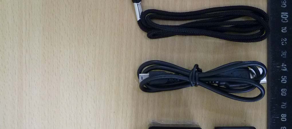
CINDCT-511
Jul 21, 20142.4G Digital Two-Way Tour Guide System
Equipment Class
DTS - Digital Transmission System