CNACT200Wireless Security Monitor Transmitter
Capricorn Electronics Inc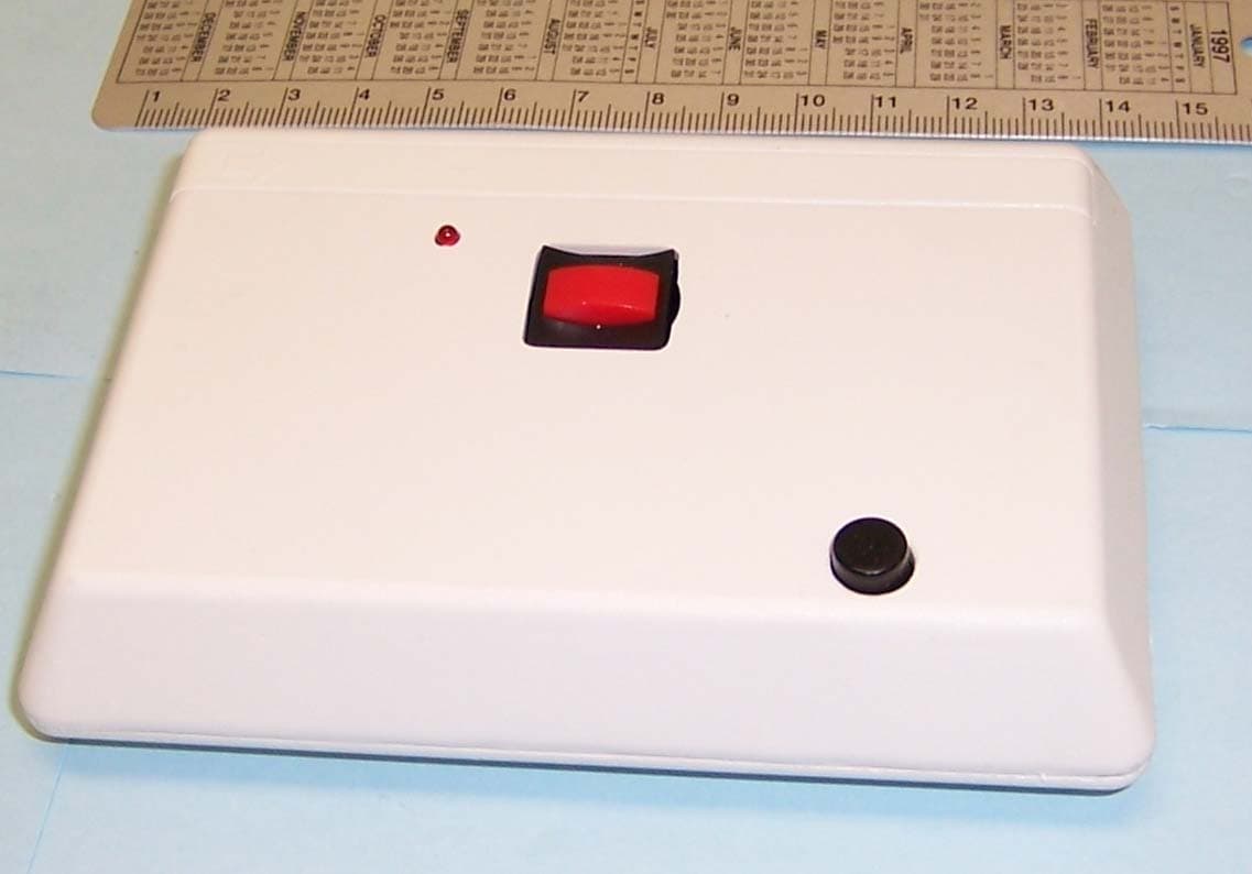
Click to zoom
Application Details
- Equipment Class
- DSC - Part 15 Security/Remote Control Transmitter
- Date of Grant
- Mar 28, 2005
- Application Purpose
- Original Equipment
- Date of Application
- Mar 28, 2005
- Equipment Note
- Wireless Security Monitor Transmitter
- Frequency Range
- 313.50000000 - 313.50000000
- Company
- Capricorn Electronics Inc
- Country
- United States
Documents & Files
Document Text
Text extracted from the exhibit documents filed with the FCC. Open a document above to read the original.
Users Manual
INSTALLATION and USER GUIDE CT-200 TRANSMITTER PLEASE READ THE QUALIFICATION AND WARRANTY STATEMENTS ON THE BACK OF THIS SHEET PRODUCT DESCRIPTION Three CT-200 versions are available for use in retirement communities, assisted living facilities, and full time nursing homes. In most cases, they will be part of a network of transmitters and receivers tied back to a central location (nurse's station, etc.). All versions are powered by long life lithium batteries. CT-200RB Has both emergency and responder switches. CT-200CK Same as "RB" but includes activity monitoring. CT-200SD Use with existing smoke alarm systems to send RF report to nurses' station. RF TESTING The CT-200 must be positioned to provide a strong signal to the system's receiver. Refer to the appropriate receiver installation manual for details on testing the signal. Temporarily place the transmitter at the selected location then activate it by pressing a switch or causing a smoke detector to trip. Do not hold the transmitter in your hand. Use a piece of tape to hold the CT-200 in place if needed. Sometimes a small change in transmitter location or orientation can overcome a marginal signal. Reconfirm signal reception after the transmitter is permanently mounted. INSTALLATION General Guidelines: Do not expose the CT-200 to moisture or to temperatures outside of its operating range (40° to 120° F). Avoid mounting the CT-200 on metal frames or surfaces. You may need to space the housing off at least 1/4" when mounting on metal. CT-200SD The CT-200SD should be mounted within 3" of an existing smoke detector with the microphone opening on the side of the case facing the detector. Modern smoke detectors sound in a cycle of three beeps followed by quiet period. The unit should trip (LED lights) by the end of the second beep in the first round of three beeps. Test that the CT-200 trips properly at 6" prior to installing at the 3" distance. If it does not trip by the end of the second beep, increase the microphone's sensitivity until it trips at 6" (see illustration). Do not increase the sensitivity more than required since false alarms might occur in noisy environments. Mounting: On the front of the case. push the narrow plastic strip in the direction of the arrow and remove it. Loosen and remove the two exposed screws. Lift the front away from the back of the case. CAUTION: Static electricity can damage electronic components. Always touch a grounded, bare metal surface before working with the CT-200. Place the back against the wall and mark the location of the mounting holes. Use an awl or small Philips head screwdriver to make holes for the blue screw anchors. Mount the back with the screws provided. (Note: The holes match up with standard recessed receptacle wall boxes.) Set the transmitter's identification number into the coding switches, install the battery as indicated by the label in the battery well, then reattach the front to the back of the case. OPERATION The LED of the front of the case lights to indicate an RF report whenever the emergency switch (large red button), responder switch (small black button), or smoke detector microphone are activated. The LED continues to blink after the report if the alarm was caused by the emergency switch. It will blink until the responder switch is pressed. While the LED is blinking, the CT-200 will retransmit the alarm signal every 5 minutes until the responder switch is pressed (up to 8 hours). The CT-200CK's includes an activity monitor that requires the resident to press the responder switch within a 3 hour window each day. The LED blinks rapidly to remind the resident during the window. To set the widow start time, press and hold in the responder switch until the LED blinks 4 times. For example, to set a window from 7:30 AM to 10:30 AM. press and hold the responder switch at 7:30 AM. There are no switches on the CT-200SD. CT-200's automatically transmit a status/battery report every 66 minutes. TRANSMITTER CODING Set the ID of the transmitter into the 12 coding switches on the transmitter circuit board. Use a small pointed object such as a paper clip to move the switch. Setting instructions are found in the receiver installation manual. BATTERY The CT-200 uses a single CR123A lithium battery. Battery voltage (good/low) is reported with each hourly check-in report. We recommend that the facility's staff change the batteries on a regular basis for each user. SPECIFICATIONS Size: 4.7" L x 3.3" W x 1.0" H Battery: Single CR123A, 3 volt, lithium battery. Typical Battery Life: Five years for CT-200RB and CT-200SD. Four years for CT-200CK. Operation at the temperature extremes may reduce battery life. Lithium batteries have a recommended shelf life of 10 years. Operating temperature range: 40° to 120° F TESTING No electronic product can perform better than the care and maintenance it receives. Occasionally, residents may be shown how and when to test the CT-200. In most cases, however, testing should be done by the facility's staff. All testing actions must be confirmed at the central monitoring location (nurses' station, etc.). Complete testing of all parts of the system should be performed no less than once per month. In some cases, more frequent tests may be appropriate. Only the on-site facility personnel can make this determination. UNDERSTANDING RADIO FREQUENCY DEVICES Although radio transmission links have proven themselves by providing dependable communication, both customer and installer need to understand their limitations and restrictions before using the system. Refer to each system's receiver Installation Guide for additional RF information. The system's radio reception may be changed when electronic devices, computers, large appliances, mirrors, foil wallpaper, etc., are added or moved within the residence. Have your customer notify you if they have any concerns when making changes of this nature. Some of the areas you should be aware of are: Transmitters have limited power …
Text truncated - open the document above for the full version.
Cover Letter(s)
Letter Of Agency February 11, 2005 American Telecommunications Certification Body, Inc. 6731 Whittier Avenue Suite C110 McLean, VA 22101 To Whom It May Concern: Please be advised that Capricorn Electronics, Inc. authorizes Washington Laboratories, Ltd to act on our behalf, until otherwise notified, for applications to American Telecommunications Certification Body, Inc. We certify that we are not subject to denial of federal benefits, that includes FCC payments, pursuant to Section 5301 of the Anti-Drug Abuse ACT of 1988, U.S.C. 862. Further, no party, as defined in 47 CFR 1.2002(b), to the application is subject to denial of federal benefits, that includes FCC benefits. Thank you for your attention to this matter. William H. Gronning VP of Engineering Capricorn Electronics, Inc.
Cover Letter(s)
Request for Confidentiality February 11, 2005 American Telecommunications Certification Body, Inc. 6731 Whittier Avenue Suite C110 McLean, VA 22101 RE: Certification Application FCC ID: CNACT200 Please be advised that the following exhibits are to be held confidential on behalf of Capricorn Electronics, Inc.: Schematic Block Diagram Operational Description The application contains technical information that Capricorn Electronics, Inc. deems to be trade secrets and proprietary. If made public, the information might be used to the disadvantage of the applicant in the marketplace. Thank you for your attention to this matter. William H. Gronning VP of Engineering Capricorn Electronics, Inc.
External Photos
Top Side Side Side Side Bottom
Internal Photos
Cover Removed PCB Removed From Housing Bottom View of PCB Additional View
Test Report
Document 8560-01, Rev. 0 FCC ID: CNACT200 FCC Certification Test Report Washington Laboratories, Ltd March 2005 FCC Certification Test Report for Capricorn Electronics Inc. FCC ID: CNACT200 March 10, 2005 Prepared for: Capricorn Electronics Inc. 48 Capricorn Drive Maiden, NC 28650 Prepared By: Washington Laboratories, Ltd. 7560 Lindbergh Drive Gaithersburg, Maryland 20879 FCC Certification Test Report Document 8560-01, Rev. 0 FCC ID: CNACT200 FCC Certification Test Report Washington Laboratories, Ltd March 2005 FCC Certification Test Program FCC Certification Test Report for the Capricorn Electronics Inc. CT-200 Transmitter FCC ID: CNACT200 March 10, 2005 WLL JOB# 8560 Prepared by: Brian J. Dettling Documentation Specialist Reviewed by: Gregory M. Snyder Chief EMC Engineer Document 8560-01, Rev. 0 FCC ID: CNACT200 FCC Certification Test Report Washington Laboratories, Ltd March 2005 ii Abstract This report has been prepared on behalf of Capricorn Electronics Inc. to support the attached Application for Equipment Authorization. The test report and application are submitted for a Periodic Intentional Radiator under Part 15.231 of the FCC Rules and Regulations. This Federal Communication Commission (FCC) Certification Test Report documents the test configuration and test results for a Capricorn Electronics Inc. CT-200 Transmitter. Testing was performed on an Open Area Test Site (OATS) of Washington Laboratories, Ltd, 7560 Lindbergh Drive, Gaithersburg, MD 20879. Site description and site attenuation data have been placed on file with the FCC's Sampling and Measurements Branch at the FCC laboratory in Columbia, MD. Washington Laboratories, Ltd. has been accepted by the FCC and approved by NIST NVLAP (NVLAP Lab Code: 200066-0) as an independent FCC test laboratory. The Capricorn Electronics Inc. CT-200 Transmitter complies with the limits for a Periodic Intentional Radiator device under Part 15.231 of the FCC Rules and Regulations. Document 8560-01, Rev. 0 FCC ID: CNACT200 FCC Certification Test Report Washington Laboratories, Ltd March 2005 iii Table of Contents Abstract ............................................................................................................................... ii 1 Introduction..............................................................................................................1 1.1 Compliance Statement .........................................................................................1 1.2 Test Scope ............................................................................................................1 1.3 Contract Information............................................................................................1 1.4 Test Dates ............................................................................................................1 1.5 Test and Support Personnel .................................................................................1 2 Equipment Under Test .............................................................................................2 2.1 EUT Identification & Description .......................................................................2 2.2 Test Configuration ...............................................................................................2 2.3 Testing Algorithm................................................................................................2 2.4 Test Location .......................................................................................................2 2.5 Measurements ......................................................................................................3 2.5.1 References........................................................................................................3 2.6 Measurement Uncertainty....................................................................................3 3 Test Equipment ........................................................................................................4 4 Test Results ..............................................................................................................5 4.1 Duty Cycle Calculation and Transmitter Timing (§15.35 and §15.231(a)).........5 4.2 Occupied Bandwidth: (FCC Part §2.1049 and §15.231) .....................................8 4.3 Radiated Spurious Emissions: (FCC Part §2.1053 and 15.231(b)) .....................9 4.3.1 Test Procedure...............................................................................................9 List of Tables Table 1. Device Summary.................................................................................................. 2 Table 2: Test Equipment List............................................................................................. 4 Table 3. Duty Cycle Correction ......................................................................................... 7 Table 4. Occupied Bandwidth Results............................................................................... 8 Table 6. Radiated Emissions Test Data, Unit Upright..................................................... 10 Table 7: Radiated Emission Test Data, Unit Sideways ................................................... 11 Table 8: Radiated Emission Test Data, Unit Flat ............................................................ 12 List of Figures Figure 1. Duty Cycle Plot, Worst Case 100ms ................................................................... 6 Figure 2. Duty Cycle Plot, Pulse Width and Count ............................................................ 7 Figure 3. Occupied Bandwidth ........................................................................................... 8 Document 8560-01, Rev. 0 FCC ID: CNACT200 FCC Certification Test Report Washington Laboratories, Ltd March 2005 Page 1 of 12 1 Introduction 1.1 Compliance Statement The Capricorn Electronics Inc. CT-200 Transmitter complies with the limits for a Periodic Intentional…
Text truncated - open the document above for the full version.
Test Setup Photos
Upright Side Flat
Contact Information
Applicant
William H Gronning(Engineering V.P.)
Technical Contact
Washington Laboratories, Ltd.Gregory M Snyder
[email protected]301 417 0220
7560 Lindbergh Drive · Gaithersburg, Maryland · United States
Test Firm
Windermere Information Technology SystemsWilliam Banchero
Technical Specifications
| # | Rule Parts | Frequency Range | Power Output |
|---|---|---|---|
| 1 | 15.231 | 313.5 MHz - 313.5 MHz | - |
Other Applications from Capricorn Electronics Inc
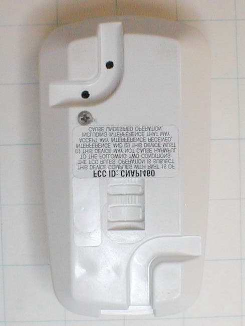
CNAPI460
Oct 16, 2002Security/Remote Transmitter
Equipment Class
DSC - Part 15 Security/Remote Control Transmitter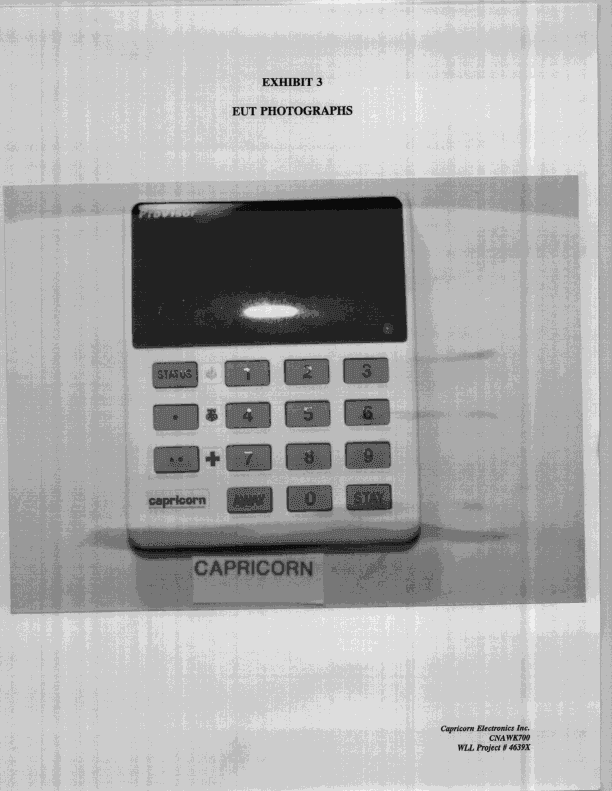
CNAWK700
Oct 28, 1998Keypad Transmitter
Equipment Class
DSC - Part 15 Security/Remote Control TransmitterCNAPE600
Nov 21, 1996Pendant Transmitter
Equipment Class
DSC - Part 15 Security/Remote Control TransmitterCNA300PERS
Oct 10, 1995Personal Emergency Response System Receiver
Equipment Class
CRR - Superregenerative ReceiverCNAFX-1000
Feb 28, 1993Security System Receiver
Equipment Class
CRR - Superregenerative Receiver