Text extracted from the exhibit documents filed with the FCC. Open a document above to read the original.
F-2 2.4GHz system INSTRUCTION MANUAL Thank you for purchasing a F-2 2.4GHz system. Before using your F-2 2.4GHz system, read this manual carefully and use your R/C set safely. After reading this manual, store it in a safe place. 1. Safty guides z Do not cover/hold the built-in antenna part of F-2 transmitter by your hand during running. z Do not perform the linking procedure while motor's main wire is connected or the engine is operating as it may result in serious injury. z When using a Ni-Cd/Ni-MH battery to power your system, always charge and check the battery voltage prior to operation. A. Turning on the power switches Always check the throttle trigger on the transmitter to be sure it is at the neutral position. z Turn on the transmitter power switch. z Turn on the receiver or speed control power switch. B. Turning off the power switches Always be sure the engine is not running or the motor is stopped. z Turn off the receiver or speed control power switch. z Then turn off the transmitter power switch. If the power switches are turned off in the opposite order the model may unexpectedly run out of control and cause a very dangerous situation. 2. Before Operation z Transmitter As with all radio frequency transmissions, the strongest area of signal transmission is from the sides of the antenna(built-in). As such, the antenna(arrow direction) should not be pointed directly at the model. Do not cover/hold the built-in antenna part of F-2 transmitter by your hand during running. Do not put any conductive plate/sticker on the antenna part. Otherwise, the operating range may become shorter. z Receiver 3. Assembly / Adjustment ΒΎ Battery Replacement Method (4 AA size batteries) z Remove the battery cover from the transmitter by sliding it in the direction of the arrow in the figure. z Remove the used batteries. z Load the new AA size batteries.Pay very close attention to the polarity markings and reinser taccordingly. z Slide the battery cover back onto the case. CAUTION Always be sure you reinsert the batteries in the correct polarity order.If the batteries are loaded incorrectly,the transmitter may be damaged. When the transmitter will not be used for any short or long period of time,always remove the batteries.If the batteries do happen to leak, clean the battery case and contacts thoroughly.Make sure the contacts are free of corrosion. Check: Turn the power switch on the transmitter to the ON position. Check the battery voltage display on the LED light. If the voltage is low, check the batteries for insufficient contact in the case or incorrect battery polarity. Low Battery : When the LED starts blinking, change the batteries immediately. The low battery alarm is meant to be a safety feature only. Do NOT operate your radio below low battery. Always shut your radio off as soon as possible after the low battery warning loss of control. ΒΎ Receiver and Servo Connection ΒΎ Receiver Antenna Installation z Install the antenna in the higher place as shown in the figure. z Keep the antenna as far away from the motor, ESC and other noise sources as possible. z Put the antenna in the antenna tube to protect it. z Do not cut the antenna. z Do not bend the coaxial cable. Doing so causes damage. ΒΎ Transmitter/Receiver Binding z Insert the Binding line to the BIND port of the receiver. z Power on the receiver and the LED blinks quickly .This means the receiver are going to binding mode. z Press and hold the BIND button of the transmitter, then power on the transmitter. The bind LED of transmitter flickers and this means the transmitter are going into binding mode. z Transmitter and receiver begin to bind. After binding is completed, the LED of transmitter and receiver will change to solid GREEN. Otherwise, please repeat the above operation again. 4. F-2 Functions A. Steering Trim z Racers Tip When you install a servo, always check to be sure the servo is at its neutral position. Adjust the Steering neutral adjustments can be made bymoving the Steering trim knob to the left or right. servo horn hole position and linkage so both are parallel. When a servo saver is used, place it as close to center position as possible. Be sure the steering trim on the transmitter is at the neutral position. z Trim Operation And Maximum Travel Changing the trim can affect the overall settings. When adjustments are made with the trims, recheck your installation for maximum travel. (Steering D/R). z When Trim usage is extreme If it takes most of your trim movement to get a servo to the neutral position, reposition the servo horn or servo saver on the servo and inspect your linkage installation. B. Throttle Trim Throttle neutral adjustments can be made moving the throttle trim to the left or right. z Racers Tip When using an electronic speed control, set the throttle trim to neutral and make adjustments to the speed control. On a gas powered model, set the trim to neutral and adjust the linkage to the point where the carburetor is fully closed in accordance with the engine instruction manual. z Trim Operation and Travel Trim adjustments will affect the overall servotravel.Check the brake side (backward) movement when changes are made. z When trim movement is extreme If you use most of the trim movement to get the servo to the neutral position ,recenter the servo horn closer to the neutral position and inspect your throttle linkage. C. Steering Dual Rates Use this function to adjust the steering travel of your model. If the model u When the model oversteers, take away steering by turning CCW of the D/R button. Be sure that the steering linkage does not bind or come in contact with any suspension parts or arms. If unreasonable force is applied to the servo, the servo may be damaged and result in loss of control. D. Steering Servo Reversing This function reverses the rotation direction of the Steering servo. When the trim position deviates from the center, the deviation will be on the opposite side when the servo is reversed. E. β¦
Text truncated - open the document above for the full version.
2.4 GHz Ant. 2404~2470MHz Control signal FSK Modulate Crystal Oscillate (16MHz) Frequency Amplifier 2.4GHz Filter Power Output
Fashion Star Technology Limited Model: F-2 REPORT NO.: STR12088079I FCC PART 15.249 EXHIBIT 2 - EUT EXTERNAL PHOTOGRAPHS EUT View 1 EUT View 2 Fashion Star Technology Limited Model: F-2 REPORT NO.: STR12088079I FCC PART 15.249 EUT View 3 EUT View 4 Fashion Star Technology Limited Model: F-2 REPORT NO.: STR12088079I FCC PART 15.249 EUT View 5 EUT View 6 Fashion Star Technology Limited Model: F-2 REPORT NO.: STR12088079I FCC PART 15.249 Adding Mode (F-2A) Adding Mode (F-2A) Fashion Star Technology Limited Model: F-2 REPORT NO.: STR12088079I FCC PART 15.249 Adding Mode (F-2B) Adding Mode (F-2B) Fashion Star Technology Limited Model: F-2 REPORT NO.: STR12088079I FCC PART 15.249 Adding Mode (F-3) Adding Mode (F-3) Fashion Star Technology Limited Model: F-2 REPORT NO.: STR12088079I FCC PART 15.249 Adding Mode (FT-2) Adding Mode (FT-2) Fashion Star Technology Limited Model: F-2 REPORT NO.: STR12088079I FCC PART 15.249 Adding Mode (FT-3) Adding Mode (FT-3) Fashion Star Technology Limited Model: F-2 REPORT NO.: STR12088079I FCC PART 15.249 Adding Mode (BT-T2A) Adding Mode (BT-T2A) Fashion Star Technology Limited Model: F-2 REPORT NO.: STR12088079I FCC PART 15.249 Adding Mode (BT-T2B) Adding Mode (BT-T2B)
Fashion Star Technology Limited Model: F-2 REPORT NO.: STR12088079I FCC PART 15.249 EXHIBIT 1- PRODUCT LABELING Proposed FCC ID Label Format FCC ID: COAF-23AB This device complies with Part 15 of the FCC Rules. Operation is subject to the following two conditions: (1) This device may not cause harmful interference, and (2) this device must accept any interference received, including interference that may cause undesired operation. Specifications : Text is Black in color and justified. Labels are printed in indelible ink on permanent adhesive silk-screened onto the EUT or shall be affixed at a conspicuous location on the EUT. Proposed Label Location on EUT FCC ID Label Location
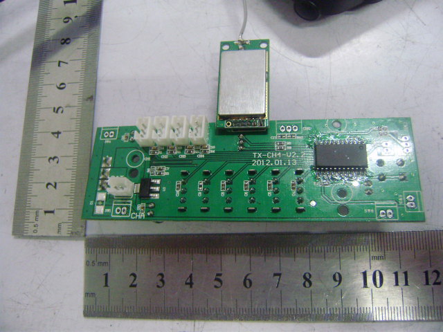
Fashion Star Technology Limited Model: F-2 REPORT NO.: STR12088079I FCC PART 15.249 EXHIBIT 3 - EUT INTERNAL PHOTOGRAPHS EUT Housing and Board View Solder Board-Component View 1 Fashion Star Technology Limited Model: F-2 REPORT NO.: STR12088079I FCC PART 15.249 Solder Board-Component View 2 Solder Board-Component View 3 Fashion Star Technology Limited Model: F-2 REPORT NO.: STR12088079I FCC PART 15.249 Solder Board-Component View 4 Solder Board-Component View 5
CIRCUIT DESCRIPTION Tx Unit: The control signal of button triggered the MCU-P234CS24 which gets a pulse modulation then passing through the MCU, working with 16MHz crystal for producing a signal to the RF module circuit carrying wave amplified by the amplifier circuit unit, through the antenna then transmit out as 2404~2470MHz 1. Functional control board kit deals with the functional controlling. 2. MCU is the main functional control center, deal with function control and other atate indication. 3. Tine frequency is a multiplied frequency to produce an extract HF signal. 4. RF module is used for producing FSK/GFSK modulation.
ABCD DCBA Title Number Revision Size A4 Date: 30-Jul-2012 Sheet of File: E:\ ζͺζ§ \PCB\TX-CH2.DDB Drawn By: 12 J1 SW1 + C11 220UF/16V C5104 OUT IN GND U21117-3.3V + C3 220UF/16V C10104 VCC PC0/CIN3 3 PB0/AD0/INT1/CO 4 PB1/AD1/Vref 5 PB2/AD2 6 GND 7 PB3/AD3 8 PB4/AD4 9 PB5/AD5 10 PB6/AD6 11 PB7/AD7 12 PA0/INT0/COM0 13 PA5/RESET# 14 PA1/PWM/COM1 15 PA2/PWM/COM2 16 PA3/AD8/PWM/COM3/CIN1- 17 VDD 18 PA6/X2 19 PA7/X1 20 PA4/AD9/CIN2- 21 PC5/CIN+ 22 PC1 2 PC2 1 PC4 23 PC3 24 U1 P234CS24 B1 BIND D2 BIND LED D3 POWER LED R9 471 R8 471 VCCVCC SW2ST_REVSW3TH_REV 12345 J2 SCSSCK SDIO VCC SCSSCK SDIO VR4TH_High R7 100 C1104 VCC VR5TH_Low R11 100 C8104 VCC VR1TH_TRIM R10 100 C9104 VCC VR3ST_D/R R3 100 C12104 VCC VR2ST_TRIM R4 100 C4104 VCC R61.8KR51K POW POW 123 CH2 VCC C13103 R2100 123 CH1 VCC C6103 R1100 VCC + C2 220UF/16V C7104 F-2 2012.07.30 1 2 3 4 56 ABCD 6 5 4 3 2 1 D CBA Title Number Revision Size B Date: 7-Mar-2012 Sheet of File: E:\FRC\PCB\MD7105-AP1110.DDB Drawn By: FR8008 C42 15pF PA_IN C571uF C71uF VIN33 VIN33 VIN33 C101.2pF R13510 L12.7nH C8NC C13 0.1uF R3 750 R4300 C26120pF C331.2pF C27 NC VCC 1 RFIN 2 VCC_Bias 3 NC 4 VB1 5 VB2 6 RFOUT 7 RFOUT 8 U3AP1110 L32.0nH C251.2pF R8 1.1k vb1vb2 vb1vb2 L2 2.7nH C30560pF R10200 C3110nF C3233pF Y116MHz SCSSCKSDIO C2 120pF C3433pF VDD_D C172.2uF L91.2nH C22 10pF CKO GIO2 GIO1 VIN33 REGOA C5100pF C3 1.5nF C14 100pF C23 0.1uF C240.1uF VDA2 C290.1uF C15100pF REGOA REGOA RSSI BPBG C162.2uF R110 VDPLL RSSI 1 BPBG 2 RFI 3 RFO 4 VDA2 5 VT 6 GND 7 XI 8 XO 9 VDA3 10 SCS 11 SCK 12 DVDD 13 SDIO 14 GND 15 CKO 18 GIO2 17 GIO1 16 REGI 19 VDA1 20 A7105PKG U1 A7105PKG L83.1nH C182.2uF C21 1pF C20 1pF SCSSCKSDIOGNDVIN33 R29K PA_IN 12345 J2CON5 TP1TP GND 1 GND 2 GND 3 OUT 4 GND 5 GND 6 GND 7 IN 8 LF1LF2012 V2.0
Fashion Star Technology Limited Model: F-2 FCC Part 15C Measurement and Test Report For Fashion Star Technology Limited A-2305, Cyber Times, Tianβan Cyber Park Futian District, Shenzhen, China FCC ID: COAF-23AB FCC Rules: FCC Part 15.249 Product Description: 2.4G Radio Control System Tested Model: F-2 Report No.: STR12088079I Tested Date: 2012-08-10 to 2012-08-24 Issued Date: 2012-09-03 Tested By: Susan Su / Engineer Reviewed By: Lahm Peng / EMC Manager Approved & Authorized By: Jandy so / PSQ Manager Prepared By: SEM.Test Compliance Service Co., Ltd 3/F, Jinbao Commerce Building, Xin'an Fanshen Road, Bao'an District, Shenzhen, P.R.C.οΌ518101οΌ Tel.: +86-755-33663308 Fax.: +86-755-33663309 Website: www.semtest.com.cn Note: This test report is limited to the above client company and the product model only. It may not be duplicated without prior permitted by SEM.Test Compliance Service Co., Ltd REPORT NO.: STR12088079I PAGE 1 OF 23 FCC PART 15.249 Fashion Star Technology Limited Model: F-2 TABLE OF CONTENTS 1. GENERAL INFORMATION ...................................................................................................................................3 1.1 PRODUCT DESCRIPTION FOR EQUIPMENT UNDER TEST (EUT)...............................................................................3 1.2 TEST STANDARDS...................................................................................................................................................4 1.3 TEST METHODOLOGY.............................................................................................................................................4 1.4 TEST FACILITY.......................................................................................................................................................4 1.5 EUT SETUP AND TEST MODE.................................................................................................................................5 2. SUMMARY OF TEST RESULTS ...........................................................................................................................6 3. ANTENNA REQUIREMENTS................................................................................................................................7 3.1 STANDARD APPLICABLE.........................................................................................................................................7 3.2 TEST RESULT..........................................................................................................................................................7 4. RADIATED EMISSIONS .........................................................................................................................................8 4.1 MEASUREMENT UNCERTAINTY..............................................................................................................................8 4.2 STANDARD APPLICABLE.........................................................................................................................................8 4.3 TEST EQUIPMENT LIST AND DETAILS.....................................................................................................................8 4.4 TEST PROCEDURE...................................................................................................................................................9 4.5 CORRECTED AMPLITUDE & MARGIN CALCULATION..............................................................................................9 4.6 ENVIRONMENTAL CONDITIONS..............................................................................................................................9 4.7 SUMMARY OF TEST RESULTS/PLOTS....................................................................................................................10 5. OUT OF BAND EMISSIONS.................................................................................................................................18 5.1 STANDARD APPLICABLE.......................................................................................................................................18 5.2 TEST EQUIPMENT LIST AND DETAILS...................................................................................................................18 5.3 TEST PROCEDURE.................................................................................................................................................18 5.4 ENVIRONMENTAL CONDITIONS............................................................................................................................18 5.5 SUMMARY OF TEST RESULTS/PLOTS....................................................................................................................18 6. EMISSION BANDWIDTH .....................................................................................................................................21 6.1 STANDARD APPLICABLE.......................................................................................................................................21 6.2 TEST EQUIPMENT LIST AND DETAILS...................................................................................................................21 6.3 TEST PROCEDURE.................................................................................................................................................21 6.4 ENVIRONMENTAL CONDITIONS............................................................................................................................21 6.5 SUMMARY OF TEST RESULTS/PLOTS....................................................................................................................21 REPORT NO.: STR12088079I PAGE 2 OF 23 FCC PART 15.249 Fashion Star Technology Limited Model: F-2 1. GENERAL INFORMATION 1.1 Product Description for Equipment Under Test (EUT) Client Information Applicant: Fashion Star Technology Limited Address of applicant: β¦
Text truncated - open the document above for the full version.
Fashion Star Technology Limited Model: F-2 REPORT NO.: STR12088079I FCC PART 15.249 EXHIBIT 4 - TEST SETUP PHOTOGRAPHS Radiation Emission Test Setup (Below 30MHz) Radiation Emission Test Setup (30MHz to 1GHz) Fashion Star Technology Limited Model: F-2 REPORT NO.: STR12088079I FCC PART 15.249 Radiation Emission Test Setup (Above 1GHz)
| # | Rule Parts | Frequency Range | Power Output |
|---|---|---|---|
| 1 | 15C | 2.40 GHz - 2.47 GHz | - |

2.4G MINI RADIO CONTROL SYSTEM
Equipment Class
DXX - Part 15 Low Power Communication Device Transmitter