FCCID.CO- FCC ID Database
HomeCompaniesEquipment ClassesSearch

© 2026 FCC ID Database. All rights reserved.

AboutContactData sourced from FCC public records
  1. Home/
  2. CORE OPTIX Inc./
  3. CR4-TZC-BH02

CR4-TZC-BH02Smart-Stand

CORE OPTIX Inc.
Smart-Stand - FCC ID CR4-TZC-BH02 - CORE OPTIX Inc.
Click to zoom

Application Details

Equipment Class
DSS - Part 15 Spread Spectrum Transmitter
Date of Grant
Jul 11, 2012
Application Purpose
Original Equipment
Date of Application
Jul 11, 2012
Equipment Note
Smart-Stand
Frequency Range
2402.00000000 - 2480.00000000
Company
CORE OPTIX Inc.
Country
South Korea

Documents & Files

Select a file to view
Users Manual

↗

Cover Letter(s)

↗
↗

External Photos

↗

ID Label/Location Info

Internal Photos

↗

Test Report

↗

Test Setup Photos

↗

Document Text

Text extracted from the exhibit documents filed with the FCC. Open a document above to read the original.

Users Manual

Before use Handset (TZC-BH02)Aluminium charging standUser manual Overview Charging handset When TZC-BH01 mono handset is used first time after purchase, blue and red LED’s blink and it gets into standby (pairing) mode if power is on. Connecting (pairing) handsetTurning on/off handset Active substance œ Register hands-free(HFP) mode or headset(HSP) mode in case of registering TZC-BH01 from mobile phone. But, menu composition may be different along the mobile phone. Refer to the user’s manual of the mobile phone. On How to use Tone Indicator Off Press power/talk button for more than 3 seconds. Power is on with beep sound Blue and red LED’s are turned on at a time and each LED indicates the status. Power is off with beep sound. Blue and red LED’s are turned on at a time and turned off.  If it is registered to the mobile phone, it is connected to the first automatically-registered mobile phone when turns off and on the handset. Registering it again after first registration If presses power/talk button for more than 3 seconds while the power of handset is off, beep sound remits and blue and red LED’s are turned on and power is turned on. At this condition, if the hand is not released from the button for 1~2 seconds (pressing time while power is on) continuously, beep sound emits and blue and red LED’s blink fast and it gets into standby mode (pairing). Hereafter, proceed with the registration from No. 2) connecting handset. Registering other mobile phone œ If Smart-stand is not searched during above No. 2) Bluetooth device search, turn off and on the handset and mobile phone and try the registration again.. œ If it is not connected, check if the Bluetooth function of the mobile phone is activated or not. If completes the registration, beep sound emits every 5 seconds and blue LED blinks twice.  Search Bluetooth device from Bluetooth setting menu of the mobile phone.  Select Smart-Stand out of the devices in the mobile phone. œ Please check the compatibility of your products before use because there may be some cases they do not support the phone function according to the policies of products or service operators.   œ If it passes 5 minutes with disconnected condition, the power of handset is turned off automatically. If the handset gets out of wireless coverage (within 10m) of mobile phone, the connection with the mobile phone is cancelled and the handset gets connected with the mobile phone and if handset gets close to mobile phone within wireless coverage again, the handset is connected with mobile phone automati-cally. Automatic connection If requires password in the process of registration, input 0000.  TZC-BH01 Bluetooth handset is pen-type mono handset which applies Bluetooth technology. You can use the functions such as phone, internet phone and others the devices provide with by connecting this product freely with all mobile phones, smart phones, smart pads, notebook computers and desktop computers which support the Bluetooth profiles of headset (HSP) and hands-free (HFP). Receiver Volumeup/down Search Smart-Stand œ Screen display or connecting method may be different along the mobile phone. Refer to the user’s manual of the mobile phone. Phone-type Bluetooth Mono Handset TZC-BH02 User Manual www.tanzency.com Smart-Stand FCC STATEMENTThis device complies with part 15 of the FCC Rules. Operation is subject to the following two conditions:1. This device may not cause harmful interference, and2. This device must accept any interference received , including interference that may cause undesiredoperation.[Note] The manufacturer is not responsible for AzNY interference, for example RADIO or TV interference,caused by unauthorized modifications to this equipment. Such modifications could void the user’sauthority to operate the equipment. EUThis product is CE marked according to the provision of the R&TTE Directive (99/5/EC).Here by CoreOptix Inc. declares that this product is in compliance with the essential requirements and other relevant provisions of Directive 1999/5/EC. Bluetooth enables you to use the mobile phone, portable device, peripheral device and others freely within the wireless range of 10m connecting it with them as the wireless technol-ogy for short distance. œ The coverage may be shortened a bit near the obstacle with the strong radio interference and the devices with the same frequency range. œ੹౵ߑ೧о ߂ޛݒ੢ъೠ زੌ઱౵ࣻ؀੄ ӝӝ઱߸ীࢲח ࣗ׮оܻਊѢࢎ ૣই૕ࣻ੓ ׮פण ܖ࠶ైझח ӔѢܻীࢲ ോ؀੹ച  ോ؀ਊ݈ױ ӝ  ઱߸੢஖ ١ਸޖࢶਵ۽োѾೞחӝࣿ಴ળӏѺਵ۽N੉ղীࢲ੗ਬ܂ѱোѾೞৈࢎਊೡࣻ੓ण׮פ 10m œ The size adjuster can put reversely to adjust the length according to the Mobile size. Carefully reinsert the size adjuster not to be breakage. 4J[FBEKVTUFS 4NBSUQIPOF DSBEMF $IBSHJOH QJO 64#DBCMF power /talk button mic LED Reset hole $IBSHJOHQMBUF The Handset has battery inside. Recommend to fully charge the Handset battery before first using. If the handset place on the stand of Aluminum, it recharges automatically. The handset should be located on in the middle of stand. If the charging starts, the Red Led light under handset will be reflected on the upper side of Aluminum. (If run out of battery, please recharge the handset fully before using.)You can use the function of handset during charging. Battery charging time is about within 3 hours. (If the charging starts, blue LED light is on.)  Do not charge the headset with the charger other than the approved one. It may cause the breakdown or damage. In case battery power is insufficient, warning sound emits every 5 seconds and red LED blinks twice. Caution : Low battery :  œ In case of some of mobile phones, the call log is displayed in the window and the call is connected with the recently-used phone number if presses power/talk button twice shortly in succession. Model nameVersionFrequencyScopeTransmissionOutputBluetoothProfile Smart-Stand / TZC-BH02 Handset(Radio data communication system)Bluetooth Ver. 3.0Headset profile (HSP) / Hands-free profile (HFP)2.402 ~…

Text truncated - open the document above for the full version.

External Photos

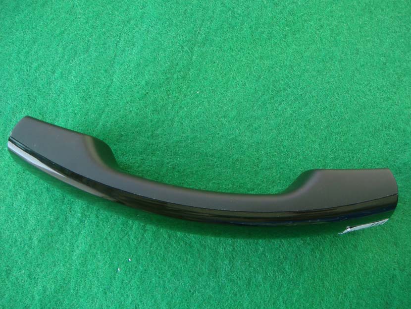
SK TECH CO., LTD. Page 1 of 4 SKTRFC-120709-015 FCC ID: CR4-TZC-BH02 External Photographs of EUT <Photograph 1: Front View> <Photograph 2: Rear View> SK TECH CO., LTD. Page 2 of 4 SKTRFC-120709-015 FCC ID: CR4-TZC-BH02 <Photograph 3: Left-side View> <Photograph 4: Right-side View> SK TECH CO., LTD. Page 3 of 4 SKTRFC-120709-015 FCC ID: CR4-TZC-BH02 <Photograph 5: Battery charger – Front view> <Photograph 6: Battery charger – Rear view> SK TECH CO., LTD. Page 4 of 4 SKTRFC-120709-015 FCC ID: CR4-TZC-BH02 <Photograph 6: Battery charging point>

Internal Photos

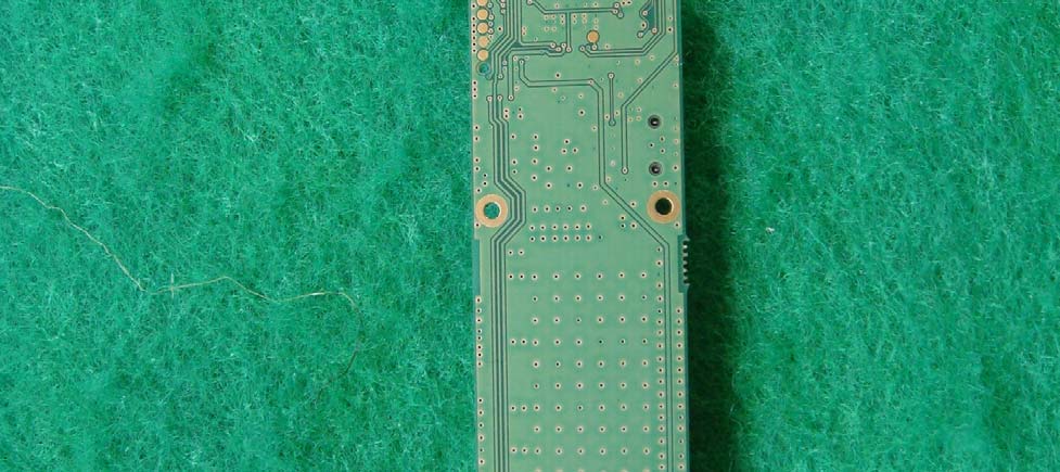
SK TECH CO., LTD. Page 1 of 7 SKTRFC-120709-015 FCC ID: CR4-TZC-BH02 Internal Photographs <Photograph 1: Cover removed> SK TECH CO., LTD. Page 2 of 7 SKTRFC-120709-015 FCC ID: CR4-TZC-BH02 <Photograph 2: Main board- Front view> SK TECH CO., LTD. Page 3 of 7 SKTRFC-120709-015 FCC ID: CR4-TZC-BH02 <Photograph 3: Main board- Rear view> SK TECH CO., LTD. Page 4 of 7 SKTRFC-120709-015 FCC ID: CR4-TZC-BH02 <Photograph 4: RF Zoom in> SK TECH CO., LTD. Page 5 of 7 SKTRFC-120709-015 FCC ID: CR4-TZC-BH02 <Photograph 5: Battery> SK TECH CO., LTD. Page 6 of 7 SKTRFC-120709-015 FCC ID: CR4-TZC-BH02 <Photograph 6: Battery Charger Housing removed > SK TECH CO., LTD. Page 7 of 7 SKTRFC-120709-015 FCC ID: CR4-TZC-BH02 <Photograph 7: Battery> <Photograph 8: Battery>

Test Report

SK TECH CO., LTD. Page 2 of 31 SKTRFC-120709-015 FCC ID: CR4-TZC-BH02 >> CONTENTS << 1. GENERAL ···························································································4 2. TEST SITE ···························································································4 2.1 Location ·························································································4 2.2 List of Test and Measurement Instruments ·················································5 2.3 Test Date ·························································································5 2.4 Test Environment ···············································································5 3. DESCRIPTION OF THE EQUIPMENT UNDER TEST ··································6 3.1 Rating and Physical Characteristics ·························································6 3.2 Equipment Modifications ·····································································6 3.3 Submitted Documents ·········································································6 4. MEASUREMENT CONDITIONS ······························································7 4.1 Description of test configuration ·····························································7 4.2 List of Peripherals ··············································································7 4.3 Type of Used Cables ···········································································7 4.4 Uncertainty ······················································································7 5. TEST AND MEASUREMENTS ·································································8 5.1 ANTENNA REQUIREMENT ······························································8 5.1.1 Regulation ··················································································8 5.1.2 Result ·······················································································8 5.2 MAXIMUM PEAK OUTPUT POWER ·················································9 5.2.1 Regulation ··················································································9 5.2.2 Test Procedure ·············································································9 5.2.3 Test Results ················································································9 Table 1: Measured values of the Maximum Peak Output Power (Conducted)····························9 Figure 1: Plot of the Maximum Peak Output Power (Conducted) ········································· 10 5.3 CARRIER FREQUENCY SEPARATIONS and 20 dB BANDWIDTH ·········· 11 5.3.1 Regulation ················································································ 11 5.3.2 Test Procedure ··········································································· 11 5.3.3 Test Results ·············································································· 11 Table 2: Measured values of the Carrier Frequency Separation and 20 dB Bandwidth ·············· 11 Figure 2: Plot of the Carrier Frequency Separation ························································ 12 Figure 3: Plot of the 20dB Channel Bandwidth ····························································· 13 5.4 NUMBER OF HOPPING CHANNELS ················································ 14 5.4.1 Regulation ················································································ 14 5.4.2 Test Procedure ··········································································· 14 5.4.3 Test Results ·············································································· 14 Table 3: Measured values of the Number of Hopping Channels ········································ 14 Figure 4: Plot of the Number of Hopping Channels ························································ 15 SK TECH CO., LTD. Page 3 of 31 SKTRFC-120709-015 FCC ID: CR4-TZC-BH02 5.5 TIME OF OCCUPANCY (DWELL TIME) ··········································· 16 5.5.1 Regulation ················································································ 16 5.5.2 Test Procedure ··········································································· 16 5.5.3 Test Results ·············································································· 16 Table 4: Measured values of the Time of Occupancy ····················································· 16 Figure 5: Plot of the Time of Occupancy ···································································· 17 5.6 SPURIOUS EMISSION, BAND EDGE, AND RESTRICTED BANDS ········· 18 5.6.1 Regulation ················································································ 18 5.6.2 Test Procedure ··········································································· 18 5.6.3 Test Results ·············································································· 20 Table 5: Results for the final radiated measurements of the field strength of spurious emission····· 20 Figure 6: Plot of the Band Edge (Conducted) ································································ 21 Figure 7: Plot of the Band Edge (Radiated) ··································································· 22 Figure 8: Spurious RF conducted emission ··································································· 24 Figure 9: Emission plot for the preliminary radiated measurements ······································ 25 5.7 AC POWER LINE CONDUCTED EMISSIONS ···································· 28 5.7.1 Regulation ················································································ 28 5.7.2 Test Procedure ··········································································· 28 5.7.3 Test Results ·············································································· 29 Table 6: Measured values of the Conducted Emissions ···················································· 29 Figure 10: Plot of the Conducted Emissions ·········································…

Text truncated - open the document above for the full version.

Test Setup Photos

SK TECH CO., LTD. Page 1 of 3 SKTRFC-120709-015 FCC ID: CR4-TZC-BH02 Test set up photos <Radiated Emissions - Front View> <Radiated Emissions - Rear View> SK TECH CO., LTD. Page 2 of 3 SKTRFC-120709-015 FCC ID: CR4-TZC-BH02 <Radiated Emissions - below 30 MHz> <Radiated Emissions - below 1 GHz> SK TECH CO., LTD. Page 3 of 3 SKTRFC-120709-015 FCC ID: CR4-TZC-BH02 <Radiated Emissions - above 1 GHz> <AC Power Line Conducted Emissions>

Contact Information

Applicant

Yunjung CHUNG
[email protected]+82415442181Fax: +82415442182

Test Firm

SK Tech Co., LTD.Yoon Jongsoo
[email protected]82-31-576-2204Fax: 82-31-576-2205

Technical Specifications

#Rule PartsFrequency RangePower Output
115C2.40 GHz - 2.48 GHz330.00 µW
Confidentiality
Long Term
Grant Notes
Power output listed is peak conducted. This device and its antenna(s) must not be co-located or operating in conjunction with any other antenna or transmitter except in accordance with FCC accepted multi-transmitter procedures.

Other Applications from CORE OPTIX Inc.

Blue-fin - FCC ID CR4-TZC-BH01 - CORE OPTIX Inc.
CR4-TZC-BH01

Blue-fin

Mar 20, 2012

Equipment Class

DSS - Part 15 Spread Spectrum Transmitter