CVO50001computer assisted stereotaxic surgical instrument system
Orthosoft Inc.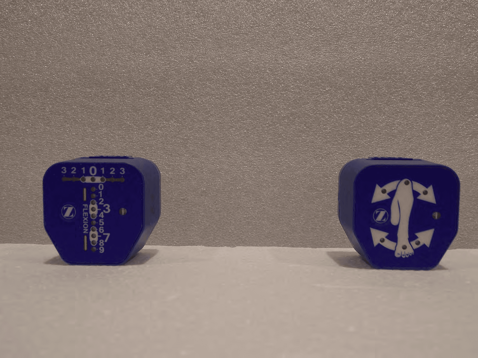
Click to zoom
Application Details
- Equipment Class
- DTS - Digital Transmission System
- Date of Grant
- Mar 10, 2021
- Application Purpose
- Original Equipment
- Date of Application
- Mar 09, 2021
- Equipment Note
- computer assisted stereotaxic surgical instrument system
- Frequency Range
- 2405.00000000 - 2480.00000000
- Company
- Orthosoft Inc.
- Country
- Canada
Documents & Files
Document Text
Text extracted from the exhibit documents filed with the FCC. Open a document above to read the original.
Users Manual
iASSIST ® Knee 2-Pod Version Surgical Technique Table of Contents Overview ..............................................................................................................................................2 Indication for Use .....................................................................................................................2 Training .........................................................................................................................................2 Implant Indications ..................................................................................................................2 Contraindications .....................................................................................................................2 Complications ............................................................................................................................2 Target Population and Clinical Peformance ....................................................................2 Reporting Problems .................................................................................................................2 Preoperative Guide ...........................................................................................................................3 iASSIST V2 Tablet Setup ..........................................................................................................3 Application Launch and Patient Side Selection ............................................................5 Buttons, Icon and Pod Status Bar ........................................................................................6 Intraoperative Guide ........................................................................................................................8 Instrument Assembly ..............................................................................................................8 Powering On the Pods and Intraoperative Calibration .............................................10 Pod Assembly ..........................................................................................................................12 Femur Procedure ....................................................................................................................13 Tibia Procedure .......................................................................................................................22 Alternate Techniques to Prepare Tibia Cut ....................................................................34 Surgical Technique for Bilateral Procedure ...................................................................43 Surgical Transition (Stop Button) ......................................................................................44 Pod Replacement (Sterility Compromised - Faulty Pod) ..........................................44 Postoperative Guide .......................................................................................................................45 Connection to the Internet .................................................................................................45 Case Date Manager ................................................................................................................46 Updating the System .............................................................................................................48 Date, Time and Regulatory Region ..................................................................................50 Shutdown the iASSIST V2 Tablet .......................................................................................50 Equipment Inventory and Cleaning/Sterilization Methods .............................................51 Sterilization Parameters........................................................................................................52 iASSIST Knee Master Instrument Kit ................................................................................53 Disposables ...............................................................................................................................59 iASSIST V2 Tablet Kit ..............................................................................................................60 General Equipment Information .......................................................................................60 Product Specifications and Regulatory Notices ..........................................................65 Symbols and Icons .................................................................................................................74 For iAssist Knee error information, please reference the iAssist Knee Error Guide. 2 | iASSIST 2-Pod Version Surgical Technique 1.1 Indication for Use The iASSIST™ Knee System is a computer assisted stereotaxic surgical instrument system to assist the surgeon in preparing the bone surfaces for positioning orthopedic implant system components intra-operatively. It involves surgical instruments and inertial sensors to determine alignment axes in relation to anatomical landmarks and to precisely position alignment instruments and cut guides relative to these axes. The present iASSIST Knee System is designed for Total Knee Arthroplasty. 1.2 Training Prior to using the system, surgeons should follow a training given by Zimmer CAS or the distributor for the given applications. Contact your local Zimmer Biomet representative. Warning: The system should only be used by trained surgeons. 1.3 Implant Indications The prosthesis implanted with the system must be used in accordance with the appropriate package insert labeling. The procedure is to be performed in accordance with the corresponding surgical technique published by the manufacturer for the specific implant. The iASSIST Knee System has only been verified for use with Zimmer Biomet NexGen Knee and Persona Knee implant lines. Warning: The system should only be used …
Text truncated - open the document above for the full version.
Users Manual
21 | iASSIST 2-Pod Version Surgical Technique 3.4.4 Distal Femoral Cut Validation (cont) Note: To restart the distal femur cut validation, press the “Z” button on the Pod attached to the Validation Tool or the “Restart” button on the bottom right of the iASSIST Tablet Screen. 8. A drop rod can optionally be inserted in the handle of the Validation Tool to check the varus/valgus orientation of the cut. Make sure that the arm of the Validation Tool is aligned with the A/P plane of the femur. Warning: The Femoral Distal Cut Guide must not have moved in reference to the bone to perform an accurate distal cut validation. When setting femoral rotation after the cut is validated, pay attention not to use the holes created by the validation tool as they may have the same distance between pegs as other femoral rotational setting instruments Figure 3.4.4 Distal Femur Cut – Validation (cont) 9. If two 3.5 x 38 mm Hex Head Screw were used, remove those screws. Remove the Validation Tool by lifting the tool off of the bone by hand, straight away from the cut plane. 10. Remove the 3.2 mm Headless Trocar Drill Pins, the Femoral Saw Slot, and the Femoral Distal Cut Guide. Note: If the femur cut needs to be corrected, it is possible to navigate the orientation of the Cut Guide in order to execute the cut again. To do so: 1. Remove the “Reference” Pod attached to the Validation Tool and clip it to the Femoral Reference. 2. Press the “Quit” button, then the “Workflow” button and then “Confirm”. 3. Proceed with Femoral Workflow Selection and Registration. 11. Proceed with the tibia registration if continuing with the proximal tibia cut. Refer to the Workflow Selection section for more details. 22 | iASSIST 2-Pod Version Surgical Technique 3.5 Tibia Procedure Warning: At patient draping, take care to leave the malleoli accessible to the surgeon. The iASSIST Knee system is compatible with Femur first and Tibia first procedure. See the “Femur Procedure” section to start with the femur. Note: There are three different techniques for tibia resection. The first one is the Freehand Positioning of the Tibial Adjustment Mechanism and will be described here. Two more techniques will be described in section “Alternative Techniques to Prepare For Tibia Cu t ”. 3.5.1 Workflow Selection for Tibia 1. To Start a Tibia first procedure: For a left knee procedure, clip the “Reference” Pod to the back receptacle of the Tibial Left Adjustment Mechanism. Figure 3.5.1 Tibia Workflow Selection For a right knee procedure, clip the “Reference” Pod to the back receptable of the Tibial Right Adjustment Mechanism. 2. Position the Tibial Adjustment Mechanism so that the concave shape at the rear of the instrument hugs the convex ridge of the tibial tubercle. Ensure the position is low enough for the Tibial Cut Guide to attain the desired level of resection. Note: As the tubercle may be obscured by the Tibial Adjustment Mechanism, the medial third of the tubercle can be marked with a surgical marking pen in order to ease the rotational alignment of the Tibial Alignment Guide later on. 3. Visually align the elevator rod of the Tibial Cut Guide with the tibial mechanical axis in both the frontal and lateral planes aiming to achieve a neutral orientation. 23 | iASSIST 2-Pod Version Surgical Technique Figure 3.5.1 Tibia Workflow Selection (cont) 3.5.1 Workflow Selection for Tibia (cont) 4. Use three 3.5 x 38 mm Hex Head Screw to secure the Tibial Adjustment Mechanism to the bone by securing a screw in the (1) medial hole, (2) upper lateral hole, (3) lower lateral hole. Warning: Control the speed of the power tool or finish tightening the screws manually to avoid stripping the cortex of the tibia. As provided by Zimmer, the 500 RPM adaptor of the Zimmer Universal Power System Surgical Instruments can be used to secure screws. Warning: From registration to validation, the instruments must remain stable and properly secured to the bone to ensure accuracy of the system. 5. Clip the “Cut Guide” Pod to the Tibial Alignment Guide and loosen the blue knob on the distal part of the Tibial Alignment Guide. Position the rod of the Tibial Alignment Guide to an initial starting orientation per the preset position (L or R) on the distal part of the Tibial Alignment Guide. For a left knee procedure, the preset position is L. For a right knee procedure, the preset position is R. 24 | iASSIST 2-Pod Version Surgical Technique 3.5.1 Workflow Selection for Tibia (cont) 7. Install the distal part of the Tibial Alignment Guide on the ankle by firmly gripping the distal clamps around the malleoli. Note: The Tibial Alignment Guide is designed to be self-centered when placed around the malleoli. Warning: Care must be taken when impacting the spikes of the Tibial Alignment Guide to avoid potential interference between the spikes and the screws used to secure the Tibial Adjustment Mechanism. Impact the Tibial Alignment Guide in-line with the spikes of the instrument. Off-axis impaction may result in bending of the spikes. The two spikes of the Tibial Alignment Guide must be positioned and inserted carefully in order to avoid loosening. 8. While continuing to firmly grip the distal clamps around the malleoli, partially insert (2-3 mm) the longer spike of the proximal part of the Tibial Alignment Guide into the mechanical axis entry point, without engaging the shorter spike. 9. While continuing to firmly grip the distal clamps around the malleoli, set rotation using the Tibial Alignment Guide. Orient the instrument shaft to align with the medial third of the tubercle. Warning: If the medial third of the tubercle was previously marked with a surgical marking pen, the instrument shaft can be aligned with this reference. Figure 3.5.1 Tibia Workflow Selection (cont) 25 | iASSIST 2-Pod Version Surgical Technique 3.5.1 Workflow Selection for Tibia (cont) Warning: Do not pull on the distal part of the Tibial Alignment Guide once both spikes have been inserted into the tibia. D…
Text truncated - open the document above for the full version.
Users Manual
36 | iASSIST 2-Pod Version Surgical Technique 9. Attach the Tibial Positioner and the Tibial Adjustment Mechanism assembly onto the proximal part of the Tibial Alignment Guide by aligning the arrows laser-marked on the instruments. 10. Slide the Tibial Positioner towards the bone until the Tibial Adjustment Mechanism sits on the anterior cortex of the tibia. Warning: Ensure that the Tibial Positioner is well seated on the horizontal shaft of the Tibial Alignment Guide. Warning: For a small size tibia, the Tibial Adjustment Mechanism should be placed on the tubercle. In this case, care must be taken when securing the Tibial Adjustment Mechanism to the bone using the 3.5 x 38 mm Hex Head Screw to avoid potential interference between the screws and the spikes of the Tibial Alignment Guide. 3.6.1 Tibial Positioner Technique (cont) Workflow Selection (cont) Warning: Impact the Tibial Alignment Guide in- line with the spikes of the instrument. Off-axis impaction may result in bending of the spikes. The two spikes of the Tibial Alignment Guide must be positioned and inserted carefully in order to avoid loosening. Warning: Do not pull on the distal part of the Tibial Alignment Guide until both spikes have been fully removed from the tibia. Doing so might result in bending of the spikes. 8. Lock the blue knob on the distal Tibial Alignment Guide. Figure 3.6.1 Tibial Positioner Technique- Workflow Selection (cont) 37 | iASSIST 2-Pod Version Surgical Technique Warning: Control the speed of the power tool or finish fixating the screws manually to avoid stripping the cortex of the tibia. As provided by Zimmer, the 500 RPM adaptor of the Zimmer Universal Power System Surgical Instruments can be used to secure screws. From registration to validation, the instruments must remain stable and properly fixated to the bone to ensure accuracy of the system. 3.6.1 Tibial Positioner Technique (cont) Workflow Selection (cont) 11. Use three 3.5 x 38 mm Hex Head Screw to secure the Tibial Adjustment Mechanism to the bone. Secure the Tibial Adjustment Mechanism to the bone by first securing screws in the medial hole, secondly in the upper lateral hole, and finally in the lateral lower hole. 12. To initiate the tibial registration, release the Tibial Positioner from the Tibial Adjustment Mechanism by pulling upwards on the Tibial Positioner handle. 13. To complete the procedure, resume from step 1 of the “Tibia Registration” section. Figure 3.6.1 Tibial Positioner Technique - Workflow Selection (cont) 38 | iASSIST 2-Pod Version Surgical Technique 3.6.2 Tibial Aligner Technique The following section describes an alternate technique for positioning the Tibial Adjustment Mechanism on the tibia using the Tibial Aligner rather than the Tibial Positioner. Warning: After wrapping/preparing the ankle, the surgeon should still be able to palpate the malleoli. Instruments Assembly 1. For a left knee procedure, clip the “Reference” Pod to the back receptacle of the Tibial Left Adjustment Mechanism. For a right knee procedure, clip the “Reference” Pod to the back receptable of the Tibial Right Adjustment Mechanism. 2. Clip the “Cut Guide” Pod to the Tibial Alignment Guide. 3. Assemble the Tibial Aligner by aligning the markings of the Tibial Aligner Upper Assembly and the Tibial Aligner Lower Assembly. Note: If desired, the Tibial Aligner can be used without the upper assembly. 4. Connect the Tibial Aligner to the Tibial Adjustment Mechanism. Figure 3.6.2 Tibial Aligner Technique - Instruments Assembly 39 | iASSIST 2-Pod Version Surgical Technique Tibial Workflow Selection 1. Place the pegs of the Tibial Aligner on the proximal tibial plateau and sit the Tibial Adjustment Mechanism on the anterior cortex of the tibia. 2. Preset the height of the Tibial Adjustment Mechanism by moving the lower part of the Tibial Aligner up or down. Note: Each position represents 6 mm increments. 3. Position the Tibial Adjustment Mechanism so that the concave shape at the rear of the instrument hugs the convex ridge of the tibial tubercle. Ensure the position is low enough for the Tibial Cut Guide to attain the desired level of resection. Note: As the tubercle may be obscured by the Tibial Adjustment Mechanism, the medial third of the tubercle can be marked with a surgical marking pen in order to ease the rotational alignment of the Tibia Alignment Guide later on. 4. Visually align the Tibial Adjustment Mechanism in varus/valgus and in tibia slope by aligning the rod of the Tibial Aligner parallel to the tibial mechanical axis in both the frontal and sagittal planes. Note: The rod of the Tibial Aligner has a built-in slope of 5°. Warning: Ensure that the Tibial Adjustment Mechanism is positioned within the specified ranges. Not doing so may result in potential interference between the screws and the spikes of the Tibial Alignment Guide when the spikes of the latter instrument are impacted into the tibia. Figure 3.6.2 Tibial Aligner Technique- Tibial Workflow Selection 40 | iASSIST 2-Pod Version Surgical Technique 6. Disconnect the Tibial Aligner by grasping the instrument by the grip and pulling it up and away from the Tibial Adjustment Mechanism. 7. Loosen the blue knob on the distal part of the Tibial Alignment Guide. 8. Position the rod of the Tibial Alignment Guide to an initial starting orientation per the preset position (L or R) on the distal part of the Tibial Alignment Guide. For a left knee procedure, the preset position is L. For a right knee procedure, the preset position is R. Tibial Workflow Selection (cont) 5. Use three 3.5 x 38 mm Hex Head Screw to secure the Tibial Adjustment Mechanism to the bone, by first securing screws in the medial hole, secondly in the upper lateral hole and finally in the lower lateral hole. Warning: Control the speed of the power tool or finish fixating the screws manually to avoid stripping the cortex of the tibia. As provided by Zimmer, the 500 RPM adaptor of the Zimmer Universal Power System Surgical I…
Text truncated - open the document above for the full version.
Users Manual
51 | iASSIST 2-Pod Version Surgical Technique The “iASSIST Knee Master Instruments Kit” section below lists the instruments supplied by Zimmer CAS and Zimmer Biomet for iAssist TKA surgeries and describes the sterilization and specific cleaning instructions recommended for each instrument. Reusable instruments must be cleaned after use prior to sterilization. They should not be sterilized in the protective bag or packaging supplied with them. All sterilizations should be performed using standard and regularly maintained equipment. For cleaning, reusable instruments require a manual or automated process. All multi-component instruments must be disassembled before cleaning. Manual cleaning process Prepare the enzymatic cleaning solution (per the manufacturer’s recommendations). Immerse the instrument in the prepared cleaning solution and allow to soak for a minimum of 5 minutes, and at least 10 minutes for the instruments with difficult to access areas. Thoroughly clean the instrument with a soft bristled brush, paying particular attention to crevices and other hard to clean areas until all visible soil is removed. Use a syringe to flush hard to clean areas. Lumens should be cleaned with a long, narrow, soft-bristled brush (i.e. pipe cleaner). Prepare the enzymatic cleaning solution (per manufacturer’s recommendations) in an ultrasonic cleaner. Immerse the instrument in prepared cleaning solution and allow to sonicate for a minimum of 10 minutes. Rinse the instrument with purified water for a minimum of 1 minute ensuring all visible evidence of detergent is removed. Dry article with a clean, soft cloth. Screws and other mechanisms should be checked and lubricated with a medical grade surgical lubricant normally after each cleaning as determined upon inspection. The above instructions that are 5. Equipment Inventory and Cleaning/Sterilization Methods instrument type dependent are indicated in the iASSIST Knee Master Instruments Kit section below. Automated cleaning process Disassemble any multi-component instrument under cold running tap water for 2 minutes. Submerge instruments in an enzyme solution and soak for 10 minutes. After the 10-minute soak, use a soft bristle brush to remove any visible soil. Pay special attention to crevices, mated surfaces and hard to reach areas. Lumens should be cleaned with a long, narrow, softbristled brush (i.e. pipe cleaner). Prepare an enzyme solution (per manufacturer’s recommendations) in a sonication unit. Completely submerge the instrument in the cleaning solution and sonicate for 10 minutes. Rinse the instruments in purified water for at least 1 minute. Place instruments in a suitable washer/disinfector basket and process through a standard instrument washer/disinfector cleaning cycle and follow instructions in Table 1 or Table 2 on the next page. 52 | iASSIST 2-Pod Version Surgical Technique 5.1 Sterilization Parameters Steam Sterilization (Autoclave) Cycle TypeTemperature 1 Exposure Time 1 Minimum Dry Time 2 Minimum Cool Time 3 Pre-Vacuum132 °C (270 °F)4 minutes 40 minutes 30 minutes 1 Both the given cycle temperature and time can be increased to 134°C + 3°C (273.2°F + 5.4°F) and 18 minutes according to local requirements outside of the United States such as in the European Union. 2 Drying times vary according to load size and should be increased for larger loads. 3 Cooling times vary according to the type of sterilizer used, device design, temperature and humidity of ambient environment, and type of packaging used. Cooling process should comply with ANSI/AAMI ST79. The methodology, “Combination Cleaning and Disinfection Instructions”, described in the Reprocessing Manual, available at http://www.zimmerbiomet.com, is also applicable. Warning: The washer/disinfector manufacturer’s instructions should be strictly adhered to. Use only cleaning agents recommended for the specific type of automated washer/ disinfector. A washer/disinfector with approved ecacy (e.g. CE mark, FDA approval, and validation according to ISO 15883) should be used. Warning: Before every surgery the user must: 1. Verify that all instruments have been sterilized. 2. Verify that the instruments are in good condition to perform the operation. If any signs of fatigue or deterioration are noticed, do not use the iAssist Knee System and contact the technical support. StepDescription 12 minutes prewash with cold tap water 220 seconds enzyme spray with hot tap water 31 minute enzyme soak 415 seconds cold tap water rinse (X2) 52 minutes detergent wash with hot tap water (64-66°C/146-150 °F) 615 seconds hot tap water rinse 72 minutes thermal rinse (80-93 °C/176- 200°F) 810 seconds purified water rinse with op- tional lubricant (64-66°C/146-150 °F) 97 to 30 minutes hot air drying (116°C/240°F) Table 5.1 Typical US Automated Washer/ Disinfector Cycle for Surgical Instruments Table 5.2 Typical European Automated Washer/ Disinfector Cycle for Surgical Instruments StepDescription 15 minutes prewash with cold tap water 210 minutes alkaline cleaning agent wash at 55°C 32 minutes rinse with neutralizer 41 minute rinse with cold tap water 5Disinfection at 93°C with hot purified water until A0 3000 is reached (approx. 10 minutes) 640 minutes hot air drying at 110°C 53 | iASSIST 2-Pod Version Surgical Technique 5.2 iASSIST Knee Master Instruments Kit Additional specific cleaning instructions as defined in the text are indicated as applicable to each instrument as follows: A Requires disassembly B Requires water jet to flush difficult to access areas C Screw/unscrew components while flushing the area D Requires a minimum 10 minutes ultrasonic cleaning cycle in an enzymatic solution E Screw/mechanism should be checked and lubricated with a medical grade surgical lubricant normally after each cleaning as determined upon inspection Description Product IDQty Sterilization and Specific Cleaning InstructionsAdditional Notes Femoral Spike 20 -8011- 051- 001Autoclave Tibial Alignment Guide 20 -8011- 013- 00…
Text truncated - open the document above for the full version.
Cover Letter(s)
Orthosoft Inc. dba Zimmer CAS 75 Queen Street, Suite 3300 Montreal, Quebec, Canada H3C 2N6 Tel: 514.861.4074 Fax: 514.866.2197 www.zimmerbiomet.com Nemko Canada Inc. 303 River Road Ottawa, Ontario, Canada K1V 1H2 FCC ID: CVO50001 Model: iASSIST Pod V2 Reference P/N: 20-8011-500-01 & iASSIST Pod V2 Cut Guide P/N: 20-8011- 500-02 Request for Permanent Confidentiality Pursuant to Sections 0.457(d) and 0.459 of the Commission’s rules, we hereby request that the following documents be held confidential: Schematics Block diagram Bill of Materials Operation description These materials contain trade secrets and proprietary information and are not customarily released to the public. The public disclosure of this information might be harmful to the company and provide unjustified benefits to our competitors. Date : By: Emmanuel Gaillard Signature Printed Title: System Design Associate Manager On behalf of : Orthosoft Inc. dba Zimmer CAS Telephone: 1-514-861-4074 x237 DocuSign Envelope ID: 2AB59A5F-E6D3-4716-826A-D4EC2F5624DB 26-févr.-2021 | 11:40:45 EST
Cover Letter(s)
Nemko Canada Inc 303 River Road Ottawa, Ontario, Canada K1V 1H2 Attn: Director of Certification Authority to Act as Agent FCC On our behalf, I appoint Jenny Gibbs of Nemko USA, Inc. 2650 FM 407, Suite 255P, Bartonville, TX 76226, to act as our agent in the preparation of this application for equipment certification. I certify that submitted documents properly describe the device or system for which equipment certification is sought. I also certify that each unit manufactured, imported or marketed, as defined in FCC regulations will have affixed to it a label identical to that submitted for approval with this application. In signing this letter, Applicant certifies that neither the applicant nor any party to the application is not subject to a denial of Federal benefits, that include FCC benefits, pursuant to Section 5301 of the Anti-Drug Abuse Act of 1988, 21 U.S.C. § 862 because of a conviction for possession or distribution of a controlled substance. See 47 CFR 1.2002(b) for the definition of a "party" for these purposes. For instances where our authorized agent signs the application for certification on our behalf, I acknowledge that all responsibility for complying with the terms and conditions for certification, as specified by Nemko Canada Inc, still resides with Zimmer CAS, 75 Queen Street, Suite 3300, Montreal, Quebec, Canada, H3C 2N6. Date Agency agreement expiration date: 26 February 2022 By: Emmanuel Gaillard Signature Printed Title: System Design Associate Manager On behalf of : Orthosoft Inc. dba Zimmer CAS Telephone: 1-514-861-4074 x237 Orthosoft Inc. dba Zimmer CAS 75 Queen Street, Suite 3300 Montreal, Quebec, Canada H3C 2N6 Tel: 514.861.4074 Fax: 514.866.2197 www.zimmerbiomet.com DocuSign Envelope ID: 2AB59A5F-E6D3-4716-826A-D4EC2F5624DB 26-févr.-2021 | 11:40:45 EST
Cover Letter(s)
Pod V2 - Specific difference between REF and CG type This memo outline the specific difference between the Pod V2 types: Pod V2 Reference – P/N: 20-8011-500-01 Pod V2 Cut Guide – P/N: 20-8011-500-02 As shown by exhibit #12-Internal Photos in the Technical Dossier, the Pod V2 contains two printed circuit board assembly: a SEN31 Sensor Board and a UI31 Interface Board. The SEN31 Sensor Board assembly is the same for both type. This board contains the RF circuit composed of the 802.15.4 transceiver, matching circuit and the antenna. (Refer to 410.053 revB schematic) The UI31 Interface Board bare PCB is the same between the Reference and Cut Guide type but the assembly is different. Depending on the type, a different LED pattern is assembled. (Refer to 400.054_C BOM, 400.055_C BOM and 410.053 revB schematic) The other differences between the Reference and Cut Guide type are the graphic overlay to match the LED pattern and the back sticker which contains the type Part Number (20-8011-500-01 or 20- 8011-500-02). All other parts are the same between the two types. See Table 1 for Pod V2 Reference and Pod V2 Cut Guide type comparison. Orthosoft LLC. dba Zimmer CAS 75 Queen Street, Suite 3300 Montreal, Quebec, Canada H3C 2N6 Tel: 514.861.4074 Fax: 514.866.2197 www.zimmerbiomet.com DocuSign Envelope ID: B26D7EEE-7484-42F5-B1C2-ABCB668E07D3 Table 1 Pod V2 type comparison - REF vs CG Pod type Pod V2 Reference 20-8011-500-01 Pod V2 Cut Guide 20-8011-500-02 Sensor PCB assembly 400.053 400.053 Sensor bare PCB 490.053 490.053 UI PCB assembly 400.054 (Reference LED pattern is populated) 400.055 (Cut Guide LED pattern is populated) UI bare PCB 490.054 490.054 Graphic Overlay Back Sticker DocuSign Envelope ID: B26D7EEE-7484-42F5-B1C2-ABCB668E07D3 Signed: Printed name: Jérôme Casaubon Title: Sr. Electronic Designer Date: 25-Feb-2021 References: Exhibit #8-Schematic from the Technical Dossier: SEN31 - 410.053 revB UI31 - 410.054 revC Exhibit #12-Internal photos from the Technical Dossier: Pod V2 exploded view.PNG SEN31 PCBA picture.PNG UI31 PCBA picture.PNG Exhibit #16-Component List from the Technical Dossier: 20-8011-500-01 Pod V2 Ref RevA9 FOR JAPAN 20-8011-500-02 Pod V2 CG RevA9 FOR JAPAN 400.053_D BOM.pdf 400.054_C BOM.pdf 400.055_C BOM.pdf DocuSign Envelope ID: B26D7EEE-7484-42F5-B1C2-ABCB668E07D3
ID Label/Location Info
4x 6±0.25 0.25 B C 0.74 ±0.10 A 1 2 1 3 GENERAL NOTES: GENERAL REQUIREMENTS:1. A. APPLY GENERAL REQUIREMENTS AS PER ZIMMER CAS STD-GEN- 01, UNLESS OTHERWISE SPECIFIED ON THIS DRAWING B. INSPECTION AS PER ZIMMER CAS STD-INS-01,UNLESS OTHERWISE SPECIFIED ON THIS DRAWING TOTAL THICKNESS, EXCLUDING LINER AND DIMPLES MUST BE 0.74mm 2. +/- 0.1mm MOUNTING PART MUST HAVE HOLES MATCHING GRAPHIC MATERIAL3. UNSPECIFIED DIMENSIONS: 4. A. THIS IS A LIMITED CONTENT DRAWING. REFER TO 3D PART: 20-8011-500-12 REV A.X_T B. GENERAL FORM TOLERANCE : 0.254 PACKAGING/LABELING:5. A. BULK, DOUBLE POLY-BAG, WITH TIE OR HEAT SEAL. B. PART MUST PACKAGE AS PER STD-PAC-01. AFFIX BAG LABELS TO INNER BAG (TO INCLUDE: P.O. NUMBER, PART DESCRIPTION, PART NUMBER, PART REVISION, QTY PER BAG, & LOT …
Text truncated - open the document above for the full version.
Contact Information
Applicant
Jerome Casaubon
Test Firm
Nemko Canada Inc. (Montreal)Charles Neal
Technical Specifications
| # | Rule Parts | Frequency Range | Power Output |
|---|---|---|---|
| 1 | 15C | 2.40 GHz - 2.48 GHz | 1.00 mW |
Other Applications from Orthosoft Inc.

CVOR20S20A
Jun 03, 2012SmartTools Pod
Equipment Class
DTS - Digital Transmission System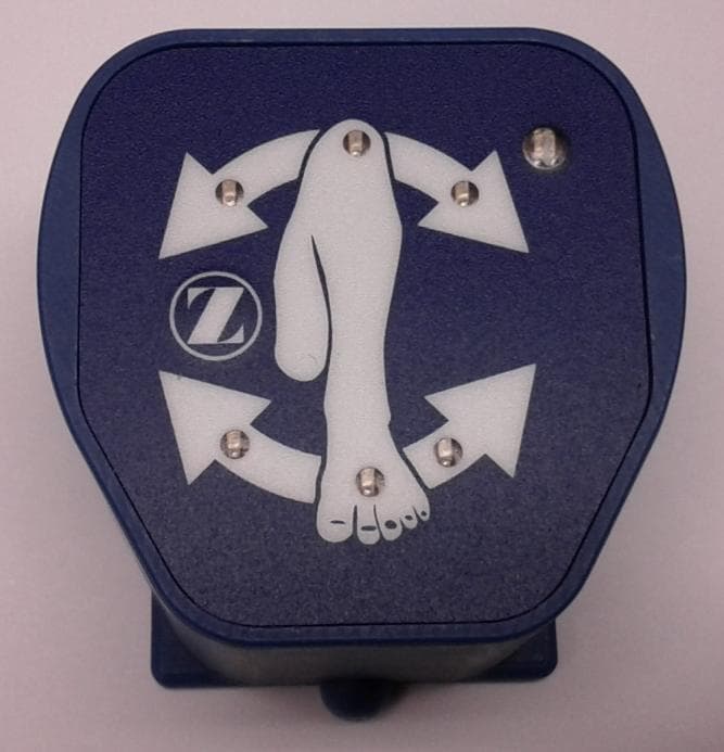
CVOR20S21A
Jun 03, 2012SmartTools Pod
Equipment Class
DTS - Digital Transmission System