D4CFJ007Wireless Alert
ZHUHAI FUJING TECHNOLOGY CO., LTD.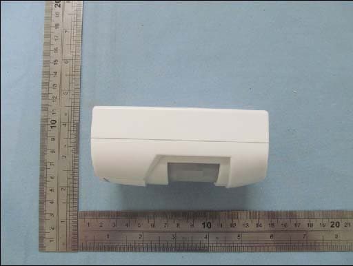
Click to zoom
Application Details
- Equipment Class
- DSC - Part 15 Security/Remote Control Transmitter
- Date of Grant
- May 29, 2012
- Application Purpose
- Original Equipment
- Date of Application
- May 29, 2012
- Equipment Note
- Wireless Alert
- Frequency Range
- 433.92000000 - 433.92000000
- Country
- China
Documents & Files
Document Text
Text extracted from the exhibit documents filed with the FCC. Open a document above to read the original.
Users Manual
ITEM FJ 007Wireless Alert Person or Vehicle FCC ID:D4CFJ007 Page 2 Sensor Receiver Power Switch (On Side) Figure A DC Jack (On Side) Components and Controls Setup Instructions Installing Batteries 1. Using a screwdriver (not included), remove the Battery Cover of the Sensor, and insert three AAA batteries (not included), positioning in the correct polarity as indicated in the battery compartment. Replace the Battery Cover. 2. Using a screwdriver (not included), remove the Battery Cover of the Receiver, and insert three C batteries (not included), positioning in the correct polarity as indicated in the battery compartment. Replace the Battery Cover. CAUTION: Position batteries in proper polarity and do not install batteries of different types, charge levels, or capacities together. Note: An optional 6 volt, 200 mA power adapter (not included) can be used to power the Receiver instead of batteries. Installing the Sensor and Receiver Determine the location of the Sensor and Receiver. Choose locations with no hidden wiring which would contact the mounting screws. 1. Considering the following when choosing a location for the Sensor: 2. Using hardware (not included), mount the Sensor securely to a flat surface. 3. Place the Receiver within 120m of the Sensor. a. The passive infrared sensor detects heat. Avoid aiming it towards areas that produce heat such as heater vents, windows where the sun hits, or outdoor spotlights. Note: Obstructions may reduce the receiving range. Page 3 b. Mount the Sensor at least 1m above the ground. If placed under the garage eaves, be sure that the Sensor is not blocked by the roof facia board. c. If placed above 2m high,the Sensor should be aimed downward so that it is pointed toward the area being monitored. 4. Mount the Receiver to a flat surface with hardware (not included), or stand on a flat surface. The receiver is not intended to be weather resistant. Note: Do not install the receiver in a location that will get wet or directly exposed to the elements. Operation Power Switch The Power Switch has three settings: a. Of f: Power is off. b. Low: A short beep will sound (approximately 80dB) and the LED will flash when motion is detected. c. Hi: A loud beep will sound (approximately 92dB) and the LED will flash when motion is detected. Operation 1. To operate the Driveway Alert, slide the Power Switch on the Receiver to the “Hi” setting. Allow 30 seconds for warm-up. Two short beeps will sound, indicating the unit is working. 2. Test the Sensor by walking or driving into the protected area. Another person should be listening for the alarm to sound. 3. If the Sensor does not activate, Sensor relocation or aiming adjustment will be required. 4. If the Receiver does not activate with the sensor, reposition them closer together. 5. Once you have determined that the unit is working properly, leave in the “Hi” setting or adjust to the “Low” setting. Low Battery 1. When the Sensor batteries need changing the LED on the Sensor will turn on. Replace the batteries. 2. When the Receiver batteries need changing, the center LED on the Receiver will turn on. Replace the batteries. CleaningMaintenance and Lubrication 1. BEFORE EACH USE, inspect the general condition of the tool. Check for: • leaking, swollen, or cracked batteries, • loose hardware, • misalignment or binding of parts, • cracked or broken parts, and • any other condition that may af fect its safe operation. 2. AFTER USE, wipe external surfaces of the tool with clean cloth. 3. Replace the batteries in the Receiver or Sensor when their low battery LED indicator lights. 4. There are no replaceable parts on the Receiver or Sensor units. Page 4 Parts List PartDescriptionQty 1Transmitter1 2Receiver1 PartDescriptionQty 3Assembly Hardware1 10. Do not overreach. Keep proper footing and balance at all times. If a ladder is to be used during installation, it should be supported by an assistant. 11. Do not set up the Alert System if under the influence of alcohol or drugs. Read warning labels on prescriptions to determine if your judgement or reflexes are impaired while taking drugs. If there is any doubt, do not set up the Light. 13. The warnings, precautions, and instructions discussed in this instruction manual cannot cover all possible conditions and situations that may occur. It must be understood by the operator that common sense and caution are factors which cannot be built into this product, but must be supplied by the operator. IMPORTANT SAFETY INFORMATION 1. Position batteries in proper polarity and do not install batteries of different types, charge levels, or capacities together. 2. Keep installation area clean. Cluttered areas invite accidents. 3. Observe installation area conditions. Keep work area well lit during installation. 4. Check for damaged parts. Before using any product, any part that appears damaged should be carefully checked to determine that it will operate properly and perform its intended function. Check for any broken or damaged parts and any other conditions that may af fect its operation. Replace or repair damaged or worn parts immediately. Do not use the Alert System if any switch does not turn on and off properly. 5. Replacement parts and accessories. When servicing, use only identical replacement parts. Use of any other parts will void the warranty. 6. Keep children away. Mount the Sensor and Receiver out of children’s reach. 7. Dress properly. Protective, electrically non-conductive clothes and nonskid footwear are recommended when working with the Alert System. Wear restrictive hair covering to contain long hair. 8. Use eye protection. Wear ANSI- approved impact safety goggles when setting up this product.12. Have your power tool serviced by a qualified repair person using only identical replacement parts. This will ensure that the safety of the power tool is maintained. 9. Maintain products with care. Keep the Alert System clean for better and safer performance. Inspect the components …
Text truncated - open the document above for the full version.
Cover Letter(s)
May Fe d Aut FCC Re: Pur s requ 1: B 2: C 3: O 4: P Th e rele app Th e all a app Sin c Ch Z H y 28, 2012 deral Comm thorization C ID: D4C : Confiden suant to Se uests confid Block Diagra Circuit Diagra Operational D Parts List e above mat ased to the licant and p e Applicant u accompanyi lication. cerely, uanxiang HUHAI FU 2 munication and Evalu FJ007 ntiality Re ctions 0.457 ential treatm m am Description terials conta e public. The rovide unjus understands ng docume n g Jiang /D UJING TE n Commiss uation Divis quest 7 and 0.459 ment of infor ain trade se e public dis stified benef that pursua ntation will Director ECHNOLO sion sion 9 of the Com rmation appl ecrets and p sclosure of t fits to its com nt to Rules 0 not be mad OGY CO mmission’s R ied this app proprietary these matte mpetitors. 0.457, disclo e before th ., LTD. Rules, the a lication as o information ers might be osure of this e date of th applicant he outlined belo not custom e harmful to s Application he Grant for ereby ow: marily o the n and r this
External Photos
TOP VIEW OF EUT BOTTOM VIEW OF EUT LEFT VIEW OF EUT RIGHT VIEW OF EUT FRONT VIEW OF EUT BACK VIEW OF EUT
ID Label/Location Info
DRIVEWAY / WIRELESS ALERT Model:FJ 007 FUJING TECH FCC ID: D4CFJ007 Made in China
Internal Photos
OPEN VIEW OF EUT FRONT VIEW OF PCB BACK VIEW OF PCB
Test Report
FCC Test Report Report No.: AGC21L120501‐1F2 FCC ID : D4CFJ007 PRODUCT DESIGNATION : DRIVEWAY / WIRELESS ALERT BRAND NAME : FUJING TECH TEST MODEL : FJ 007 CLIENT : ZHUHAI FUJING TECHNOLOGY CO., LTD. DATE OF ISSUE : May 21, 2012 STANDARD(S) : FCC Part 15 Rules REPORT VERSION : V1.0 Attestation of Global Compliance Co., Ltd. CAUTION: This report shall not be reproduced except in full without the written permission of the test laboratory and shall not be quoted out of context. Report No.: AGC21L120501-1F2 Page 1 of 24 TABLE OF CONTENTS 1. VERIFICATION OF COMPLIANCE ............................................................................................................... 3 2. GENERAL INFORMATION ............................................................................................................................ 4 2.1. PRODUCT DESCRIPTION FOR EQUIPMENT UNDER TEST (EUT) ........................................................ 4 2.2. TEST STANDARDS .................................................................................................................................... 4 2.3. RELATED SUBMITTAL(S)/GRANT(S) ........................................................................................................ 4 2.4. TEST METHODOLOGY .............................................................................................................................. 4 2.5. TEST FACILITY ........................................................................................................................................... 5 2.6. ACCESSORIES EQUIPMENT LIST AND DETAILS .................................................................................... 5 2.7. EUT PORT&CABLE LIST AND DETAILS .................................................................................................... 5 3. SUMMARY OF TEST RESULTS ................................................................................................................... 6 4. TEST MODES ................................................................................................................................................ 6 5. §15.203 ANTENNA REQUIREMENT ............................................................................................................. 7 5.1. STANDARD APPLICABLE .......................................................................................................................... 7 5.2. TEST RESULT ............................................................................................................................................ 7 6. §15.231 (A) DWELL TIME REQUIREMENT .................................................................................................. 8 6.1. DESCRIPTION OF REQUIREMENT .......................................................................................................... 8 6.2. TEST SET-UP (BLOCK DIAGRAM OF CONFIGURATION) ........................................................................ 8 6.3. MEASUREMENT PROCEDURE ................................................................................................................. 8 6.4. TEST RESULT ............................................................................................................................................ 8 7. §15.209, §15.231 (B) RADIATED EMISSION REQUIREMENT .................................................................. 10 Report No.: AGC21L120501-1F2 Page 2 of 24 7.1. STANDARD APPLICABLE AND LIMITS ................................................................................................... 10 7.2. TEST EQUIPMENT LIST AND DETAILS .................................................................................................... 11 7.3. TEST PROCEDURE ................................................................................................................................. 12 7.4. TEST SET-UP (BLOCK DIAGRAM OF CONFIGURATION) ...................................................................... 13 7.5. TEST RESULTS/PLOTS ........................................................................................................................... 14 8. §15.231 (C) 20 DB BANDWIDTH REQUIREMENT ..................................................................................... 17 8.1. STANDARD APPLICABLE ........................................................................................................................ 17 8.2. TEST EQUIPMENT LIST AND DETAILS ................................................................................................... 17 8.3. TEST PROCEDURE ................................................................................................................................. 17 8.4. SUMMARY OF TEST RESULTS/PLOTS .................................................................................................. 17 APPENDIX 1 .................................................................................................................................................... 19 PHOTOGRAPHS OF TEST SETUP ................................................................................................................ 19 APPENDIX 2 .................................................................................................................................................... 20 PHOTOGRAPHS OF EUT ............................................................................................................................... 20 APPENDIX 3 .................................................................................................................................................... 23 INTERNAL PHOTOGRAPHS OF EUT ............................................................................................................ 23 Report No.: AGC21L120501-1F2 Page 3 of 24 1. VERIFICATION OF COMPLIANCE Applicant: ZHUHAI FUJING TECHNOLOGY CO., LTD. Applicant Address: F4 ZHULONG INDUSTRY BLDG. GUANGSHENG, NANPING, ZHUHAI CITY, C…
Text truncated - open the document above for the full version.
Test Setup Photos
Radiated Emission Test Setup (30MHz-1000MHz)
Contact Information
Applicant
Chuanxiang Jiang
Test Firm
Attestation of Global Compliance Shenzhen Co. Ltd.Forrest Lei
Technical Specifications
| # | Rule Parts | Frequency Range | Power Output |
|---|---|---|---|
| 1 | 15.231 | 433.92 MHz - 433.92 MHz | - |
Other Applications from ZHUHAI FUJING TECHNOLOGY CO., LTD.

D4CFJ007B
Jul 04, 2013Wireless Alarm
Equipment Class
DSC - Part 15 Security/Remote Control Transmitter