DBDZLYNK23558XGarrett Vortex
Garrett Metal Detectors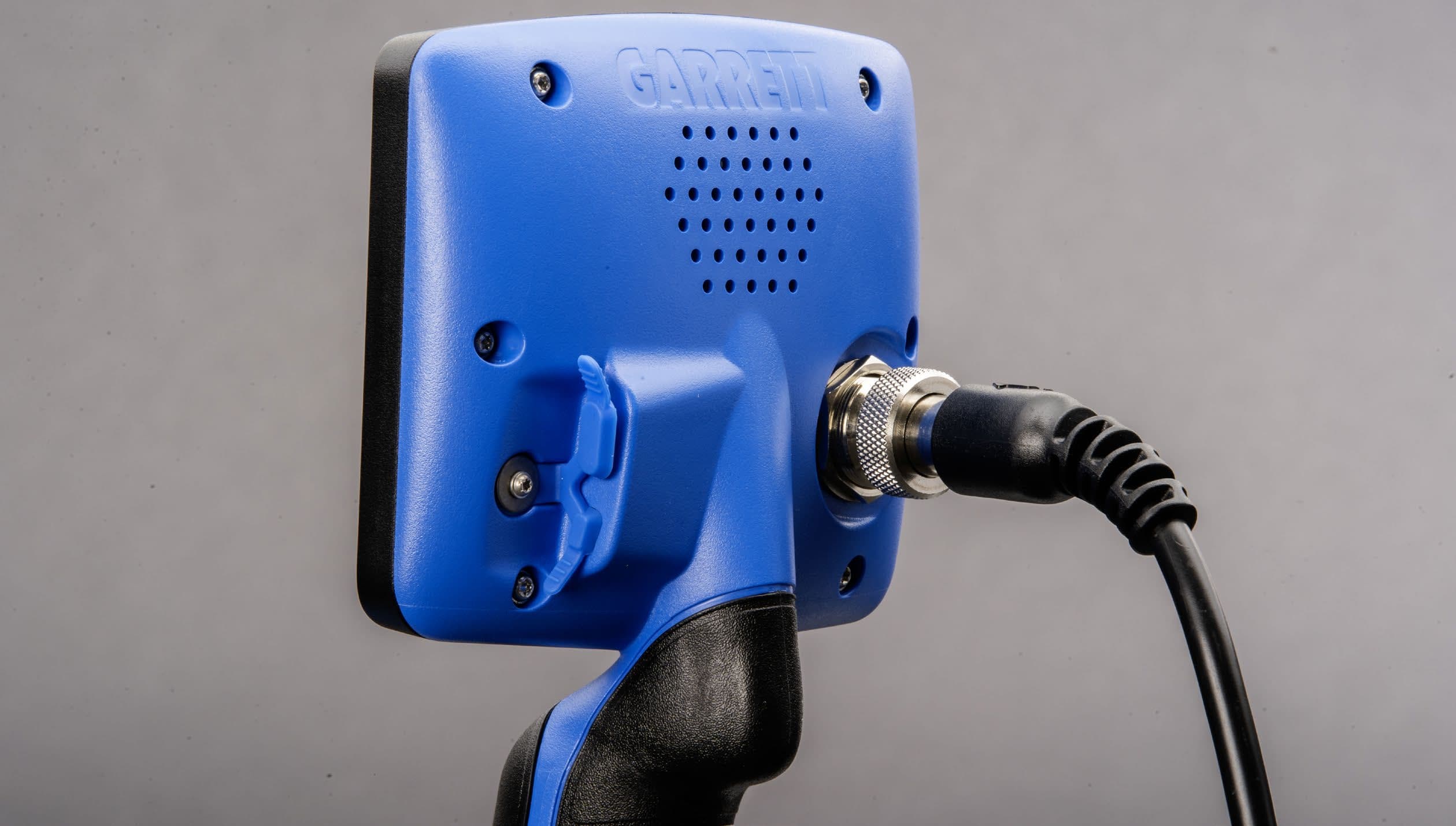
Click to zoom
Application Details
- Equipment Class
- DTS - Digital Transmission System
- Date of Grant
- Jul 21, 2024
- Application Purpose
- Original Equipment
- Date of Application
- Jul 21, 2024
- Equipment Note
- Garrett Vortex
- Frequency Range
- 2406.00000000 - 2474.00000000
- Company
- Garrett Metal Detectors
- Country
- United States
Documents & Files
Document Text
Text extracted from the exhibit documents filed with the FCC. Open a document above to read the original.
Users Manual
Quick Start Guide ASSEMBLY CHARGING This device complies with part 15 of the FCC Rules. Operation is subject to the following two conditions: (1) This device may not cause harmful interference, and (2) this device must accept any interference received, including interference that may cause undesired operation. Changes or modifications not expressly approved by the party responsible for compliance could void the user’s authority to operate the equipment. This device complies with Industry Canada license-exempt RSS standard(s). Operation is subject to the following two conditions: (1) this device may not cause interference, and (2) this device must accept any interference, including interference that may cause undesired operation of the device. Ce produit est conforme aux normes RSS exemptes de licence d’Industry Canada. Son fonctionnement est soumis aux deux conditions suivantes : (1) ce dispositif ne peut pas provoquer d’interférences et (2) ce dispositif doit accepter toute interférence, y compris celles pouvant entraîner un dysfonctionnement. Wireless Transmitter Specifications Audio Delay: 17 milliseconds Audio Bandwidth: 30-18,000 Hz Operating Frequency: 2406–2474 MHz Transmit Power: 8.6 dBm EIRP Certifications: FCC, CE, IC, AS/NZ Loosen upper camlock and extend stem until pin locks into first pin position. Hand-tighten upper camlock. (Note: second pin position can be used to extend stem length.) 2nd pin 1st pin Insert rubber washers, connect searchcoil to the stem as shown, and hand-tighten the wing nut. REGULATORY INFORMATION / INFORMACIÓN NORMATIVA / INFORMATIONS RÉGLEMENTAIRES © 2024 Garrett Electronics, Inc. PN 1559200.A.0624 EC#00000 Visit Garrett.com to download full-length Vortex User’s manuals. Insert USB-C behind control box to charge unit. Recharges in about 4 hours. For fastest charging, use a 10W (2A) or greater power source. Adjust arm cuff, if needed. Loosen lower camlock and extend stem to desired operating length. Hand-tighten the camlock. Wrap cable around stem and attach. QUICK START Step 1 Power on. Press and release. Vortex powers on in last mode used and is ready to search. 0 0 40 39 99 39 ZERO M-FREQ 83 1 2 3 4 Step 2 Select Mode. Tap Mode button to select a different detection mode, if desired. Step 3 Adjust settings. Press Menu button to access all settings. Scroll up or down using the and arrows. Tap Plus (+) or Minus (-) button to adjust selected setting. Step 4 Ground Balance Press and hold Ground Balance button while bouncing coil above the ground until ground response disappears or becomes as small as possible. 1-2 inch (2-3cm)1-2 inch (2-3cm) 3 ft/sec (1m/s)3 ft/sec (1m/s) CORRECT SWING FPO Wireless Headphones - Flashes while attempting to pair, solid when paired. Available on VX7 and VX9 models. Notch Discrim - Use to eliminate areas of Target ID from audible detection. Use and arrows to move between Target ID scales and the Plus (+) or Minus (-) buttons to move cursor along each scale. Tap Ground Balance button to accept or reject a notch. 3. Ground Balance—Hold down while bouncing coil above ground until ground response disappears or becomes as small as possible. Also used during Notch Discrim adjustments. 4. Pinpoint—Hold for pinpointing function, to precisely locate targets. 1. Power, Mode, Exit, and Factory Reset—Hold 1 second for power ON or OFF. Quick-press to change Modes or to exit MENU settings. Press and hold 5 seconds to restore Factory Settings. 2. MENU/Settings— Press once to enter Menu items. Use and arrows to scroll up or down through different settings. Use the Plus (+) or Minus (-) buttons to change setting. Sensitivity - Indicates current Sensitivity setting. Volume - Overall volume control setting for headphones and built-in speaker. Iron Audio - Allows the user to hear discriminated iron. Iron Volume - Select 1-8 to adjust the volume of iron/ferrous targets, while volume of non-ferrous targets remains at normal level. Frequency Options - VX5: Multi-Frequency (Multi-Freq.) and 13kHz VX7: Multi-Freq., Multi-Salt, 5kHz, and 13kHz VX9: Multi-Freq., Multi-Salt, 5kHz, 9kHz, 13kHz, 18kHz, and 25kHz Channel - Select 1-8 to eliminate electrical interference. Recovery Speed - Select 1- 3 on VX9 to control target reactivity/separation. Two speeds on VX7. Fixed recovery speed on VX5. Backlight - Turn on to illuminate LCD. 0 0 40 39 99 39 ZERO M-FREQ 83 1 2 3 4 CONTROLS FACTORY DEFAULT SETTINGS Mode: Standard Sensitivity: 6 Volume: 8 Iron Audio: OFF Iron Volume: 4 Frequency: Multi-Freq. Channel: 4 Recovery Speed: 1 Backlight: Off Wireless: Off SEARCH MODES Zero Discrimination Beach* Standard Thin Coins** US Coins Fast** Custom * Available only on VX7 and VX9 models. ** Available only on VX9 model. Detects every type of metal. All discrimi- nation pixels are switched on. No metal targets have been notched out (eliminat- ed). Use this mode to find all metal items or when the material of the desired object is unknown. Enhanced audio on targets within a select Target ID range, such as gold coins, small Roman coins, and thin, hammered coins. Audio volume is suppressed for common ferrous targets and for highly conductive targets. Increased Reaction speed and suppressed audio volume on common ferrous targets. Ideal for use in competition hunts and for high-trash areas. Most iron targets are notched out. This mode is ideal for locating relics, jewelry, and most international coins. Designed to find U.S. and similar coins, and to eliminate common trash items such as iron, foil, and pull-tabs. Settings programmed by the user are retained when the detector is switched off. Factory preset is Standard Mode. By default, Beach Mode operates only in the Multi-Salt frequency setting. Iron Discrimination is set to eliminatine most common ferrous items from detection. 1 2 3 4 5 6789 10 1. Target Scale—Single-tier Target ID scale indicates both ferrous and non-ferrous targets, with ferrous targets indicating towards the left, low conductivity in the middle…
Text truncated - open the document above for the full version.
Attestation Statements
1881 W. State Street | Garland, TX USA 75042 | (972) 494-6151 | garrett.com TO: Federal Communications Commission Authorization and Evaluation Division 7435 Oakland Mills Road Columbia, Maryland 21046 Re: section 2.911(d)(7) filing To whom it may concern, This letter is to confirm that Robert Podhrasky has accepted responsibility to act as the agent for service of process as acknowledged by the applicant, Robert Podhrasky. The U.S. Agent further agrees to the obligations defined in the current version of FCC guidance document, KDB 986446. U.S. Agent: Robert Podhrasky Title: Sr. Vice President, Director of Engineering Company Name: Garrett Electronics Inc. Address: 1881 W. State Street Telephone No: 972.797.9693 Email: [email protected] FRN (FCC Registration Number for applicant) 0024675837 FRN (FCC Registration Number for U.S. Agent (if available): N/A The applicant accepts and acknowledges the obligation to maintain an agent for no less than one year after the grantee has terminated all marketing and importation or the conclusion of any Commission- related proceeding involving the equipment. If the U.S. Agent is a test lab or TCB, the entity attests that procedures have been put into place to ensure that the entity remains impartial as defined in ISO 17025 or 17065, as applicable. Signature of Applicant (must be signed by either the contact of record in the FCC database for the applicant grantee code or authorized agent/employee): Signature of U.S. Agent (if different from applicant): Name: Name: Date: 18 June, 2024 Date:
Attestation Statements
1881 W. State Street | Garland, TX USA 75042 | (972) 494-6151 | garrett.com Date: June 18, 2024 Federal Communications Commission Authorization and Evaluation Division 7435 Oakland Mills Road Columbia, Maryland 21046 Re: Attestation regarding ‘covered’ equipment and the Covered List FCC ID: DBDZLYNK23558X To whom it may concern, Per 2.911(d)(5)(i), Garrett Electronics Inc. certifies that the equipment for which authorization is sought is not “covered” equipment prohibited from receiving an equipment authorization pursuant to section 2.903 of the FCC rules. Per 2.911(d)(5)(ii), Garrett Electronics Inc. certifies that, as of the date of the filing of the application, the applicant is not identified on the Covered List as an entity producing “covered” equipment. Sincerely, Robert Podhrasky Sr. Vice President Director of Engineering
Cover Letter(s)
June 4, 2024 Federal Communications Commission 445 12 th Street SW Washington, DC 20554 Subject: Cover Letter for FCC application for Certification To whom it may concern: This Garrett Vortex metal detector contains a Garrett Z-Lynk Wireless Digital Transmission System operating in the 2.4GHz ISM band. It is used with Garrett Metal Detectors’ line of Z-Lynk Wireless headphones and the Garrett Model WR-1 Receiver. It is powered by a rechargeable 3.6 volt battery and transmits audio data from the detector via a wireless link to the Garrett Z-Lynk equipped receiver. . This is to seek an original Certification on the Garrett Vortex as compliant with FCC 15.247. FCC ID: DBDZLYNK23558X Sincerely, Robert Podhrasky Sr. Vice President
Cover Letter(s)
June 4, 2024 Federal Communications Commission Authorization and Evaluation Division 7435 Oakland Mills Road Columbia, Maryland 21046 Re: Request for confidentiality FCC ID: DBDZLYNK23558X To whom it may concern, We hereby respectfully request that under the provision of 47 CFR 0.459 and 0.457(d) the documents listed below and attached with this application for certification be provided with Long-Term confidential status. • Schematics.pdf • Operational Description.pdf • Frequency Block Diagrams.pdf Any exhibit / information for which we have requested confidentiality, but which may not be accorded such treatment by the FCC, should be returned to us. The documents listed above contain trade secrets that are treated as confidential by us. Substantial competitive harm to us could result should they be made available to the public. Sincerely, Robert Podhrasky Sr. Vice President Director of Engineering
External Photos
GARRETT VORTEX EXTERNAL PHOTOS
ID Label/Location Info
Vortex Label and Location
Internal Photos
GARRETT VORTEX™ Internal Photos June 18, 2024 GARRETT VORTEX™ Internal Photos June 18, 2024 GARRETT VORTEX™ Internal Photos June 18, 2024
Parts List/Tune Up Info
Vortex RF Radio Bill of Materials DesignatorDescription C73,C7418pF 5% 50V NPO 0402 C82220pF 5% 50V NPO 0402 C87, C1080.01uF 5% 25V X7R 0402 C76, C77, C78, C79, C80, C81, C83, C850.1uF 10% 25V X7R 0402 C861uF 10% 16V X7R 0603 C71, C842.2uF 20% 16V X7R 0603 C10710uF 10% 25V X7R 1210 C3910uF 20% 16V TNT 3528 C7522uF 20% 10V X5R 0603 C3822uF 20% 25V X5R 0805 L81uH 20% 2520 R69, R78, R7910.0K ohm 1% 1/16W 0402 R2256K ohm 5% 1/16W 0402 R12991.0K ohm 1% 1/16W 0402 R88100.0K ohm 1% 1/16W 0402 R128560K ohm 5% 1/16W 0402 Y1ABM11-48.000MHZ-N7G-T3 BAL1Johanson Technology 2450BM15A0002E U17Texas Instruments CC8520RHAT U25Texas Instruments LP5907MFX-3.3/NOPB U24TPS631000DRLR C72No Load R37No Load L2No Load, shorted pad J5No Load
RF Exposure Info
This report must not be used to claim product certification, approval, or endorsement by A2LA, NIST, or any agency of the U.S. Government. This Report shall not be reproduced, except in full without written approval of the laboratory. Garrett Metal Detectors Vortex FCC 2.1093:2024 DTS Inductive Report: GARR0125.1 Rev. 0, Issue Date: July 15, 2024 TABLE OF CONTENTS 2023.04.17 Section Page Number Certificate of Evaluation .................................................................................. 3 Revision History .............................................................................................. 4 Accreditations .................................................................................................. 5 Facilities .......................................................................................................... 6 Product Description ......................................................................................... 7 Exposure Condition ......................................................................................... 8 SAR Test Exclusion ........................................................................................ 9 Appendix ......................................................................................................... 11 Vortex Radio Transmit Duty Cycle Analysis .................................................... 12 End of Report .................................................................................................. 13 Report No. GARR0125.12/13 CERTIFICATE OF EVALUATION 2018-09-14 Product compliance is the responsibility of the client; therefore, the tests and equipment modes of operation represented in this report were agreed upon by the client, prior to testing. The results of this test pertain only to the sample(s) tested. The specific description is noted in each of the individual sections of the test report supporting this certificate of test. This report reflects only those tests from the referenced standards shown in the certificate of test. It does not include inspection or verification of labels, identification, marking or user information. As indicated in the Statement of Work sent with the quotation, Element’s standard process is to always use the latest published version of the test methods even when earlier versions are cited in the test specification. Issuance of a purchase order was de facto acceptance of this approach. Otherwise, the client would have advised Element in writing of the specific version of the test methods they wanted applied to the subject testing Last Date of Evaluation: July 11, 2024 Garrett Metal Detectors EUT: Vortex RF Exposure Evaluation Standards Specification Method FCC 2.1093:2024 FCC 447498 D01 General RF Exposure Guidance v06 Results Method Clause Description Applied Results Comments 4.3.1 SAR Test Exclusion Yes Pass None Deviations From Evaluation Standards None Approved By: Donald Facteau, Process Architect Report No. GARR0125.13/13 REVISION HISTORY 2018.07.17 Revision Number Description Date (yyyy-mm-dd) Page Number 00 None Report No. GARR0125.14/13 ACCREDITATIONS AND AUTHORIZATIONS 2021.09.01 United States FCC - Designated by the FCC as a Telecommunications Certification Body (TCB). Certification chambers, Open Area Test Sites, and conducted measurement facilities are listed with the FCC. A2LA - Each laboratory is accredited by A2LA to ISO / IEC 17025, and as a product certifier to ISO / IEC 17065 which allows Element to certify transmitters to FCC and IC specifications. Canada ISED - Recognized by Innovation, Science and Economic Development Canada as a Certification Body (CB) and as a CAB for the acceptance of test data. European Union European Commission – Recognized as an EU Notified Body validated for the EMCD and RED Directives. United Kingdom BEIS – Recognized by the UK as an Approved Body under the UK Radio Equipment and UK EMC Regulations. Australia/New Zealand ACMA - Recognized by ACMA as a CAB for the acceptance of test data. Korea MSIT / RRA - Recognized by KCC’s RRA as a CAB for the acceptance of test data. Japan VCCI - Associate Member of the VCCI. Conducted and radiated measurement facilities are registered. Taiwan BSMI – Recognized by BSMI as a CAB for the acceptance of test data. NCC - Recognized by NCC as a CAB for the acceptance of test data. Singapore IDA – Recognized by IDA as a CAB for the acceptance of test data. Israel MOC – Recognized by MOC as a CAB for the acceptance of test data. Hong Kong OFCA – Recognized by OFCA as a CAB for the acceptance of test data. Vietnam MIC – Recognized by MIC as a CAB for the acceptance of test data. SCOPE For details on the Scopes of our Accreditations, please visit: California Minnesota Oregon Texas Washington Report No. GARR0125.15/13 FACILITIES 2023.09.21 Testing was performed at the following location(s) Location Labs (1) Address A2LA (2) ISED (3) BSMI (4) VCCI (5) CAB (6) FDA (7) ☐ California OC01-17 41 Tesla Irvine, CA 92618 (949) 861-8918 3310.04 2834B SL2-IN-E-1154R A-0029 US0158 TL-55 ☐ Minnesota MN01-11 9349 W Broadway Ave. Brooklyn Park, MN 55445 (612) 638-5136 3310.05 2834E SL2-IN-E-1152R A-0109 US0175 TL-57 ☒ Oregon EV01-12 6775 NE Evergreen Pkwy #400 Hillsboro, OR 97124 (503) 844-4066 3310.02 2834D SL2-IN-E-1017 A-0108 US0017 TL-56 ☐ Plano Texas PT01-15 1701 E Plano Pkwy, Ste 150 Plano, TX 75074 (972) 509-2566 214.19 US0054 ☐ Texas TX01-09 3801 E Plano Pkwy Plano, TX 75074 (469) 304-5255 3310.03 2834G SL2-IN-E-1158R A-0201 US0191 TL-54 ☐ Washington NC01-05 19201 120th Ave NE Bothell, WA 98011 (425) 984-6600 3310.06 2834F SL2-IN-E-1153R A-0110 US0157 TL-67 ☐ Offsite N/A See Product Description N/A N/A N/A N/A N/A N/A See data sheets for specific labs (1) The lab designations denote individual rooms within each location. (OC01, OC02, OC03, etc.) (2) A2LA Certificate No. (3) ISED Company No. (4) BSMI No. (5) VCCI Site Filing No. (6) CAB Identifier. Recognized Phase I CAB for ISED, ACMA, BSMI, I…
Text truncated - open the document above for the full version.
Test Report
Garrett Vortex Low Frequency Inductive Loop Antenna Description Transmitter Antenna 4.5 x 10.25 inch air core 38 turns of 22 Awg Mag Wire Inductance 0.61 mH Receiver Antenna 4.5 x 10.25 inch air core 83 turns of 30 Awg Mag Wire Inductance 3.55 mH Transmitter and Receiver Antennas are co-located
Test Report
Antenna Description Garrett Vortex Inverted F Antenna designed in accordance with Texas Instruments Design Note SWRU120D Maximum Gain is 3.3 dBi.
Test Report
Application Report 2.4-GHz Inverted F Antenna ABSTRACT This document describes a printed-circuit board (PCB) antenna design that can be used with all 2.4-GHz transceivers and transmitters from Texas Instruments ™ . The maximum gain when used on the reference board is measured to be +3.3 dBi, and the overall size requirements for this antenna are 25.7 × 7.5 mm (not including ground plane). Table of Contents 1 Description of the antenna Design........................................................................................................................................2 2 Measurement Results.............................................................................................................................................................3 2.1 Radiation Pattern...............................................................................................................................................................3 2.2 Reflection.........................................................................................................................................................................10 2.3 Bandwidth.........................................................................................................................................................................11 3 Summary................................................................................................................................................................................11 4 References.............................................................................................................................................................................11 5 Revision History...................................................................................................................................................................12 Trademarks Texas Instruments ™ is a trademark of Texas Instruments. All trademarks are the property of their respective owners. www.ti.comTable of Contents SWRU120D – APRIL 2007 – REVISED JANUARY 2019 Submit Document Feedback 2.4-GHz Inverted F Antenna1 Copyright © 2021 Texas Instruments Incorporated 1 Description of the antenna Design It is important to make an exact copy of the antenna dimensions to obtain optimum performance. The easiest approach to implement the antenna in a PCB CAD tool is to import the antenna layout from a gerber file or a DXF file. Such files are included in CC2430DB reference design [1]. The gerber file is called Inverted_F_Antenna.spl and the DXF file is called Inverted_F_Antenna.dxf. If the antenna is implemented on a PCB that is wider than the antenna, avoid placing components or having a ground plane close to the end points of the antenna. If the CAD tool being used does not support importing gerber or DXF files, see Figure 1-1 and Table 1-1. The antenna impedance is tuned to 50 ohm on the reference board. The impedance will however be affected by different size and shape of the ground plane, objects in the antenna nearfield such as mechanical assemblies (housing, batteries, etc.), PCB thickness, PCB material and so on. It is therefore recommended to add a pi-network close to the antenna feedpoint for impedance matching. The results presented in this document are based on an antenna implemented on a PCB with a 1-mm thickness using standard FR-4 material. Figure 1-1. IFA Dimensions Table 1-1. IFA Dimensions H15.70 mmW20.46 mm H20.74 mmL125.58 mm H31.29 mmL216.40 mm H42.21 mmL32.18 mm H50.66 mmL44.80 mm H61.21 mmL51.00 mm H70.80 mmL61.00 mm H81.80 mmL73.20 mm H90.61 mmL80.45 mm W11.21 mm Description of the antenna Designwww.ti.com 22.4-GHz Inverted F AntennaSWRU120D – APRIL 2007 – REVISED JANUARY 2019 Submit Document Feedback Copyright © 2021 Texas Instruments Incorporated 2 Measurement Results All of the results presented in this section are based on measurements performed with the CC2430DB [1] evaluation board. 2.1 Radiation Pattern Figure 2-1 shows how to relate all of the radiation patterns to the orientation of the antenna. The radiation patterns were measured with the CC2430 device programmed to 0-dBm output power. Figure 2-1. Relating Antenna to Radiation Patterns www.ti.comMeasurement Results SWRU120D – APRIL 2007 – REVISED JANUARY 2019 Submit Document Feedback 2.4-GHz Inverted F Antenna3 Copyright © 2021 Texas Instruments Incorporated Figure 2-2 shows the XY plane vertical polarization. Figure 2-2. XY Plane–Vertical Polarization Measurement Resultswww.ti.com 42.4-GHz Inverted F AntennaSWRU120D – APRIL 2007 – REVISED JANUARY 2019 Submit Document Feedback Copyright © 2021 Texas Instruments Incorporated Figure 2-3 shows the XY plane horizontal polarization. Figure 2-3. XY Plane–Horizontal Polarization www.ti.comMeasurement Results SWRU120D – APRIL 2007 – REVISED JANUARY 2019 Submit Document Feedback 2.4-GHz Inverted F Antenna5 Copyright © 2021 Texas Instruments Incorporated Figure 2-4 shows the XZ plane vertical polarization. Figure 2-4. XZ Plane–Vertical Polarization Measurement Resultswww.ti.com 62.4-GHz Inverted F AntennaSWRU120D – APRIL 2007 – REVISED JANUARY 2019 Submit Document Feedback Copyright © 2021 Texas Instruments Incorporated Figure 2-5 shows the XZ plane horizontal polarization. Figure 2-5. XZ Plane–Horizontal Polarization www.ti.comMeasurement Results SWRU120D – APRIL 2007 – REVISED JANUARY 2019 Submit Document Feedback 2.4-GHz Inverted F Antenna7 Copyright © 2021 Texas Instruments Incorporated Figure 2-6 shows the YZ plane vertical polarization. Figure 2-6. YZ Plane–Vertical Polarization Measurement Resultswww.ti.com 82.4-GHz Inverted F AntennaSWRU120D – APRIL 2007 – REVISED JANUARY 2019 Submit Document Feedback Copyright © 2021 Texas Instruments Incorporated Figure 2-7 shows the YZ plane horizontal polarization. Figure 2-7. YZ Plane–Horizontal Polarization www.ti.comMeasurement Results SWRU120D – APRIL 2007 – REVISED JANUARY 2019 Submit Document Feedback 2.4-GHz Inverted F Antenna9 Copyright © 202…
Text truncated - open the document above for the full version.
Test Report
This report must not be used to claim product certification, approval, or endorsement by A2LA or any agency of the U.S. Government. This Report shall not be reproduced, except in full without written approval of the laboratory. Garrett Metal Detectors Vortex FCC 15.247:2024 RSS-Gen Issue 5:2018+A1:2019+A2:2021 RSS-247 Issue 3:2023 Low Power (SRD) DTS transceiver Report: GARR0125.0 Rev. 0, Issue Date: July 8, 2024 TABLE OF CONTENTS 2023.04.17 Section Page Number Certificate of Test ............................................................................................ 3 Revision History .............................................................................................. 5 Accreditations .................................................................................................. 6 Facilities .......................................................................................................... 7 Measurement Uncertainty ............................................................................... 8 Test Setup Block Diagrams ............................................................................. 9 Product Description ......................................................................................... 12 Power Settings and Antenna Information ........................................................ 13 Configurations ................................................................................................. 14 Modifications ................................................................................................... 15 Spurious Radiated Emissions ......................................................................... 16 Duty Cycle ....................................................................................................... 25 Output Power .................................................................................................. 26 Equivalent Isotropic Radiated Power (EIRP) ................................................... 29 Band Edge Compliance .................................................................................. 31 DTS Bandwidth (6 dB) .................................................................................... 34 Occupied Bandwidth (99%) ............................................................................. 37 Spurious Conducted Emissions ...................................................................... 40 Power Spectral Density ................................................................................... 44 End of Report .................................................................................................. 47 Report No. GARR0125.02/47 CERTIFICATE OF TEST 2022.04.01 Product compliance is the responsibility of the client; therefore, the tests and equipment modes of operation represented in this report were agreed upon by the client, prior to testing. The results of this test pertain only to the sample(s) tested. The specific description is noted in each of the individual sections of the test report supporting this certificate of test. This report reflects only those tests from the referenced standards shown in the certificate of test. It does not include inspection or verification of labels, identification, marking or user information. As indicated in the Statement of Work sent with the quotation, Element’s standard process is to always use the latest published version of the test methods even when earlier versions are cited in the test specification. Issuance of a purchase order was de facto acceptance of this approach. Otherwise, the client would have advised Element in writing of the specific version of the test methods they wanted applied to the subject testing. Last Date of Test: July 2, 2024 Garrett Metal Detectors EUT: Vortex Radio Equipment Testing Standards Specification Method FCC 15.247:2024 ANSI C63.10:2013 RSS-Gen Issue 5:2018+A1:2019+A2:2021 RSS-247 Issue 3:2023 Guidance FCC KDB 558074 v05r02:2019 Results Test Description Result FCC Section(s) RSS Section(s) ANSI C63.10 Section(s) Comments Powerline Conducted Emissions (Transmitter) N/A 15.207 RSS-Gen 8.8 6.2 Not required for a battery powered EUT. Spurious Radiated Emissions Pass 15.247(d), KDB 558074 -8.6, 8.7 RSS-247 5.5 6.5, 6.6, 11.12.1, 11.13.2 Duty Cycle N/A 15.247, KDB 558074 -6.0 RSS-Gen 3.2 11.6 Duty Cycle at 100% - Characterization of radio operation Output Power Pass 15.247(b), KDB 558074 -8.3 RSS-247 5.4(d) 11.9.1.1 Equivalent Isotropic Radiated Power (EIRP) Pass 15.247(b), KDB 558074 -8.3 RSS-247 5.4(d) 11.9.1.1 Band Edge Compliance Pass 15.247(d), KDB 558074 -8.5 RSS-247 5.5 11.11 DTS Bandwidth (6 dB) Pass 15.247(a), KDB 558074 -8.2 RSS-247 5.2(a) 11.8.2 Occupied Bandwidth (99%) Pass KDB 558074 - 2.1 RSS-Gen 6.7 6.9.3 Spurious Conducted Emissions Pass 15.247(d), KDB 558074 -8.5 RSS-247 5.5 11.11 Power Spectral Density Pass 15.247(e), KDB 558074 -8.4 RSS-247 5.2(b) 11.10.2 Powerline Conducted Emissions (Receiver) N/A 15.101, 15.107 RSS-Gen 5.2 ANSI C63.4 - 12.2.4 Not included per FCC 15.101 as this will be covered under SDoC rules for the FCC. RSS-Gen section 7 stated receiver requirements only apply to standalone receivers operating in the 30-960 MHz band and this is not a standalone receiver. Report No. GARR0125.03/47 CERTIFICATE OF TEST 2022.04.01 Product compliance is the responsibility of the client; therefore, the tests and equipment modes of operation represented in this report were agreed upon by the client, prior to testing. The results of this test pertain only to the sample(s) tested. The specific description is noted in each of the individual sections of the test report supporting this certificate of test. This report reflects only those tests from the referenced standards shown in the certificate of test. It does not include inspection or verification of labels, identification, marking or user information. As indicated in the Statement of Work sent with the quotation, Element’s sta…
Text truncated - open the document above for the full version.
Test Setup Photos
Test Setup Photos WTD.2024.01.16.0 Direct Connect Test Setup Photos WTD.2024.01.16.0 Spurious Radiated Emissions Test Setup Photos WTD.2024.01.16.0 EUT on Side EUT on Side Test Setup Photos WTD.2024.01.16.0 EUT Horz EUT Horz Test Setup Photos WTD.2024.01.16.0 EUT Vert EUT Vert Test Setup Photos WTD.2024.01.16.0
Contact Information
Applicant
Bob Podhrasky
Test Firm
Element Materials Technology Portland - EvergreenRenee Walker
[email protected]5038444066
Technical Specifications
| # | Rule Parts | Frequency Range | Power Output |
|---|---|---|---|
| 1 | 15C | 2.41 GHz - 2.47 GHz | 4.00 mW |