DD4-SR7XWWireless Receiver
Shure Incorporated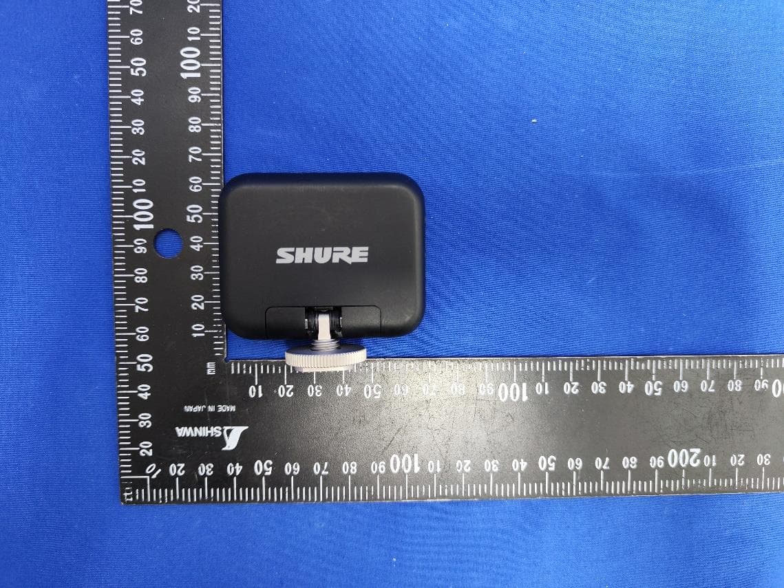
Click to zoom
Application Details
- Equipment Class
- DTS - Digital Transmission System
- Date of Grant
- Sep 13, 2023
- Application Purpose
- Original Equipment
- Date of Application
- Sep 13, 2023
- Equipment Note
- Wireless Receiver
- Frequency Range
- 2402.00000000 - 2480.00000000
- Company
- Shure Incorporated
- Country
- United States
Documents & Files
Document Text
Text extracted from the exhibit documents filed with the FCC. Open a document above to read the original.
Users Manual
QUICK S T A R T GUIDE M OVEMIC RECEIVER Printed in China Full user guide available on shure.com, or scan the QR code for more help. 27A53828 Battery Icon Channel 1 Channel 2 Live Meters Name lavs (Mic 1, Mic 2) in menu on MoveMic Receiver. Adjust and set gain for each microphone. Note, you may need different gain for each mic depending on the subject you are recording. Check live meters on MoveMic Receiver home screen to ensure you’re passing audio. You’re ready; start recording on your phone or camera. 1 2 3 4 Top Tip: Adjust the gain for each microphone so the loudest peaks are in the yellow on the meter for the best sound. .. ) © 2023 Shure Incorporated. SHURE and the SHURE logotype are registered trademarks of Shure Incorporated or Shure Acquisition Holdings, Inc. For additional information, see shure.com/trademarks. Patents: shure.com/patents CONNECTPAIRING CAMERAPHONE PAIRING MODE REMOVE Use supplied 3.5mm – 3.5mm cable to connect MoveMic Receiver to your camera or DSLR. Mount MoveMic Receiver onto the cold shoe on the top of your camera. Use supplied USB-C – USB-C cable to connect your MoveMic Receiver to the USB-C port on your phone. Note, using MoveMic Receiver (wired) will give you additional compatibility to third party apps in comparison to using your MoveMic products via Bluetooth. Bluetooth is only recommended for use with ShurePlus MOTIV apps and approved apps. Phone mount sold separately. USB-C – Lightning sold separately for Lightning iPhones. 1 Important: Ensure MoveMic lavalier mics and MoveMic Receiver are charged before use. Remove microphone(s) from Charge Case and put in pairing mode by holding button for 6 seconds. Navigate to ‘My Device’ menu and select ‘Connect New Mic’. 3 Click on the MoveMic lavalier microphone(s) within the 'My Device' menu to pair 2 MOVEMIC TM WIRELESS OWNERS MANUAL Product Safety and Warranty Information Printed in China ©2023 Shure Incorporated 27A53826 (Rev. 1) MoveMic-OM.indb 1MoveMic-OM.indb 18/18/2023 1:53:25 PM8/18/2023 1:53:25 PM 2 Regulatory Model: North America, South America, Russia | Wireless Lavalier Microphone: SC7LW Wireless Receiver: SR7XW Rest of World | Wireless Lavalier Microphone: SC6LW Wireless Receiver: SR6XW Charge Case : SPCCW MoveMic-OM.indb 2MoveMic-OM.indb 28/18/2023 1:53:25 PM8/18/2023 1:53:25 PM 3 IMPORTANT SAFETY INSTRUCTIONS 1.READ these instructions. 2.KEEP these instructions. 3.HEED all warnings. 4.FOLLOW all instructions. 5.DO NOT use this apparatus near water. 6.CLEAN ONLY with dry cloth. 7.DO NOT block any ventilation openings. Allow sufficient distances for adequate ventilation and install in accordance with the manufacturer’s instructions. 8.DO NOT install near any heat sources such as open flames, radiators, heat registers, stoves, or other apparatus (including amplifiers) that produce heat. Do not place any open flame sources on the product. 9.PROTECT the power cord from being walked on or pinched, particularly at plugs, convenience receptacles, and the point where they exit from the apparatus. 10.ONLY USE attachments/accessories specified by the manufacturer. 11.UNPLUG this apparatus during lightning storms or when unused for long periods of time. 12.REFER all servicing to qualified service personnel. Servicing is required when the apparatus has been damaged in any way, such as power supply cord or plug is damaged, liquid has been spilled or objects have fallen into the apparatus, the apparatus has been exposed to rain or moisture, does not operate normally, or has been dropped. 13.DO NOT expose the apparatus to dripping and splashing. DO NOT put objects filled with liquids, such as vases, on the apparatus. 14.The MAINS plug or an appliance coupler shall remain readily operable. 15.The airborne noise of the Apparatus does not exceed 70dB (A). 16.Apparatus with CLASS I construction shall be connected to a MAINS socket outlet with a protective earthing connection. MoveMic-OM.indb 3MoveMic-OM.indb 38/18/2023 1:53:25 PM8/18/2023 1:53:25 PM 4 17.To reduce the risk of fire or electric shock, do not expose this apparatus to rain or moisture. 18.Do not attempt to modify this product. Doing so could result in personal injury and/or product failure. 19.Operate this product within its specified operating temperature range. This symbol indicates that dangerous voltage constituting a risk of electric shock is present within this unit. This symbol indicates that there are important operating and maintenance instructions in the literature accompanying this unit. For Products That Use Bluetooth WARNING ✦Follow instructions from manufacturer. ✦Product battery may explode or release toxic materials. Risk of fire or burns. Do not open, crush, modify, disassemble, heat above 140°F (60°C), or incinerate. ✦Attention should be drawn to the environmental aspects of battery disposal. ✦Product shall not be exposed to excessive heat such as sunshine, fire, or the like. ✦Do NOT make unauthorized alterations to this product. CAUTION ✦Follow applicable laws regarding mobile phone and headphone use while driving. ✦This product contains magnetic material. Consult your physician on whether this might affect your implantable medical device. ✦Batteries (battery pack or batteries installed) shall not be exposed to excessive heat such as sunshine, fire or the like ✦Batteries (battery pack or batteries installed) shall not be crushed or cut MoveMic-OM.indb 4MoveMic-OM.indb 48/18/2023 1:53:25 PM8/18/2023 1:53:25 PM 5 ✦Batteries (battery pack or batteries installed) shall not be subjected to extremely low air pressure ✦Risk of fire or explosion if the battery is replaced by an incorrect type Note: Battery replacement to be performed only by Shure authorized service personnel. Important Product Information LICENSING INFORMATION Licensing: A ministerial license to operate this equipment may be required in certain areas. Consult your national authority for possible requirements. Changes or modifications not expressly approved by Shure Incorpor…
Text truncated - open the document above for the full version.
Attestation Statements
050523-17 rev 8 Certification Application Attestation Statements Date: September 12, 2023 American Certification Body, Inc. 313 Park Avenue Suite 300 Falls Church, VA 22046 To Whom It May Concern: Statement for 47 CFR section 2.911(d)(5)(i) Shure Incorporated certifies that as of the date of the application the equipment for which authorization is sought is not “covered” equipment 1 prohibited from receiving an equipment authorization pursuant to section 2.903 of the FCC rules. If the equipment for which the applicant seeks authorization is produced by any of the entities identified on the current Covered List, including affiliates or subsidiaries of the named companies, the applicant must include an explanation on why the equipment is not “covered” equipment. Additional Explanation: <N/A> Statement for 47 CFR section 2.911(d)(5)(ii) Shure Incorporated (“the applicant”) certifies that, as of the date of the filing of this application, the applicant ☐ - is / ☐ - is not identified on the Covered List as an entity producing “covered” equipment. Thank you, By: Craig Kozokar (Signature 2 ) (Print name) Title: EMC Project Engineer Company: Shure Incorporated Telephone: 847-600-8652 1 - The Commission’s Covered List is published by the Public Safety and Homeland Security Bureau and posted on the Commission’s website. This Covered List, which is periodically updated, identifies particular equipment, produced by particular entities, that constitutes “covered” equipment. https://www.fcc.gov/supplychain/coveredlist . 2 - Letters must be placed on appropriate letterhead.
Attestation Statements
U.S. Agent Designation for Service of Process TO: American Certification Body, Inc. 313 Park Avenue Suite 300 Falls Church, VA 22046 ATTENTION: FCC Certification – Section 2.911(d)(7) Information This letter is to confirm that the Applicant will also serve as the U.S. Agent for Service of Process as required by 47 CFR 2.911(d)(7). The Applicant acknowledges that they must maintain an agent for no less than one year after terminating all marketing and importation OR the conclusion of any Commission-related proceeding involving the equipment. The Applicant further acknowledges their responsibility to inform the FCC whenever the Designated U.S. Agent information changes. Applicant Company name: Shure Incorporated FRN #: 0030683478 Grantee Code: DD4 Contact Name: Craig Kozokar Street Address: 5800 West Touhy Avenue City/Province/Zip: Niles, IL 60714-4608, USA Telephone No: (847) 600-8652 Email: [email protected] Applicant Signature 1 : Date: 2023-08-31 Signed by (Printed Name/Title): Craig Kozokar / EMC Project Engineer 1 - Letters must be placed on appropriate letterhead. The signee for the applicant must be one of the following: Applicant (grantee) contact of record in the FCC’s authorization system, or authorized officers or employee of the applicant (grantee).
Cover Letter(s)
Declaration of Authorization We Name: Shure Incorporated Address: 5800 West Touhy Avenue, Niles, IL 60714-4608, USA Declare that: Name Representative of agent: Marlin Chen Agent Company name: MRT Technology (Suzhou) Co., Ltd Address: D8 Building, Youxin Industrial Park, No.2 Tian'edang Rd., Wuzhong Economic Development Zone, City: Suzhou Country China is authorized to apply for Certification of the following product(s): Product description: Wireless Receiver Type designation: SR7XW Trademark: , FCC ID: DD4-SR7XW IC: 616A-SR7XW on our behalf. --------------------------------------------------- Signature: Craig Kozokar, EMC Project Engineer Date: 2023/08/31
Cover Letter(s)
Cover Letter Date: September 12, 2023 Federal Communications Commission Authorization and Evaluation Division FCC ID: DD4-SR7XW Please be notified that we, the undersigned, Shure Incorporated declares that the product which bears the above FCC ID is also compliant with the FCC requirements for SDoC. And the SDoC procedure shall be carried out prior to marketing the device in the US. Sincerely, Signature: Print Name: Craig Kozokar Title: EMC Project Engineer Shure Incorporated
Cover Letter(s)
050222-17 Request for Confidentiality Date: September 14, 2023 Subject: Confidentiality Request for: _____DD4-SR7XW___ Pursuant to FCC 47 CFR 0.457(d) and 0.459 and/or IC RSP-100, Section 12.4, the applicant requests that a part of the subject application(s) be held confidential. Type of Confidentiality Requested Exhibit ☐ Short Term ☒ Permanent Block Diagrams ☒ Short Term --------------------------- External Photos ☒ Short Term ☐ Permanent * 1 Internal Photos ☐ Short Term ☒ Permanent Operation Description/Theory of Operation ☐ Short Term ☐ Permanent Parts List & Placement/BOM ☐ Short Term ☐ Permanent Tune-Up Procedure ☐ Short Term ☒ Permanent Schematics ☒ Short Term --------------------------- Test Setup Photos ☒ Short Term ☐ Permanent * 1 User’s Manual Shure Incorporated has spent substantial effort in developing this product and it is one of the first of its kind in industry. Having the subject information easily available to "competition" would negate the advantage they have achieved by developing this product. Not protecting the details of the design will result in financial hardship. Permanent Confidentiality: The applicant requests the exhibits listed above as permanently confidential be permanently withheld from public review due to materials that contain trade secrets and proprietary information not customarily released to the public. Short-Term Confidentiality for FCC Applications: The applicant requests the exhibits selected above as short term confidential be withheld from public view for a period of __ (180 of days) 2 ___ days from the date of the Grant of Equipment Authorization and prior to marketing. This is to avoid premature release of sensitive information prior to marketing or release of the product to the public. Applicant is also aware that they are responsible to notify ACB in the event information regarding the product or the product is made available to the public before the requested period has expired. ACB will then release the documents listed above for public disclosure pursuant to FCC Public Notice DA 04-1705. Short Term Confidentiality for Industry Canada Applications: Starting May 2022, ISED will recognize short term confidentiality on certain exhibits until the intended date of marketing. The applicant requests the exhibits selected above as short term confidential be withheld from public view until: (specify ISED expiration date / date of marketing) . Sincerely, By: ____________________________ Craig Kozokar (Signature/Title 3 ) (Print name) 1 - The asterisked items (*) require further information to be provided to ACB before permanent confidentiality will be extended to these exhibits. Please refer to FCC KDB 726920 and the specific Document link for D01 found at: https://apps.fcc.gov/oetcf/kdb/forms/FTSSearchResultPage.cfm?switch=P&id=41731 and review section II, 3) regarding specific information that must accompany these requests. 2 - Please refer to https://acbcert.com/documents/misc-docs/Memo-Short-Term-Vs-Standard-Confidentiality.pdf for complete details. 3 - Must be signed by applicant contact given for applicant on the FCC site, or by the authorized agent if an appropriate authorized agent letter has been provided. Letters should be placed on appropriate letterhead.
External Photos
Report No.: 2308RSU030-UE 1 of 4 External Photograph (1) EUT Photo (2) EUT Photo Report No.: 2308RSU030-UE 2 of 4 (3) EUT Photo (4) EUT Photo Report No.: 2308RSU030-UE 3 of 4 (5) EUT Photo (6) EUT Photo Report No.: 2308RSU030-UE 4 of 4 (7) EUT Photo (8) EUT Photo
ID Label/Location Info
FCC ID and IC ID will also be shown on the display screen of the wireless receiver, the instructions of how to check the conformity marks will be in the owners manual, 3 steps: Menu->About->Regulatory.
Internal Photos
Report No.: 2308RSU030-UE 1 of 6 Internal Photograph (1) EUT Photo (2) EUT Photo Report No.: 2308RSU030-UE 2 of 6 (3) EUT Photo (4) EUT Photo Report No.: 2308RSU030-UE 3 of 6 (5) EUT Photo (6) EUT Photo Report No.: 2308RSU030-UE 4 of 6 (7) EUT Photo (8) EUT Photo Report No.: 2308RSU030-UE 5 of 6 (9) EUT Photo (10) EUT Photo Report No.: 2308RSU030-UE 6 of 6 (11) EUT Photo (12) EUT Photo
RF Exposure Info
Return Loss and Impedance Indicated By Head Tissue Meas. ItemsOriginal ValueCurrent ValueDeviation Return Loss(dB)-29.0-32.4211.79% Impedance53.7Ω- 0.01jΩ49.20Ω+ 2.28Ω -4.50Ω Real part 2.29Ω Imaginary part Test Date:2023/0 5/ 18
RF Exposure Info
MRT Technology (Suzhou) Co., Ltd Report No.: 2308RSU030-U2 Phone: +86-512-66308358 Report Version: V01 Web: www.mrt-cert.com Issue Date: 2023-08-28 Template Version:0.0 1 of 46 SAR MEASUREMENT REPORT FCC ID: DD4-SR7XW Applicant: Shure Incorporated Product: Wireless Receiver Marketing Name: MoveMic Receiver Regulatory Model Number (RMN): SR7XW Trademark: , FCC Rule Part(s): FCC 47 CFR Part 2.1093 Result: Complies Received Date: 2023-08-10 Test Date: 2023-08-24 Reviewed By: Jame Yuan Approved By: Robin Wu The test results relate only to the samples tested. This equipment has been shown to be capable of compliance with the applicable technical standards as indicated in the measurement report and was tested in accordance with the measurement procedures specified in IEEE1528, KDB 447498 and KDB 865664. Test results reported herein relate only to the item(s) tested. The test report shall not be reproduced except in full without the written approval of MRT Technology (Suzhou) Co., Ltd. Report No.: 2308RSU030-U2 2 of 46 Revision History Report No. Version Description Issue Date Note 2308RSU030-U2 V01 Initial Report 2023-08-28 Valid Report No.: 2308RSU030-U2 3 of 46 CONTENTS Description Page 1. General Information ................................................................................................................................. 5 1.1. Applicant ........................................................................................................................................ 5 1.2. Manufacturer .................................................................................................................................. 5 1.3. Testing Facility ............................................................................................................................... 5 1.4. Product Information ........................................................................................................................ 6 1.5. Radio Specification under Test ...................................................................................................... 6 1.6. Antennas Details ............................................................................................................................ 6 2. Summary of Test Result .......................................................................................................................... 7 2.1. Test Standards ............................................................................................................................... 7 2.2. Environment Condition ................................................................................................................... 7 2.3. RF Exposure Limits ........................................................................................................................ 7 2.4. Test Result Summary .................................................................................................................... 8 3. Specific Absorption Rate (SAR) .............................................................................................................. 9 3.1. Introduction .................................................................................................................................... 9 3.2. Definition ........................................................................................................................................ 9 4. DASY6 Measurement System................................................................................................................ 10 4.1. Introduction .................................................................................................................................. 10 4.2. DASY6 Measurement System Diagram ...................................................................................... 10 4.3. System Components Details........................................................................................................ 11 5. The SAR Measurement Procedure ....................................................................................................... 22 5.1. Measurement Process Diagram .................................................................................................. 22 5.2. Test Position Definition ................................................................................................................ 23 5.3. Test Procedure ............................................................................................................................ 26 6. System Verificaiton ................................................................................................................................ 29 6.1. Tissue Check ............................................................................................................................... 29 6.2. System Check .............................................................................................................................. 32 7. Analysis and Results ............................................................................................................................. 34 7.1. Antennna Location ....................................................................................................................... 34 7.2. Conducted Power ........................................................................................................................ 35 7.3. SAR Test Results ......................................................................................................................... 36 8. Simultaneous Transmission Analysis .................................................................................................. 37 9. Test Equipment Used ............................................................................................................................. 38 Report No.: 2308RSU030-U2 4 of 46 10. Measurement Uncertainty .............................…
Text truncated - open the document above for the full version.
Test Report
Shure HWRX Measurements of Shure Midway HWRX For Regulatory Approval BLE (2402–2480 MHz) Shure Incorporated March 1 st , 2023 Prepared by Mark Kenkel, Ph.D. Shure HWRX Table of Contents 1. HWRX – BLE portable receiver ........................................................................................................... 1 1.1 HWRX – FIPA 3D patterns ........................................................................................................... 1 2. Appendix ............................................................................................................................................... 7 Table of Figures Figure 1 – HWRX (2402 MHz) Top Antenna 3D radiation patterns and scale ............................................. 1 Figure 2 – HWRX (2440 MHz) Top Antenna 3D radiation patterns and scale ............................................. 2 Figure 3 – HWRX (2480 MHz) Top Antenna 3D radiation patterns and scale ............................................. 3 Figure 4 – HWRX (2402 MHz) Side Antenna 3D radiation patterns and scale ............................................ 4 Figure 5 – HWRX (2440 MHz) Side Antenna 3D radiation patterns and scale ............................................ 5 Figure 6 – HWRX (2480 MHz) Side Antenna 3D radiation patterns and scale ............................................ 6 Figure 7 – Antenna reference angles ............................................................................................................ 7 Figure 8 – HWRX PIFA ................................................................................................................................. 8 Shure HWRX 1. HWRX – BLE portable receiver 1.1 HWRX – FIPA 3D patterns : HWRX Top mounted PIFA • Test frequency = 2402 MHz • Maximum gain = 4.3 dBi Figure 1 – HWRX (2402 MHz) Top Antenna 3D radiation patterns and scale Shure HWRX HWRX Top mounted PIFA • Test frequency = 2440 MHz • Maximum gain = 3.3dBi Figure 2 – HWRX (2440 MHz) Top Antenna 3D radiation patterns and scale Shure HWRX HWRX Top mounted PIFA • Test frequency = 2480 MHz • Maximum gain = 2.2dBi Figure 3 – HWRX (2480 MHz) Top Antenna 3D radiation patterns and scale Shure HWRX HWRX Side mounted PIFA • Test frequency = 2402 MHz • Maximum gain = 2.5 dBi Figure 4 – HWRX (2402 MHz) Side Antenna 3D radiation patterns and scale Shure HWRX WHRX Side Mounted PIFA • Test frequency = 2440 MHz • Maximum gain = 2.2dBi Figure 5 – HWRX (2440 MHz) Side Antenna 3D radiation patterns and scale Shure HWRX HWRX Side mounted PIFA • Test frequency = 2480 MHz • Maximum gain = 1.5dBi Figure 6 – HWRX (2480 MHz) Side Antenna 3D radiation patterns and scale Shure HWRX 2. Appendix Figure 7 – Antenna reference angles Shure HWRX Figure 8 – HWRX PIFA
Test Report
MRT Technology (Suzhou) Co., Ltd Report No.: 2308RSU030-U1 Phone: +86-512-66308358 Report Version: V01 Web: www.mrt-cert.com Issue Date: 2023-08-30 Template Version:0.0 1 of 120 RF MEASUREMENT REPORT FCC ID: DD4-SR7XW Applicant: Shure Incorporated Product: Wireless Receiver Marketing Name: MoveMic Receiver Regulatory Model Number (RMN): SR7XW Trademark: , FCC Classification: Digital Transmission System (DTS) FCC Rule Part(s): Part 15 Subpart C (Section 15.247) Result: Complies Received Date: 2023-08-10 Test Date: 2023-08-15 ~ 2023-08-30 Reviewed By: Jame Yuan Approved By: Robin Wu The test results relate only to the samples tested. This equipment has been shown to be capable of compliance with the applicable technical standards as indicated in the measurement report and was tested in accordance with the measurement procedures specified in ANSI C63.10-2013. Test results reported herein relate only to the item(s) tested. The test report shall not be reproduced except in full without the written approval of MRT Technology (Suzhou) Co., Ltd. Report No.: 2308RSU030-U1 2 of 120 Revision History Report No. Version Description Issue Date Note 2308RSU030-U1 V01 Initial Report 2023-08-30 Valid Report No.: 2308RSU030-U1 3 of 120 CONTENTS Description Page 1. General Information ................................................................................................................................ 5 1.1. Applicant ...................................................................................................................................... 5 1.2. Manufacturer ................................................................................................................................ 5 1.3. Testing Facility ............................................................................................................................. 5 1.4. Product Information ...................................................................................................................... 6 1.5. Radio Specification under Test .................................................................................................... 6 1.6. Working Frequencies ................................................................................................................... 7 2. Test Configuration ................................................................................................................................... 8 2.1. Test Mode..................................................................................................................................... 8 2.2. Test System Connection Diagram ............................................................................................... 8 2.3. Test Software ............................................................................................................................... 9 2.4. Applied Standards ........................................................................................................................ 9 2.5. Test Environment Condition ....................................................................................................... 10 3. Antenna Requirements ......................................................................................................................... 11 4. Measuring Instrument ........................................................................................................................... 12 5. Decision Rules and Measurement Uncertainty .................................................................................. 13 5.1. Decision Rules ........................................................................................................................... 13 5.2. Measurement Uncertainty .......................................................................................................... 13 6. Test Result .............................................................................................................................................. 14 6.1. Summary .................................................................................................................................... 14 6.2. 6dB Bandwidth Measurement .................................................................................................... 15 6.2.1. Test Limit .................................................................................................................................... 15 6.2.2. Test Procedure ........................................................................................................................... 15 6.2.3. Test Setting ................................................................................................................................ 15 6.2.4. Test Setup .................................................................................................................................. 15 6.2.5. Test Result ................................................................................................................................. 15 6.3. Output Power Measurement ...................................................................................................... 16 6.3.1. Test Limit .................................................................................................................................... 16 6.3.2. Test Procedure ........................................................................................................................... 16 6.3.3. Test Setting ................................................................................................................................ 16 6.3.4. Test Setup .................................................................................................................................. 16 6.3.5. Test Result ................................................................................................................................. 16 6.4. Power S…
Text truncated - open the document above for the full version.
Test Report
Report No.: 2308RSU030-U1 52 of 120 Top Antenna Proprietary Mode - 2Mbps Out-of-Band Emissions Channel 24 (2478MHz) 100kHz PSD Reference Level High Band Edge Spurious Emission 30MHz ~ 25GHz Report No.: 2308RSU030-U1 53 of 120 Side Antenna BLE - 1Mbps Out-of-Band Emissions Channel 00 (2402MHz) 100kHz PSD Reference Level Low Band Edge Spurious Emission 30MHz ~ 25GHz Channel 01 (2426MHz) 100kHz PSD Reference Level Spurious Emission 30MHz ~ 25GHz Report No.: 2308RSU030-U1 54 of 120 Side Antenna BLE - 1Mbps Out-of-Band Emissions Channel 02 (2480MHz) 100kHz PSD Reference Level High Band Edge Spurious Emission 30MHz ~ 25GHz Report No.: 2308RSU030-U1 55 of 120 Side Antenna Proprietary Mode - 1Mbps Out-of-Band Emissions Channel 00 (2402MHz) 100kHz PSD Reference Level Low Band Edge Spurious Emission 30MHz ~ 25GHz Channel 01 (2426MHz) 100kHz PSD Reference Level Spurious Emission 30MHz ~ 25GHz …
Text truncated - open the document above for the full version.
Contact Information
Applicant
Juan Castrejon(Engineer Associate Staff, GC)
Technical Contact
MRT Technology (Suzhou) Co., LtdMarlin Chen
[email protected]86-512-66308358
D8 Building, No.2 Tian'edang Rd., Wuzhong Economic · Suzhou · China
Test Firm
MRT Technology (Suzhou) Co., Ltd.Mr. Marlin Chen
[email protected]8651266308358
Technical Specifications
| # | Rule Parts | Frequency Range | Power Output |
|---|---|---|---|
| 1 | 15C | 2.40 GHz - 2.48 GHz | 38.60 mW |
Other Applications from Shure Incorporated
DD4IMXBP
Dec 24, 2025UC Wall
Equipment Class
NII - Unlicensed National Information Infrastructure TXDD4SLXD3EG57
Jul 25, 2025Plug-on Wireless Transmitter
Equipment Class
DTS - Digital Transmission System
DD4ULXD8G50
Sep 18, 2024Wireless Gooseneck Transmitter
Equipment Class
DWM - Part 15 Wireless Microphone
DD4ULXD8H50
Sep 18, 2024Wireless Gooseneck Transmitter
Equipment Class
DWM - Part 15 Wireless Microphone
DD4ULXD6G50
Sep 08, 2024Wireless Boundary Transmitter
Equipment Class
TLD - Licensed LPAS Device