DD4AD3X55Digital Plug-on Transmitter
Shure Incorporated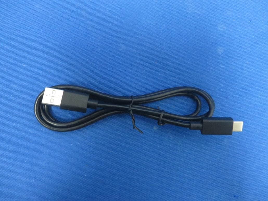
Click to zoom
Application Details
- Equipment Class
- TLD - Licensed LPAS Device
- Date of Grant
- Jun 21, 2020
- Application Purpose
- Original Equipment
- Date of Application
- Jun 07, 2020
- Equipment Note
- Digital Plug-on Transmitter
- Frequency Range
- 956.57500000 - 959.72500000
- Company
- Shure Incorporated
- Country
- United States
Documents & Files
Document Text
Text extracted from the exhibit documents filed with the FCC. Open a document above to read the original.
Users Manual
USER GUIDE Le Guide de l’Utilisateur Guia del Usuario Manual do Usuário AD3 AXIENT ® DIGITAL PLUG-ON TRANSMITTER © 2020 Shure Incorporated 27A46340 (Rev. 1) Printed in China CONSIGNES DE SÉCURITÉ IMPORTANTES 1. LIRE ces consignes. 2. CONSERVER ces consignes. 3. OBSERVER tous les avertissements. 4. SUIVRE toutes les consignes. 5. NE PAS utiliser cet appareil à proximité de l'eau. 6. NETTOYER UNIQUEMENT avec un chiffon sec. 7. NE PAS obstruer les ouvertures de ventilation. Laisser des distances suffisantes pour permettre une ventilation adéquate et effectuer l'installation en respectant les instructions du fabricant. 8. NE PAS installer à proximité d'une source de chaleur telle qu'une flamme nue, un radiateur, une bouche de chaleur, un poêle ou d'autres appareils (dont les amplificateurs) produisant de la chaleur. Ne placer aucune source à flamme nue sur le produit. 9. NE PAS détériorer la sécurité de la fiche polarisée ou de la fiche de terre. Une fiche polarisée comporte deux lames dont l'une est plus large que l'autre. Une fiche de terre comporte deux lames et une troisième broche de mise à la terre. La lame la plus large ou la troisième broche assure la sécurité de l'utilisateur. Si la fiche fournie ne s'adapte pas à la prise électrique, demander à un électricien de remplacer la prise hors normes. 10. PROTÉGER le cordon d'alimentation afin que personne ne marche dessus et que rien ne le pince, en particulier au niveau des fiches, des prises de courant et du point de sortie de l'appareil. 11. UTILISER UNIQUEMENT les accessoires spécifiés par le fabricant. 12. UTILISER uniquement avec un chariot, un pied, un trépied, un support ou une table spécifié par le fabricant ou vendu avec l'appareil. Si un chariot est utilisé, déplacer l'ensemble chariot-appareil avec précaution afin de ne pas le renverser, ce qui pourrait entraîner des blessures. 13. DÉBRANCHER l'appareil pendant les orages ou quand il ne sera pas utilisé pendant longtemps. 14. CONFIER toute réparation à du personnel qualifié. Des réparations sont nécessaires si l'appareil est endommagé d'une façon quelconque, par exemple : cordon ou prise d'alimentation endommagé, liquide renversé ou objet tombé à l'intérieur de l'appareil, exposition de l'appareil à la pluie ou à l'humidité, appareil qui ne marche pas normale- ment ou que l'on a fait tomber. 15. NE PAS exposer cet appareil aux égouttures et aux éclaboussements. NE PAS poser des objets contenant de l'eau, comme des vases, sur l'appareil. 16. La prise SECTEUR ou un coupleur d’appareil électrique doit rester facilement utilisable. 17. Le bruit aérien de l'appareil ne dépasse pas 70 dB (A). 18. L'appareil de construction de CLASSE I doit être raccordé à une prise SECTEUR dotée d'une protection par mise à la terre. 19. Pour réduire les risques d'incendie ou de choc électrique, ne pas exposer cet appareil à la pluie ou à l'humidité. 20. Ne pas essayer de modifier ce produit. Cela risque de causer des blessures et/ou la défaillance du produit. 21. Utiliser ce produit dans sa plage de températures de fonctionnement spécifiée. Ce symbole indique la présence d'une tension dangereuse dans l'appareil constituant un risque de choc électrique. Ce symbole indique que la documentation fournie avec l'appareil con- tient des instructions d'utilisation et d'entretien importantes. IMPORTANT SAFETY INSTRUCTIONS 1. READ these instructions. 2. KEEP these instructions. 3. HEED all warnings. 4. FOLLOW all instructions. 5. DO NOT use this apparatus near water. 6. CLEAN ONLY with dry cloth. 7. DO NOT block any ventilation openings. Allow sufficient distances for adequate ventila- tion and install in accordance with the manufacturer’s instructions. 8. DO NOT install near any heat sources such as open flames, radiators, heat registers, stoves, or other apparatus (including amplifiers) that produce heat. Do not place any open flame sources on the product. 9. DO NOT defeat the safety purpose of the polarized or grounding type plug. A polarized plug has two blades with one wider than the other. A grounding type plug has two blades and a third grounding prong. The wider blade or the third prong are provided for your safety. If the provided plug does not fit into your outlet, consult an electrician for replace- ment of the obsolete outlet. 10. PROTECT the power cord from being walked on or pinched, particularly at plugs, conve- nience receptacles, and the point where they exit from the apparatus. 11. ONLY USE attachments/accessories specified by the manufacturer. 12. USE only with a cart, stand, tripod, bracket, or table specified by the manu- facturer, or sold with the apparatus. When a cart is used, use caution when moving the cart/apparatus combination to avoid injury from tip-over. 13. UNPLUG this apparatus during lightning storms or when unused for long periods of time. 14. REFER all servicing to qualified service personnel. Servicing is required when the ap- paratus has been damaged in any way, such as power supply cord or plug is damaged, liquid has been spilled or objects have fallen into the apparatus, the apparatus has been exposed to rain or moisture, does not operate normally, or has been dropped. 15. DO NOT expose the apparatus to dripping and splashing. DO NOT put objects filled with liquids, such as vases, on the apparatus. 16. The MAINS plug or an appliance coupler shall remain readily operable. 17. The airborne noise of the Apparatus does not exceed 70dB (A). 18. Apparatus with CLASS I construction shall be connected to a MAINS socket outlet with a protective earthing connection. 19. To reduce the risk of fire or electric shock, do not expose this apparatus to rain or moisture. 20. Do not attempt to modify this product. Doing so could result in personal injury and/or product failure. 21. Operate this product within its specified operating temperature range. This symbol indicates that dangerous voltage constituting a risk of electric shock is present within this unit. This symbol indicates that…
Text truncated - open the document above for the full version.
Cover Letter(s)
Declaration of Authorization We Name: Shure Incorporated Address: 5800 West Touhy Avenue, Niles, IL 60714-4608, USA Declare that: Name Representative of agent: Wu Jian Agent Company name: MRT Technology (Suzhou) Co., Ltd Address: D8 Building, Youxin Industrial Park, No.2 Tian'edang Rd., Wuzhong Economic Development Zone, City: Suzhou Country China is authorized to apply for Certification of the following product(s): Product description: Digital Plug-on Transmitter Type designation: AD3 X55 Trade mark: , FCC ID: DD4AD3X55 IC: 616A-AD3X55 on our behalf. --------------------------------------------------- Signature: Craig Kozokar, EMC Project Engineer Date: 2020/06/04
Cover Letter(s)
Equipment Autorisation Division Federal Communications Commission 7435 Oakland Mills Road Columbia, MD 21046 FCC ID: DD4AD3X55 Pursuant to the provisions of Sections 0.457 and 0.459 of the Commission’s rules (47 CFR §§ 0.457, 0.459), we are requesting the Commission to withhold the following attachments as confidential document from public disclosure indefinitely. Schematic Diagram Block Diagram Operation Description Turn up procedure Above mentioned document contains detailed system and equipment description are considered as proprietary information in operation of the equipment. The public disclosure of above documents might be harmful to our company and would give competitor an unfair advantage in the market. In additional to above mentioned documents, pursuant to Public Notice DA 04-1705 of the Commission’s policy, in order to comply with the marketing regulations in 47 CFR §2.803 and the importation rules in 47 CFR §2.1204, while ensuring that business sensitive information remains confidential until the actual marketing of newly authorized devices. We are requesting the commission to grant short-term confidentiality request on the following attachments until (180 days): External Photos Internal Photos Test Setup Photos User Manual It is our understanding that all measurement test reports, FCC ID label format and correspondent during certification review process cannot be granted as confidential documents and those information will be available for p ublic review once the grant of equipment authorization is issued. Signature: Name: Craig Kozokar Title: EMC Project Engineer TEL: 847-600-8652 Email: [email protected]
Cover Letter(s)
Date: June 04, 2020 Federal Communications Commission Authorization and Evaluation Division FCC ID: DD4AD3X55 To Whom It May Concern: This letter is to ascertain that the following information of applicant, product with model(s) have been the units used for conducting FCC compliance testing, the SDoC part will be tested by FCC recognized test lab. Product: Digital Plug-on Transmitter Model: AD3 X55 If you have any question or concerns, pls. contact us. Signature: Name: Craig Kozokar Title: EMC Project Engineer TEL: 847-600-8652 Email: [email protected]
External Photos
Report No.: 2004RSU052-UE 1 of 5 EUT Photograph (1) EUT Photo (2) EUT Photo Report No.: 2004RSU052-UE 2 of 5 (3) EUT Photo (4) EUT Photo Report No.: 2004RSU052-UE 3 of 5 (5) EUT Photo (6) EUT Photo Report No.: 2004RSU052-UE 4 of 5 (7) EUT Photo (8) EUT Photo Report No.: 2004RSU052-UE 5 of 5 (9) EUT Photo
ID Label/Location Info
Label Location Label
Internal Photos
Report No.: 2004RSU052-UE 1 of 6 EUT Photograph (1) EUT Photo (2) EUT Photo Report No.: 2004RSU052-UE 2 of 6 (3) EUT Photo (4) EUT Photo Report No.: 2004RSU052-UE 3 of 6 (5) EUT Photo (6) EUT Photo Report No.: 2004RSU052-UE 4 of 6 (7) EUT Photo (8) EUT Photo Report No.: 2004RSU052-UE 5 of 6 (9) EUT Photo (10) EUT Photo Report No.: 2004RSU052-UE 6 of 6 (11) EUT Photo (12) EUT Photo
RF Exposure Info
MRT Technology (Suzhou) Co., Ltd Report No.: 2004RSU052-U6 Phone: +86-512-66308358 Report Version: V02 Web: www.mrt-cert.com Issue Date: 06-16-2020 Page Number: 1 of 51 FCC ID: DD4AD3X55 Applicant: Shure Incorporated Application Type: Certification Product: Digital Plug-on Transmitter Model No.: AD3 X55 Brand Name: , FCC Classification: Licensed LPAS Device (TLD) FCC Rule Part(s): FCC 47 CFR Part 2.1093 Test Procedure(s): IEEE 1528:2013, IEEE C95.1- 2005, KDB 447498 D01v06, KDB 865664 D01v01r04 Test Date: May 14 ~ June 16, 2020 SAR MEASUREMENT REPORT Reviewed By: ( Jame Yuan ) Approved By: ( Robin Wu ) The test results relate only to the samples tested. This equipment has been shown to be capable of compliance with the applicable technical standards as indicated in the measurement report and was tested in accordance with the measurement procedures specified in IEEE1528, KDB 447498 and KDB 865664. Test results reported herein relate only to the item(s) tested. The test report shall not be reproduced except in full without the written approval of MRT Technology (Suzhou) Co., Ltd. Report No.: 2004RSU052-U6 Page Number: 2 of 51 Revision History Report No. Version Description Issue Date Note 2004RSU052-U6 Rev. 01 Initial Report 05-25-2020 Invalid 2004RSU052-U6 Rev. 02 Update some test data 06-16-2020 Valid Report No.: 2004RSU052-U6 Page Number: 3 of 51 CONTENTS Description Page 1. Introduction ............................................................................................................................ 6 1.1. Scope ........................................................................................................................... 6 1.2. MRT Test Location ....................................................................................................... 6 2. Product Information ............................................................................................................... 7 2.1. General Description for EUT ......................................................................................... 7 2.2. Product Specification Subjective to this Report ............................................................. 7 2.3. Ancillary Equipment ...................................................................................................... 7 3. Summary of Test Result ........................................................................................................ 8 3.1. Test Standards ............................................................................................................. 8 3.2. Environment Condition ................................................................................................. 8 3.3. RF Exposure Limits ...................................................................................................... 8 3.4. Test Result Summary ................................................................................................... 9 4. Specific Absorption Rate (SAR).......................................................................................... 10 4.1. Introduction ................................................................................................................. 10 4.2. Definition .................................................................................................................... 10 5. DASY6 Measurement System ............................................................................................. 11 5.1. Introduction ................................................................................................................. 11 5.2. DASY6 Measurement System Diagram ...................................................................... 11 5.3. System Components Details ....................................................................................... 12 6. The SAR Measurement Procedure ..................................................................................... 23 6.1. Measurement Process Diagram.................................................................................. 23 6.2. Test Position Definition ............................................................................................... 24 6.3. Test Procedure ........................................................................................................... 27 7. System Verificaiton.............................................................................................................. 29 7.1. Tissue Check .............................................................................................................. 29 7.2. System Check ............................................................................................................ 32 8. Analysis and Results ........................................................................................................... 34 8.1. Antenna Location ........................................................................................................ 34 8.2. Conducted Power ....................................................................................................... 35 8.3. SAR Exclusion Analysis .............................................................................................. 37 8.4. Required Configurations of SAR Test ......................................................................... 39 Report No.: 2004RSU052-U6 Page Number: 4 of 51 8.5. SAR Test Results ....................................................................................................... 40 8.6. Estimated SAR Calculation ......................................................................................... 41 9. Simultaneous Transmission Analysis ................................................................................ 42 10. Test Equipment Used .......................................................................................................... 43 11. Measurement Uncertainty ...........................…
Text truncated - open the document above for the full version.
RF Exposure Info
D900V2,Serial No.1d109Extended Dipole Calibrations Per IEEE Std 1528-2013,the dipole should have a return loss better than -20dB at the test frequency to reduce uncertainty in the power measurement. Per KDB 865664 D01,if dipoles are verified in return loss(<-20dB,within 20% of prior calibration),and in impedance (within 5 ohm of prior calibration),the annual calibration is not necessary and the calibration interval can be extended. Justification of the extended calibration D900V2 Serial No.1d109 900 Head Date of Measurement Return-Loss (dB) Delta (%) Real Impedance (ohm) Delta (ohm) Imaginary Impedance (ohm) Delta (ohm) 10.29.2018 -25.3 -- 49.099 -- -5.2893 -- 10.09.2019 -25.090 0.83 49.592 0.493 -5.5364 0.2471 D900V2 Serial No.1d109 900 Body Date of Measurement Return-Loss (dB) Delta (%) Real Impedance (ohm) Delta (ohm) Imaginary Impedance (ohm) Delta (ohm) 10.29.2018 -20 -- 45.054 -- -8.1459 -- 10.09.2019 -21.069 5.07 46.095 1.041 -7.5753 0.5706 The return loss is < -20dB, within 20% of prior calibration; the impedance is within 5 ohm of prior calibration. Therefore the verification result should support extended calibration. Dipole Verification Data D900V2 Serial No.1d109 900MHz-Head 900MHz - Body
Test Report
MRT Technology (Suzhou) Co., Ltd Report No.: 2004RSU052-U5 Phone: +86-512-66308358 Report Version: V01 Web: www.mrt-cert.com Issue Date: 05-27-2020 Page Number: 1 of 80 FCC ID: DD4AD3X55 APPLICANT: Shure Incorporated Application Type: Certification Product: Digital Plug-on Transmitter Model No.: AD3 X55 Brand Name: , FCC Classification: Licensed LPAS Device (TLD) FCC Rule Part(s): Part 74 Subpart H (Section 74.861) Test Procedure(s): ANSI C63.26-2015, KDB 206256 D01v02 ETSI EN 300 422-1 V1.4.2 (2011-08) Test Date: April 24 ~ May 26, 2020 MEASUREMENT REPORT FCC PART 74 Subpart H Reviewed By: ( Jame Yuan ) Approved By: (Robin Wu) The test results relate only to the samples tested. The test results shown in the test report are traceable to the national/international standards through the calibration of the equipment and evaluated measurement uncertainty herein. The test report shall not be reproduced except in full without the written approval of MRT Technology (Suzhou) Co., Ltd. Report No.: 2004RSU052-U5 Page Number: 2 of 80 Revision History Report No. Version Description Issue Date Note 2004RSU052-U5 Rev. 01 Initial Report 05-27-2020 Valid Report No.: 2004RSU052-U5 Page Number: 3 of 80 CONTENTS Description Page 1. INTRODUCTION ..................................................................................................................... 6 1.1. Scope ........................................................................................................................... 6 1.2. MRT Test Location ....................................................................................................... 6 2. PRODUCT INFORMATION ..................................................................................................... 7 2.1. Equipment Description .................................................................................................. 7 2.2. Product Specification Subjective to this Report ............................................................. 7 2.3. Working Frequencies for this report .............................................................................. 7 2.4. Test Software ............................................................................................................... 8 2.5. EMI Suppression Device(s) / Modifications ................................................................... 8 2.6. Labeling Requirements ................................................................................................. 8 3. DESCRIPTION OF TEST ........................................................................................................ 9 3.1. Evaluation Procedure ................................................................................................... 9 3.2. Radiated Measurement................................................................................................. 9 4. TEST EQUIPMENT CALIBRATION DATE .............................................................................11 5. MEASUREMENT UNCERTAINTY ......................................................................................... 13 6. TEST RESULT ...................................................................................................................... 14 6.1. Summary .................................................................................................................... 14 6.2. RF Output Power Measurement ................................................................................. 15 6.2.1. Test Limit .................................................................................................................... 15 6.2.2. Test Procedure Used .................................................................................................. 15 6.2.3. Test Setting ................................................................................................................. 15 6.2.4. Test Setup................................................................................................................... 15 6.2.5. Test Result .................................................................................................................. 16 6.3. Frequency Tolerance Measurement ........................................................................... 17 6.3.1. Test Limit .................................................................................................................... 17 6.3.2. Test Procedure ........................................................................................................... 17 6.3.3. Test Setting ................................................................................................................. 17 6.3.4. Test Setup................................................................................................................... 18 6.3.5. Test Result .................................................................................................................. 19 6.4. 99% Occupied Bandwidth Measurement .................................................................... 22 6.4.1. Test Limit .................................................................................................................... 22 6.4.2. Test Procedure used ................................................................................................... 22 6.4.3. Test Setting ................................................................................................................. 22 6.4.4. Test Setup................................................................................................................... 22 Report No.: 2004RSU052-U5 Page Number: 4 of 80 6.4.5. Test Result .................................................................................................................. 23 6.5. Out-of-band Emission Mask Measurement ................................................................. 28 6.5.1. Test Limit ..................................................…
Text truncated - open the document above for the full version.
Test Report
Report No.: 2004RSU052-U5 Page Number: 39 of 80 Emission Mask - HD Mode, 2mW Channel 941.625MHz Reference Level Emission Mask Channel 946.750 MHz Reference Level Emission Mask Channel 951.875MHz Reference Level Emission Mask Report No.: 2004RSU052-U5 Page Number: 40 of 80 Emission Mask - HD Mode, 2mW Channel 952.975MHz Reference Level Emission Mask Channel 956.125MHz Reference Level Emission Mask Report No.: 2004RSU052-U5 Page Number: 41 of 80 Emission Mask - HD Mode, 2mW Channel 956.575MHz Reference Level Emission Mask Channel 959.725MHz Reference Level Emission Mask Report No.: 2004RSU052-U5 Page Number: 42 of 80 6.6. Necessary Bandwidth Measurement 6.6.1.Test Limit Digital emissions within the band from one megahertz below to one megahertz above the carrier frequency shall comply with the emission mask in section 8.3.2.2 of the European Telecommunications Institute Standard ETSI EN 300 422-1 v1.4.2, the transmitter output spectrum shall be within the mask defined as below figure. 6.6.2.Test Procedure Used EN 300 422-1 V1.4.2 clause 8.3.2.1. 6.6.3.Test Setting The EUT was powered up and the transmit frequency & power output of the EUT were selected. The spectrum analyzer center frequency is set to the nominal EUT channel center frequency. Only lowest and highest channel 470.125 and 514.000 MHz is required, at an output power level of 1mW and 10mW. Report No.: 2004RSU052-U5 Page Number: 43 of 80 6.6.4.Test Setup Report No.: 2004RSU052-U5 Page Number: 44 of 80 6.6.5.Test Result Test Site TR3 Temperature 25°C Test Engineer Eric Xu Relative Humidity 52% Model No. AD3 X55 Test Date 2020/05/06 ~ 2020/05/11 Necessary Bandwidth - STD Mode, 2mW, 941.625MHz Step 1 Step 2 Step 3 Report No.: 2004RSU052-U5 Page Number: 45 of 80 Necessary Bandwidth - STD Mode, 2mW, 946.750MHz Step 1 Step 2 Step 3 Report No.: 2004RSU052-U5 Page Number: 46 of 80 Necessary Bandwidth - STD Mode, 2mW, 951.875 MHz Step 1 Step 2 Step 3 Report No.: 2004RSU052-U5 Page Number: 47 of 80 Necessary Bandwidth - STD Mode, 2mW, 952.975MHz Step 1 Step 2 Step 3 Report No.: 2004RSU052-U5 Page Number: 48 of 80 Necessary Bandwidth - STD Mode, 2mW, 956.125MHz Step 1 Step 2 Step 3 Report No.: 2004RSU052-U5 Page Number: 49 of 80 Necessary Bandwidth - STD Mode, 2mW, 956.575MHz Step 1 Step 2 Step 3 Report No.: 2004RSU052-U5 Page Number: 50 of 80 Necessary Bandwidth - STD Mode, 2mW, 959.725MHz Step 1 Step 2 Step 3 Report No.: 2004RSU052-U5 Page Number: 51 of 80 Necessary Bandwidth - STD Mode, 10mW, 941.625MHz Step 1 Step 2 Step 3 Report No.: 2004RSU052-U5 Page Number: 52 of 80 Necessary Bandwidth - STD Mode, 10mW, 946.750MHz Step 1 Step 2 Step 3 Report No.: 2004RSU052-U5 Page Number: 53 of 80 Necessary Bandwidth - STD Mode, 10mW, 951.875 MHz Step 1 Step 2 Step 3 Report No.: 2004RSU052-U5 Page Number: 54 of 80 Necessary Bandwidth - STD Mode, 10mW, 952.975MHz Step 1 Step 2 Step 3 Report No.: 2004RSU052-U5 Page Number: 55 of 80 Necessary Bandwidth - STD Mode, 10mW, 956.125MHz Step 1 Step 2 Step 3 Report No.: 2004RSU052-U5 Page Number: 56 of 80 Necessary Bandwidth - STD Mode, 10mW, 956.575MHz Step 1 Step 2 Step 3 Report No.: 2004RSU052-U5 Page Number: 57 of 80 Necessary Bandwidth - STD Mode, 10mW, 959.725MHz Step 1 Step 2 Step 3 Report No.: 2004RSU052-U5 Page Number: 58 of 80 Necessary Bandwidth - STD Mode, 35mW, 941.625MHz Step 1 Step 2 Step 3 Report No.: 2004RSU052-U5 Page Number: 59 of 80 Necessary Bandwidth - STD Mode, 35mW, 946.750MHz Step 1 Step 2 Step 3
Test Report
Report No.: 2004RSU052-U5 Page Number: 60 of 80 Necessary Bandwidth - STD Mode, 35mW, 951.875 MHz Step 1 Step 2 Step 3 Report No.: 2004RSU052-U5 Page Number: 61 of 80 Necessary Bandwidth - STD Mode, 35mW, 952.975MHz Step 1 Step 2 Step 3 Report No.: 2004RSU052-U5 Page Number: 62 of 80 Necessary Bandwidth - STD Mode, 35mW, 956.125MHz Step 1 Step 2 Step 3 Report No.: 2004RSU052-U5 Page Number: 63 of 80 Necessary Bandwidth - STD Mode, 35mW, 956.575MHz Step 1 Step 2 Step 3 Report No.: 2004RSU052-U5 Page Number: 64 of 80 Necessary Bandwidth - STD Mode, 35mW, 959.725MHz Step 1 Step 2 Step 3 Report No.: 2004RSU052-U5 Page Number: 65 of 80 Necessary Bandwidth - HD Mode, 2mW, 941.625MHz Step 1 Step 2 Step 3 Report No.: 2004RSU052-U5 Page Number: 66 of 80 Necessary Bandwidth - HD Mode, 2mW, 946.750MHz Step 1 Step 2 Step 3 Report No.: 2004RSU052-U5 Page Number: 67 of 80 Necessary Bandwidth - HD Mode, 2mW, 951.875 MHz Step 1 Step 2 Step 3 Report No.: 2004RSU052-U5 Page Number: 68 of 80 Necessary Bandwidth - HD Mode, 2mW, 952.975MHz Step 1 Step 2 Step 3 Report No.: 2004RSU052-U5 Page Number: 69 of 80 Necessary Bandwidth - HD Mode, 2mW, 956.125MHz Step 1 Step 2 Step 3 Report No.: 2004RSU052-U5 Page Number: 70 of 80 Necessary Bandwidth - HD Mode, 2mW, 956.575MHz Step 1 Step 2 Step 3 Report No.: 2004RSU052-U5 Page Number: 71 of 80 Necessary Bandwidth - HD Mode, 2mW, 959.725MHz Step 1 Step 2 Step 3 Report No.: 2004RSU052-U5 Page Number: 72 of 80 6.7. Radiated Spurious Emissions Measurement 6.7.1.Test Limit According to FCC Part 74.861(e)(7), beyond one megahertz below and above the carrier frequency, emissions shall comply with the limits specified in section 8.4 of ETSI EN 300 422-1 v1.4.2. State Frequency Range 47MHz to 74MHz, 87.5MHz to 137MHz 174MHz to 230MHz, 470MHz to 862MHz Other Frequencies below 1000MHz Frequencies above 1000MHz Operation 4nW 250nW 1uW Standby 2nW 2nW 20nW 6.7.2.Test Procedure Used ETSI EN 300 422-1 V1.4.2 clause 8.4.2. 6.7.3.Test Setting Table 1 - RBW as a function of frequency Frequency RBW 25 ~ 30 MHz 9 kHz 30 ~ 1000 MHz 100 kHz 1000 ~ 6000 MHz 1 MHz Emissions shall be investigated up to the 10 th harmonic of the fundamental. Compliance with the emission limits shall be demonstrated using a RMS Average detector. All significant broadband and narrowband signals found in the preliminary sweeps were measured using a peak detector at a test distance of 3 meters. At each frequency at which a component is detected, the sample shall be rotated to obtain maximum response and the effective radiated power of that component determined by a substitution measurement. Report No.: 2004RSU052-U5 Page Number: 73 of 80 6.7.4.Test Setup Below 1GHz Test Setup: Above 1GHz Test Setup: Report No.: 2004RSU052-U5 Page Number: 74 of 80 6.7.5.Test Result Test Site AC1 Temperature 25°C Test Engineer Buter Shi Relative Humidity 54% Test Mode STD Mode, 35mW Test Date 2020/05/16 Test Channel (MHz) Frequency (MHz) Ant. Pol. (H/V) SG Reading (dBm) Cable Loss (dB) Substitute Antenna Gain (dBi) EIRP (dBm) Limit (dBm) Margin (dB) 941.625 2824.9 H -66.3 0.7 11.1 -55.9 -30.0 -25.9 3766.5 H -67.1 0.8 12.3 -55.6 -30.0 -25.6 7533.0 H -57.7 1.2 11.6 -47.3 -30.0 -17.3 2824.9 V -63.9 0.7 11.1 -53.5 -30.0 -23.5 3766.5 V -65.1 0.8 12.3 -53.6 -30.0 -23.6 7533.0 V -56.4 1.2 11.6 -46.0 -30.0 -16.0 946.750 2480.3 H -67.5 0.6 10.7 -57.5 -30.0 -27.5 3787.0 H -67.0 0.8 12.3 -55.5 -30.0 -25.5 7574.0 H -60.0 1.1 11.7 -49.4 -30.0 -19.4 2480.3 V -66.4 0.6 10.7 -56.4 -30.0 -26.4 3787.0 V -66.7 0.8 12.3 -55.2 -30.0 -25.2 7574.0 V -57.9 1.1 11.7 -47.3 -30.0 -17.3 951.875 2855.6 H -67.7 0.7 11.1 -57.3 -30.0 -27.3 3807.5 H -67.9 0.8 12.3 -56.4 -30.0 -26.4 7663.0 H -59.5 1.1 12.0 -48.6 -30.0 -18.6 2855…
Text truncated - open the document above for the full version.
Contact Information
Applicant
Craig Kozokar(EMC Project Engineer)
Technical Contact
MRT Technology (Suzhou) Co., LtdRobin Wu
[email protected]86-512-66308358
D8 Building, Youxin Industrial Park, · Suzhou · China
Non-Technical Contact
MRT Technology (Suzhou) Co., LtdRobin Wu
[email protected]86-512-66308358
Test Firm
MRT Technology (Suzhou) Co., Ltd.Mr. Marlin Chen
[email protected]+86-512-66308358
Technical Specifications
| # | Rule Parts | Frequency Range | Power Output | Emission | Tolerance |
|---|---|---|---|---|---|
| 3 | 74H | 956.575 MHz - 959.725 MHz | 25.90 mW | 181KF1E | 0.09 ppm |
Other Applications from Shure Incorporated
DD4IMXBP
Dec 24, 2025UC Wall
Equipment Class
NII - Unlicensed National Information Infrastructure TXDD4SLXD3EG57
Jul 25, 2025Plug-on Wireless Transmitter
Equipment Class
DTS - Digital Transmission System
DD4ULXD8G50
Sep 18, 2024Wireless Gooseneck Transmitter
Equipment Class
DWM - Part 15 Wireless Microphone
DD4ULXD8H50
Sep 18, 2024Wireless Gooseneck Transmitter
Equipment Class
DWM - Part 15 Wireless Microphone
DD4ULXD6G50
Sep 08, 2024Wireless Boundary Transmitter
Equipment Class
TLD - Licensed LPAS Device