DD4BLX1DWireless Microphone Transmitter
Shure Incorporated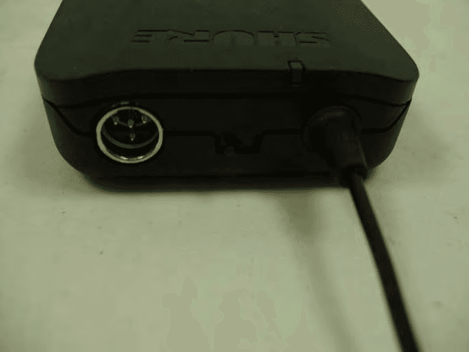
Click to zoom
Application Details
- Equipment Class
- TNT - Licensed Non-Broadcast Transmitter Worn on Body
- Date of Grant
- May 31, 2012
- Application Purpose
- Original Equipment
- Date of Application
- May 31, 2012
- Equipment Note
- Wireless Microphone Transmitter
- Frequency Range
- 614.00000000 - 638.00000000
- Company
- Shure Incorporated
- Country
- United States
Documents & Files
Document Text
Text extracted from the exhibit documents filed with the FCC. Open a document above to read the original.
Users Manual
audio ready group (A-Y) channel (0-9) power BLX88 audio ready group (A-Y) channel (0-9) audio ready group (A-Y) channel (0-9) power BLX4 channel group -10 dB group (A-Y) channel (0-9) ©2012 Shure Incorporated 27A16035 (Rev. 2) BLX Wireless System 1 BLX System Components Note: Your system comes with a combination of the fol- lowing components. • BLX1 Bodypack Transmitter • BLX2 Handheld Transmitter (choice of SM58, BETA58A, or PG58) • BLX4 Wireless Receiver • BLX88 Dual Wireless Receiver • PS21 Power Supply • Lavalier microphone (choice of PG185, WL185 or WL93) • Headworn microphone (choice of PG30 or WH30-TQG) • Instrument microphone (BETA98H) • Guitar cable (WA302) Front Panel Features BLX88 ① audio LED Indicates strength of incoming audio signal: green for normal and red for overload. ② Ready LED Icon Green light indicates system is ready for use and receiving transmitter signal. ③ LED Display Displays group and channel setting. ④ group and channel Buttons Scan: Push and release group button to scan for an open group and channel. Manual: Push and hold group button to find an open group. Push and release channel button to find a channel in the current group. ⑤ power Button Turns power on or off. BLX4 audio ready group (A-Y) channel (0-9) power BLX88 audio ready group (A-Y) channel (0-9) audio ready group (A-Y) channel (0-9) power BLX4 ⑤ ①② ③ ④ ① ② ③ ④ ⑤ ① ② ③ ④ 2 BLX2 ① LED Indicator Displays power and battery status (see table). ② power Button Push to turn power on or off. ③ group Button Changes group setting. ④ channel Button Changes channel and gain setting. ⑤ LED Display Displays group and channel setting. ⑥ Identification Cap ⑦ Battery Compartment ① AC Adapter Jack ② Adapter Cord Tie-Off ③ XLR microphone output jack MIC out ④ 6.35 mm (1/4") instrument level output jack instrument out Note: XLR and 1/4" connectors can be used simultane- ously. Refer to the output information in Specifications. BLX1 ① LED Indicator Displays power and battery status (see table). ② power Switch Toggles power on or off. ③ Audio Gain Adjustment Gain thumb wheel—located on the inside of bodypack door. ④ 4-Pin Microphone Input Jack (TA4 connector) ⑤ group Button Changes group setting. ⑥ channel Button Changes channel setting. ⑦ LED Display Displays group and channel setting. ⑧ Antenna ⑨ Battery Compartment Back Panel BLX4 BLX88 BLX1 BLX2 channel group -10 dB group (A-Y) channel (0-9) ① ② ④ ⑤ ⑥ ⑦ ⑧ ⑨ ③ ③ ④ ⑥ ⑦ ⑤ ① ② POWER MIC OUT INSTRUMENT OUT 12-18 V 160 mA ① ② ③ ④ ① ② ③ ③ ④ ④ POWER MIC OUT INSTRUMENT OUT 12-18 V 160 mA INSTRUMENT OUT MIC OUT 3 Transmitter LED Indicators LED IndicatorStatus GreenReady Rapidly Flashing AmberControls locked Solid RedBattery power low (1 hour remaining*) Flashing Red and shuts offBatteries dead (change batteries to power on transmitter) *For alkaline batteries only. For rechargeable batteries, solid red means the batteries are dead. Before you begin, turn off all transmitters and turn on any equipment (other microphones or personal monitoring systems) that could cause interference during the performance. 1. Press and release the group button on the receiver. The receiver scans for the clearest group and proceeds to channel scan. Note: If you want to stop the scan, push the group or channel button. 2. Turn on transmitter and change the group and channel to match the receiver (See Manually Setting Group and Channel). Once the receiver is set up, perform an audio check on the microphone. Manually Setting Group and Channel Single System Setup Receiver Setup Group (letter) 1. Hold the group button on the receiver until the display begins to flash. 2. While the display is flashing, press the group button again to advance to the next group. Note: Only the group setting will be dis- played during the manual setup. 3. Once the desired group is reached, release the group button. Then the receiver will au- tomatically perform a channel scan. Channel (number) If channel needs to be changed, follow the same procedure using the channel button instead of the group button. groupchannel channel group group channel channel channel group group channel group group channel channel channel group group 4 Transmitter Setup Transmitter group and channel must be manually set to match the receiver. Group (letter) 1. Press and release the group button on the transmitter to activate the display. Press the group button again and the display flashes. 2. While the display is flashing, press the group button again to advance to the desired group setting. Channel (number) If channel needs to be changed, follow the same procedure using the channel button instead of the group button. Note: When the group and channel correctly match the receiver, the ready LED on receiver illuminates. Multiple System Setup Up to 12 systems can operate simultaneously (band and RF environment dependent). Important: Set up each system one-at-a-time. Once a receiver and transmitter is tuned to the same group and channel, leave the transmitter powered on. Otherwise, scans from the other receivers will not detect that channel as occupied. For the BLX88, be sure to setup both transmitters before progressing to the next receiver. Turn on any other equipment that could cause interference during the performance so it will be detected during the group and channel scans in the following steps. Before you begin system set up, turn all receivers ON and all transmitters OFF. For the first receiver: 1. Perform a group scan. This finds the group with the most clear channels. Note: For the BLX88, the group scan sets up both receivers at the same time. 2. Turn on the first transmitter and change the group and channel to match receiver. 3. Leave the transmitter on and continue with the additional systems. For each additional receiver: 1. Use manual setup to change the receiver to match the group setting of the first receiver. Recall that each time the group setting is changed, a channel scan is automatically done. 2. Turn on the transmitter and ch…
Text truncated - open the document above for the full version.
Cover Letter(s)
May 15, 2012 Elite Electronic Engineering, Inc. 1516 Centre Circle Downers Grove, Illinois 60515-1082 SUBJECT: REQUEST FOR NON-DISCLOSURE FOR FCC ID: DD4BLX1D To Whom It May Concern: Pursuant to 47 CFR Section 0.459, Shure Incorporated hereby requests non-disclosure and confidential treatment of the following materials submitted in support of FCC certification application for FCC ID # DD4BLX1D: a. Schematic Diagrams b. Operational Description c. Block Diagram d. Parts List e. Tune Up Procedure Above materials contain trade secrets, proprietary and technical information which would customarily be guarded from competitors under 47 CFR section 0.457(d)(2). Disclosure or publication of any portion of this company confidential material to other parties could cause substantial competitive harm and provide unjustified benefits for competitors. Shure Incorporated understands that pursuant to 47 CFR section 0.457(d)(1)(ii) disclosure of the applicant and all accompanying documentation will not be made before the date of the grant. Sincerely yours, Craig Kozokar EMC Project Engineer, Global Compliance Shure Incorporated
External Photos
Shure BLX1 External Photographs Shure BLX1 Front View Shure BLX1 Rear View Shure BLX1 Left Side View Shure BLX1 Right Side View Shure BLX1 Top View Shure BLX1 Bottom View Shure BLX1 Front View – Battery Door Open
ID Label/Location Info
Shure BLX1 Label Location Shure BLX1 Back View
Internal Photos
Shure BLX1 Internal Photographs BLX1 PCB Top BLX1 PCB Back
Test Setup Photos
Engineering Test Report No. 1003062-01A Page 15 of 118 Test Setup for Radiated Emissions, Above 1GHz – Horizontal Polarization Test Setup for Radiated Emissions, Above 1GHz – Vertical Polarization
Contact Information
Applicant
Craig Kozokar(EMC Project Engineer)
Technical Specifications
| # | Rule Parts | Frequency Range | Power Output | Emission | Tolerance |
|---|---|---|---|---|---|
| 1 | 74 | 614 MHz - 638 MHz | 8.84 mW | 150KF3E | 10.0000000000 ppm |
Other Applications from Shure Incorporated
DD4IMXBP
Dec 24, 2025UC Wall
Equipment Class
NII - Unlicensed National Information Infrastructure TXDD4SLXD3EG57
Jul 25, 2025Plug-on Wireless Transmitter
Equipment Class
DTS - Digital Transmission System
DD4ULXD8G50
Sep 18, 2024Wireless Gooseneck Transmitter
Equipment Class
DWM - Part 15 Wireless Microphone
DD4ULXD8H50
Sep 18, 2024Wireless Gooseneck Transmitter
Equipment Class
DWM - Part 15 Wireless Microphone
DD4ULXD6G50
Sep 08, 2024Wireless Boundary Transmitter
Equipment Class
TLD - Licensed LPAS Device