DD4FP3CWireless Microphone Transmitter
Shure Incorporated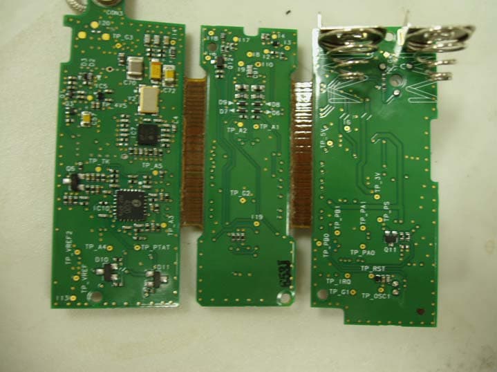
Click to zoom
Application Details
- Equipment Class
- TNF - Licensed Non-Broadcast Transmitter Held to Face
- Date of Grant
- Mar 01, 2012
- Application Purpose
- Original Equipment
- Date of Application
- Mar 01, 2012
- Equipment Note
- Wireless Microphone Transmitter
- Frequency Range
- 638.00000000 - 662.00000000
- Company
- Shure Incorporated
- Country
- United States
Documents & Files
Document Text
Text extracted from the exhibit documents filed with the FCC. Open a document above to read the original.
Users Manual
1 FP Wireless System Features • Audio Reference Companding for crystal-clear audio • Automatic Frequency Selection locates an open frequency at the touch of a button • Automatic Transmitter Setup instantly syncs the transmitter to the receiver frequency • Up to 12 compatible systems simultaneously • All components powered by 2 AA batteries – no power cord required • Transmitter gain attenuation control manages input level FP1 Bodypack Transmitter Lightweight, durable hous- ing; for use with TA4F- connection microphones including lavaliers and headsets FP2 Handheld Transmitter Lightweight, durable housing; available with either the legendary Shure SM58 ® cardioid dynamic wireless cap- sule or with the VP68 condenser omnidirec- tional capsule; compat- ible with all Shure wire- less capsules FP3 Plug-On Transmitter Durable metal housing, ergonomically designed for comfortable grip; XLR connectivity allows for use with any wired dynamic XLR microphone FP5 Portable Receiver Lightweight, durable housing, suitable for mounting on camera or person, diversity anten- nas, output via TA3F cable to either XLR or 1/8” connectors. Featuring a comprehensive selection of system configurations with key wireless audio technologies and components, FP Wireless provides the ability to cap- ture crystal-clear audio with confidence. With simple and flexible components, including a portable receiver and XLR plug-on transmitter, it has never been easier for audio to be captured in the demanding and dynamic videography and electronic field production (EFP) environments. Furnished Accessories Micrphone Clip (FP2)Plug-on Transmitter Belt Clip and Protective Skin (FP3) Camera Shoe Mount (FP5)TA3F-to-XLRm Audio Cable TA3F-to-3.5mm Dual-mono Audio Cable FP1 - FP5 FP3FP2 FP1 2 Quickstart Install Batteries Power up the FP5 ReceiverGroup scan for open frequenciesPower up the transmitter Sync transmitter and receiver FP5 3 12 3 PGX1 4 5 PGXD 1 2 12 5 3 6 FP1 FP2 FP3 3 FP5 Receiver ① Power LED Green Power on Yellow Low battery alert Red Critical low battery, replace immediately Flashing red on power up Battery dead ② RF LED Illuminates when successfully synced to a transmitter (or manually tuned to a transmitter's frequency) ③ Power Button Press and hold to power on or off. ④ Infrared (IR) port Sends infrared beam to synchronize frequencies. ⑤ TA3M Jack Use with TA3F cable for audio out. ⑥ Audio Output Gain Adjust audio output level to devices such as cameras or recorders. ⑦ LCD Screen Displays current settings for GROUP and CHANNEL and battery life. ⑧ Scan Button Group scan: Push and hold (3 sec.) to find an open group and channel. Channel scan: Push and release to find an open channel in the current group. ⑨ Sync button Align receiver and transmitter and press sync. Blue IR LED indicates successful sync. Note: Press sync and scan buttons to manually enter group and chan- nel numbers ⑩ Antennas Two antennas for diversity reception. Transmitter Controls and Connectors ① Indicator LED Green Ready Flashing green Controls locked Flashing red IR transmission in progress Solid red Battery power low Flashing red on startup Batteries dead (transmitter cannot be turned on until batteries are changed) Rapic flashing red after synchronization Transmitter and receive incompatible; contact your Shure reseller ② Power Button Press and hold to power on or off. ③ Infrared (IR) Port Receives infrared beam to synchronize frequencies. When using multiple systems, only one transmitter IR port should be exposed at a time. ④ 4-Pin Microphone Input Jack Use with with a TA4F connector for a lavalier or headset microphone. ⑤ Audio Input Gain Adjusts audio level. ⑥ XLR Connection (FP3 only) Plug into an XLR microphone or the output of an audio device. ⑦ Audio Input Level Indicator (FP3 only) Red Signal clip Yellow Nominal peak Green Audio present 7 PGXD BIAS AUDIO 0dB -10dB AUDIO 0dB -10dB FP2 FP1 FP3 0 -10dB mic 0 -10dB mic 4 Adjusting Gain FP1 and FP3 Perform a sound check. Use the audio gain control located on the side (FP1) or front (FP3) of the unit to adjust the gain up (+) or down (−) until desired level is reached. FP3 only: Adjust so the audio input level indicator flickers yellow at peak sound levels. FP2 The handheld transmitter normally does not require adjustment and should be left at 0dB for most appli- cations. Only use the –10dB setting for loud singing or other high SPL applica- tions if there is noticable distortion. Access the gain adjustment switch by unscrewing the head of the microphone. Use the tip of a pen or a small screwdriver to move the switch: 0dB: For normal use. –10dB: Use only if audio distorts due to high SPL levels. Single System Setup 1. Perform a group scan: Press and hold the scan button for 3 seconds. After the scan com- pletes, the new group and channel is automatically activated and saved. 2. Synchronize the transmitter: Align the transmitter and receiver infrared (IR) ports and press the sync button. After a successful sync, the transmitter LED momentarily flashes and the blue RF LED illuminates. Multiple System Setup Use the following steps to ensure the best performance when using mul- tiple wireless systems at the same location. 1. Turn all receivers on and all transmitters off. Note: Turn on any other digital equipment that could cause interfer- ence during the performance so it will be detected during the frequen- cy scans in the following steps. 2. Perform a group scan using the first receiver by pressing and holding the scan button for 3 seconds. 3. Turn on the first transmitter and sync it to the receiver. For each additional system: 1. Manually set the group number to match the first receiver (see Manual Group and Channel Selection). 2. Perform a channel scan by pressing the scan button. 3. Sync the transmitter to the receiver. Important: After syncing each transmitter, leave it on so that scans from the other receivers do not select that channel. Be sure only one transmit- ter IR port is exposed w…
Text truncated - open the document above for the full version.
Cover Letter(s)
February 10, 2012 Elite Electronic Engineering, Inc. 1516 Centre Circle Downers Grove, Illinois 60515-1082 SUBJECT: REQUEST FOR NON-DISCLOSURE FOR FCC ID: DD4FP3C To Whom It May Concern: Pursuant to 47 CFR Section 0.459, Shure Incorporated hereby requests non-disclosure and confidential treatment of the following materials submitted in support of FCC certification application for FCC ID # DD4FP3C: a. Schematic Diagrams b. Operational Description c. Block Diagram d. Parts List e. Tune Up Procedure Above materials contain trade secrets, proprietary and technical information which would customarily be guarded from competitors under 47 CFR section 0.457(d)(2). Disclosure or publication of any portion of this company confidential material to other parties could cause substantial competitive harm and provide unjustified benefits for competitors. Shure Incorporated understands that pursuant to 47 CFR section 0.457(d)(1)(ii) disclosure of the applicant and all accompanying documentation will not be made before the date of the grant. Sincerely yours, Craig Kozokar EMC Project Engineer, Global Compliance Shure Incorporated
Internal Photos
Shure FP3 Internal Photographs FP3 PCB Top FP3 PCB Back
Test Report
Engineering Test Report No. 1102377-01 Electromagnetic Compatibility Tests on a VIVA FP3 Adaptor Transmitter, Part No. FP3 For : Shure Inc. 5800 West Touhy Avenue Niles, IL 60714 P.O. No. : 4500211799; 211798 Dates Tested : December 7, 2011 through February 8, 2012 Test Personnel : Craig M. Dinsmore, Specification : FCC "Code of Federal Regulations” Title 47 Part 74 Industry Canada RSS-123 Test Report By : Craig M. Dinsmore Sr. EMC Engineer Approved By : Raymond J. Klouda Registered Professional Engineer of Illinois - 44894 Elite Electronic Engineering Inc. 1516 Centre Circle Downers Grove, IL 60515 Tel : (630) 495-9770 Fax: (630) 495-9785 www.elitetest.com Engineering Test Report No. 1102377-01 THIS REPORT SHALL NOT BE REPRODUCED, EXCEPT IN FULL, WITHOUT THE WRITTEN APPROVAL OF ELITE ELECTRONIC ENGINEERING INCORPORATED. Page 2 of 143 TABLE OF CONTENTS PARAGRAPH DESCRIPTION OF CONTENTS PAGE NO. 1. Introduction ........................................................................................................................................................ 5 1.1 Scope of Tests .......................................................................................................................................... 5 1.2 Purpose .................................................................................................................................................... 5 1.3 Deviations, Additions, and Exclusions ...................................................................................................... 5 1.4 EMC Laboratory Identification .................................................................................................................. 5 1.5 Laboratory Conditions .............................................................................................................................. 5 2. Applicable Documents ....................................................................................................................................... 5 3. Test Item Setup and Operation ......................................................................................................................... 6 3.1 General Description .................................................................................................................................. 6 3.1.1 Power Input .......................................................................................................................................... 6 3.1.2 Peripheral Equipment ........................................................................................................................... 6 3.1.3 Signal Input/Output Leads .................................................................................................................... 6 3.1.4 Grounding ............................................................................................................................................. 6 3.1.5 Frequency of Test Item ........................................................................................................................ 6 3.2 Operational Mode ..................................................................................................................................... 6 3.3 Test Item Modifications ............................................................................................................................. 7 4. Test Facility and Test Instrumentation .............................................................................................................. 7 4.1 Shielded Enclosure ................................................................................................................................... 7 4.2 Test Instrumentation ................................................................................................................................. 7 4.3 Calibration Traceability ............................................................................................................................. 7 4.4 Measurement Uncertainty ........................................................................................................................ 7 5. Test Procedures ................................................................................................................................................ 8 5.1 RF POWER OUTPUT MEASUREMENTS ............................................................................................... 8 5.1.1 Requirements ....................................................................................................................................... 8 5.1.2 Procedures ........................................................................................................................................... 8 5.1.3 Results .................................................................................................................................................. 8 5.2 MODULATION CHARACTERISTICS ....................................................................................................... 8 Engineering Test Report No. 1102377-01 THIS REPORT SHALL NOT BE REPRODUCED, EXCEPT IN FULL, WITHOUT THE WRITTEN APPROVAL OF ELITE ELECTRONIC ENGINEERING INCORPORATED. Page 3 of 143 5.2.1 Requirements ....................................................................................................................................... 8 5.2.2 Procedures ........................................................................................................................................... 8 5.2.3 Results .................................................................................................................................................. 9 5.3 FREQUENCY STABILITY ........................................................................................................................ 9 5.3.1 Requirements .................................................................…
Text truncated - open the document above for the full version.
Contact Information
Applicant
Craig Kozokar(EMC Project Engineer)
Technical Specifications
| # | Rule Parts | Frequency Range | Power Output | Emission | Tolerance |
|---|---|---|---|---|---|
| 1 | 74 | 638 MHz - 662 MHz | 30.00 mW | 150KF3E | 0.0050000000 % |
Other Applications from Shure Incorporated
DD4IMXBP
Dec 24, 2025UC Wall
Equipment Class
NII - Unlicensed National Information Infrastructure TXDD4SLXD3EG57
Jul 25, 2025Plug-on Wireless Transmitter
Equipment Class
DTS - Digital Transmission System
DD4ULXD8G50
Sep 18, 2024Wireless Gooseneck Transmitter
Equipment Class
DWM - Part 15 Wireless Microphone
DD4ULXD8H50
Sep 18, 2024Wireless Gooseneck Transmitter
Equipment Class
DWM - Part 15 Wireless Microphone
DD4ULXD6G50
Sep 08, 2024Wireless Boundary Transmitter
Equipment Class
TLD - Licensed LPAS Device