DD4MX890J3Wireless Desktop Base Microphone
Shure Incorporated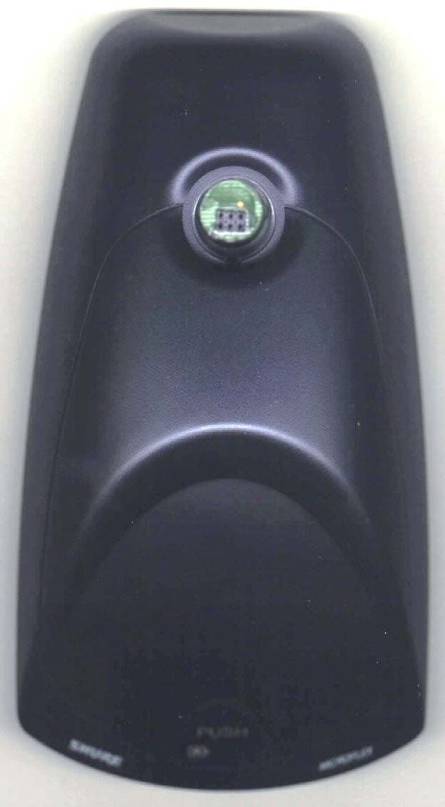
Click to zoom
Application Details
- Equipment Class
- TNB - Licensed Non-Broadcast Station Transmitter
- Date of Grant
- Oct 25, 2007
- Application Purpose
- Original Equipment
- Date of Application
- Oct 24, 2007
- Equipment Note
- Wireless Desktop Base Microphone
- Frequency Range
- 572.00000000 - 596.00000000
- Company
- Shure Incorporated
- Country
- United States
Documents & Files
Document Text
Text extracted from the exhibit documents filed with the FCC. Open a document above to read the original.
Users Manual
Wireless Desktop Base The Shure MX890 desktop base for MX405 and MX410 gooseneck microphones offers cable-free installation for corporate boardrooms or other applications requiring flexible microphone configurations. The MX890 operates within the 518–865 MHz bands and is compatible with Shure SLX wireless systems. ©2007, Shure Incorporated 27EN3253 (Rev. 1) Model MX890 Printed in U.S.A. DRAFT 2 Features Sleek, low profile design Frequency agile, microprocessor controlled transmitter IR link to SLX receiver for automatic frequency synchronization Programmable frequency Group/Channel display Programmable mute function Operates on two AA batteries Compatible with all Shure SLX Wireless systems Supports Shure MX405 and MX410 Mini Gooseneck Microphones Commshield™ technology for protection from RF interference • • • • • • • • • DRAFT 3 Microphone Placement Place the MX890 no more than 25 cm (1 ft.) from the edge of the table. Aim the microphone toward the talker and away from loudspeakers and noise sources. Use one microphone for each talker. Pickup angle with a cardioid cartridge is 130° at –3 dB. Pickup angle with a supercardioid cartridge is 115° at –3 dB. Note: To minimize RF interference, maintain a distance of at least 0.3 m (1 ft.) between transmitters. In case of interference, increase the distance between transmitters or change channels. Receiver Make sure the receiver is within sight of the transmitter. Do not place receiver behind a metal barrier or any reflective surface. Refer to the SLX Wireless System User Guide for more information, or visit www.shure.com. 130º 30m (100ft) DRAFT 4 The low-cut filter attenuates frequencies below 150 Hz by 6 dB per octave. Low-Cut Filter Filter disabled (as supplied) Low-cut filter Connecting Gooseneck Align the pin on the microphone flange with the slot on the desktop base. Insert the gooseneck into the desktop base and lock it in place by rotating the gooseneck sleeve clockwise. 1. 2. DRAFT 5 Battery Installation Open the battery compartment as shown. Insert two1.5V “AA” batteries. Make sure the +/– terminals are properly oriented. Note: Alkaline batteries last up to 8 hours. Rechargeable, carbon- zinc and zinc-chloride batteries provide less operating time. 1. 2. Power Meter The battery meter on the LCD shows remaining battery life. Low Power Indicator Steady Red: Power low. Replace batteries immediately Pulsing Red: Batteries dead. Transmitter cannot be turned on until batteries are replaced. DRAFT 6 Press and hold the ON/OFF PROGRAM button for approximately 2 seconds. The LCD illuminates. To turn the transmitter off, press and hold the ON/OFF PROGRAM button again. Note: Use the button on the bottom of the transmitter to power it on without opening the battery compartment. 1. 2. Power On/Off DRAFT 7 Mute Button The mute button can be configured for toggle or momentary operation. Toggle (as supplied) The PUSH button toggles the microphone between active and muted states. NOTE: The microphone always powers up in the active state. Momentary There are two types of momentary operation: Push-to-Mute: The microphone is muted only while the button is pressed and held. Push-to-Talk: The microphone is active only while the button is pressed and held. To change between toggle and momentary: Hold the PUSH button and press the SELECT button. (Test the microphone to confirm the change.) To change between push-to-talk and push-to-mute: Set the button for momentary operation. Hold the SELECT button and press the PUSH button. 1. 2. Hold Hold DRAFT 8 Mute Indicator The desktop base illuminates the gooseneck microphone LED to indicate whether the microphone is active or muted. Refer to the following table: Microphone Status MX405 / MX410 Indicator MX405R / MX410R Light Ring ActiveGreenRed MutedRed/Flashing Green*Off/Flashing* + *To toggle between off and flashing, press PUSH and ON/OFF PROGRAM simultaneously. DRAFT 9 Microphone Status MX405 / MX410 Indicator MX405R / MX410R Light Ring ActiveGreenRed MutedRed/Flashing Green*Off/Flashing* Locking Settings Press ON/OFF PROGRAM and SELECT simultaneously to lock or unlock transmitter settings. When locked, the current settings cannot be manually changed. Note: Locking the transmitter settings does not disable IR frequency synchronization or the High Pass/Low Cut filter. To use with a logic enabled receiver, you must perform an automatic sync. The LCD flashes “log” during sync. Once in logic mode, the LCD flashes “log” when powered up. LOGIC MODE DRAFT 10 Power off all transmitters. Power on all receivers. Begin with the first transmitter. Open the battery cover and power it on. Aim the IR sensor at the first receiver IR port. The transmitter should be no more than 15 cm (6 in.) from the receiver. Press and hold the receiver SYNC button to send group and channel data to the transmitter. The red LED on the transmitter will stop flashing when programming is complete. Power off the first transmitter and repeat the synchronization with each additional transmitter and receiver pair. 1. 2. 3. 4. 5. Press and hold the transmitter SELECT button until the desired group number appears. Press SELECT again and release it when the desired channel number appears. 1. 2. Automatic Frequency Synchronization Manual Frequency Synchronization DRAFT 11 Troubleshooting If you encounter difficulty with the SLX Wireless System: Make sure both the transmitter and the receiver are turned on. Replace the battery if the battery LED is red. Make sure the Group/Channel settings for each transmitter- receiver pair are identical. Make sure there is an unobstructed line of sight between the transmitter and receiver. If necessary, reposition the receiver or decrease the distance between transmitter and receiver. Remove local sources of RF interference, such as computers or lighting equipment. Remove metal objects within 0.3 m (1 ft.) of the transmitter Note: Refer to the SLX Wireless System User Guide for complete troubleshooting procedures. • • • •…
Text truncated - open the document above for the full version.
Users Manual
17 Certified to FCC Part 74 (FCC ID: DD4MX890). Certified by IC in Canada under RSS-123 and RSS-102 (IC: 616A-MX890). Meets essential requirements of the European R&TTE Directive 99/5/EC (ETSI EN 300-422 Parts 1 & 2, EN 301 489 Parts 1 & 9) and eligible to carry the CE marking. Changes or modifications not expressly approved by Shure Incorporated could void your authority to operate this equipment. Certification DRAFT
Cover Letter(s)
Request for Confidentiality Date: October 9, 2007 American Telecommunications Certification Body, Inc. 6731 Whittier Avenue Suite C110 McLean, VA 22101 RE: Certification Application FCC ID: DD4MX890J3 Pursuant to 47 CFR Section 0.459 Shure, Incorporated understands that requests for non disclosure and confidential treatment is being made for the following information as stated under the Code of Federal Regulations Chapter 47, Part 0.459 and behalf of APPLICANT NAME: • Description of Operation • Block Diagram • Schematics • Parts Lists The above materials contain trade secrets, proprietary and technical information that would customarily be guarded from competitors under 47 CFR section 0.457(d)(2). Disclosure or publication of any portion of this company confidential material to other parties could cause substantial competitive harm and provide unjustified benefits for competitors. Shure, Incorporated understands that pursuant to 47 CFR section 0.457(d)(1)(ii) disclosure of the applicant and all accompanying documentation will not be made before the date of the grant. Thank you for your attention to this matter. Signatory Arnom C. Rowe EMC ENGINEER EMC-001375-NE D.L.S. Electronic Systems, Inc.
Cover Letter(s)
Letter of Agency Date: October 9, 2007 American Telecommunications Certification Body, Inc. 6731 Whittier Avenue Suite C110 McLean, VA 22101 To Whom It May Concern: Please be advised that Shure, Incorporated authorizes D.L.S. Electronic Systems, Inc. to act on our behalf, until otherwise notified, for applications submitted to American Telecommunications Certification Body, Inc. (ATCB). We certify that we are not subject to denial of federal benefits, that includes FCC benefits, pursuant to Section 5301 of the Anti-Drug Abuse ACT of 1988, U.S.C. 862. Further, no party, as defined in 47 CFR 1.2002(b), to the application is subject to denial of federal benefits, that includes FCC benefits. Thank you for your attention to this matter. Signatory, Arnom C. Rowe EMC ENGINEER EMC-001375-NE D.L.S. Electronic Systems, Inc. FCC Labeling Requirements and Information Date: October 9, 2007 American Telecommunications Certification Body, Inc. 6731 Whittier Avenue Suite C110 McLean, VA 22101 RE: FCC Labeling Requirements FCC ID: DD4MX890J3 The following label information is required by the FCC Rules and Regulations for certified devices. Also attached, please find marketing information required by the FCC Rules and Regulations. Thank you for your attention to these matters. Sincerely, Arnom C. Rowe EMC ENGINEER EMC-001375-NE D.L.S. Electronic Systems, Inc. Modification Letter Date: October 9, 2007 American Telecommunications Certification Body, Inc. 6731 Whittier Avenue Suite C110 McLean, VA 22101 RE: Certification Application FCC ID: DD4MX890J3 Please be advised that the following information is a list of modifications that will be included in the production process for the above-referenced equipment. Change 1: There were no modifications made during testing. Change 2: Change 3: Change 4: Change 5: Change 6: Change 7: Change 8: Change 9 Change 10: Thank you for your attention to this matter. Signatory Arnom C. Rowe EMC ENGINEER EMC-001375-NE D.L.S. Electronic Systems, Inc. Manufacturer’s Letter Date: October 9, 2007 American Telecommunications Certification Body, Inc. 6731 Whittier Avenue Suite C110 McLean, VA 22101 RE: Certification Application FCC ID: DD4MX890J3 To Whom It May Concern: Please be advised that the manufacturer will ensure that the above-referenced model will be manufactured in accordance with the FCC Rules and Regulations. Thank you for your attention to this matter. Signatory Arnom C. Rowe EMC ENGINEER EMC-001375-NE D.L.S. Electronic Systems, Inc.
External Photos
Company: Shure, Inc. Model: MX890 Date: 07-24-2007 Photo Description: Top Company: Shure, Inc. Model: MX890 Date: 07-24-2007 Photo Description: Bottom Battery cover is hinged and not intended to be user removable.
Internal Photos
Company: Shure, Inc. Model: MX890 Date: 07-24-2007 Photo Description: Battery cover removed Company: Shure, Inc. Model: MX890 Date: 07-24-2007 Photo Description: Display / battery compartment removed Company: Shure, Inc. Model: MX890 Date: 07-24-2007 Photo Description: PCB 1, display side, with shield Company: Shure, Inc. Model: MX890 Date: 07-24-2007 Photo Description: PCB 1, side 1, shield removed Company: Shure, Inc. Model: MX890 Date: 07-24-2007 Photo Description: PCB 1, side 2 Company: Shure, Inc. Model: MX890 Date: 07-24-2007 Photo Description: PCB 2, side 1 Company: Shure, Inc. Model: MX890 Date: 07-24-2007 Photo Description: PCB 2, side 2 Company: Shure, Inc. Model: MX890 Date: 07-24-2007 Photo Description: Inside covers Company: Shure, Inc. Model: MX890 Date: 07-24-2007 Photo Description: Microphone booms
Internal Photos
NOTE: The wedge on the far left and right sides are used to prevent battery compartment door removal. NOTE: The wedge on the far left and right sides are used to prevent battery compartment door removal. NOTE: The wedge on the far right side that is used to prevent a screwdriver from removing the battery compartment door. NOTE: Another view showing the wedge that is used to prevent a screwdriver from removing the battery compartment door.
Test Report
1250 Peterson Dr., Wheeling, IL 60090 Company: Shure Incorporated Model Tested: MX890J3 Report Number: 13485 FCC Rules and Regulations / Intentional Radiators Low Power Auxiliary Stations Part 74, Subpart H, Sections 74.801 - 74.882 Part 74.861 (d) Other than TV Broadcasting THE FOLLOWING ''MEETS'' THE ABOVE TEST SPECIFICATION Formal Name: Wireless Desktop Base Kind of Equipment: Wireless Microphone Transmitter Base Test Configuration: Stand Alone with Microphone Gooseneck (Tested at 3 vdc) Model Number(s): MX890J3 Model(s) Tested: MX890J3 Serial Number(s): NA Emission Designator: 120KF3E Date of Tests: July 12, 13, 18 & 19, 2007 Test Conducted For: Shure Incorporated 5800 West Touhy Ave. Niles, Illinois 60714-4608 NOTICE: “This report must not be used by the client to claim product endorsement by NVLAP or any agency of the U.S. Government”. Please see the "Additional Description of Equipment Under Test" page listed inside of this report. © Copyright 1983- 2006 D.L.S. Electronic Systems, Inc COPYRIGHT NOTICE This report or any portion their of, may not be reproduced or modified in any form without the expressed written consent of D.L.S. Electronic Systems, Inc. Page -1 of 65- 1250 Peterson Dr., Wheeling, IL 60090 Company: Shure Incorporated Model Tested: MX890J3 Report Number: 13485 SIGNATURE PAGE Report By: Arnom C. Rowe Test Engineer EMC-001375-NE Reviewed By: William Stumpf OATS Manager Approved By: Brian Mattson General Manager Company Official: Shure Incorporated Page -2 of 65- 1250 Peterson Dr., Wheeling, IL 60090 Company: Shure Incorporated Model Tested: MX890J3 Report Number: 13485 TABLE OF CONTENTS i. Cover Page .......................................................................................................................................... 1 ii. Signature Page .................................................................................................................................... 2 iii. Table of Contents ............................................................................................................................ 3 iv. NVLAP Certificate of Accreditation .............................................................................................. 5 1.0 Summary of Test Report ................................................................................................................. 6 2.0 Introduction..................................................................................................................................... 6 3.0 Object .............................................................................................................................................. 6 4.0 Test Set-Up ..................................................................................................................................... 7 5.0 Test Equipment ............................................................................................................................... 8 6.0 Ambient Measurements .................................................................................................................. 9 7.0 AC Power Line Conducted Emission Measurements ..................................................................... 9 8.0 Description of Test Sample........................................................................................................... 10 9.0 Photo Information and Test Set-Up .............................................................................................. 11 10.0 Radiated Photos Taken During Testing ........................................................................................ 12 10.0 RF Conducted Photos Taken During Testing ............................................................................... 16 11.0 Results of Tests ............................................................................................................................. 17 12.0 Conclusion .................................................................................................................................... 17 TABLE 1 – EQUIPMENT LIST .............................................................................................................. 18 Page -3 of 65- 1250 Peterson Dr., Wheeling, IL 60090 Company: Shure Incorporated Model Tested: MX890J3 Report Number: 13485 TABLE OF CONTENTS Appendix A – Electric Field Radiated Emissions Test............................................................................. 20 1.0 Test Set-Up ................................................................................................................................... 21 2.0 RF Power Output .......................................................................................................................... 21 2.0 Data and Graph(s) taken of the RF Power Output ........................................................................ 22 3.0 RF Power Output Photos Taken During Testing .......................................................................... 26 4.0 Modulation Characteristics ........................................................................................................... 27 4.0 Graph(s) taken of the Modulation Characteristics ........................................................................ 28 5.0 Occupied Bandwidth..................................................................................................................... 32 5.0 Data and Graph(s) taken of the 99% Occupied Bandwidth .......................................................... 33 5.0 Data and Graph(s) taken of the Emission Mask ........................................................................... 37 6.0 Spurious Emissions At Antenna Terminals .................................................................................. 47 7.0 Field Strength of Spurious Emission Measurements .................................................................... 48 7.0 Radiated Data and Charts ta…
Text truncated - open the document above for the full version.
Contact Information
Applicant
Craig Kozokar(EMC Project Engineer)
Technical Specifications
| # | Rule Parts | Frequency Range | Power Output | Emission | Tolerance |
|---|---|---|---|---|---|
| 1 | 74 | 572 MHz - 596 MHz | 7.00 mW | 120KF3E | 10.0000000000 ppm |
Other Applications from Shure Incorporated
DD4IMXBP
Dec 24, 2025UC Wall
Equipment Class
NII - Unlicensed National Information Infrastructure TXDD4SLXD3EG57
Jul 25, 2025Plug-on Wireless Transmitter
Equipment Class
DTS - Digital Transmission System
DD4ULXD8G50
Sep 18, 2024Wireless Gooseneck Transmitter
Equipment Class
DWM - Part 15 Wireless Microphone
DD4ULXD8H50
Sep 18, 2024Wireless Gooseneck Transmitter
Equipment Class
DWM - Part 15 Wireless Microphone
DD4ULXD6G50
Sep 08, 2024Wireless Boundary Transmitter
Equipment Class
TLD - Licensed LPAS Device