DD4P7TAWireless Personal Monitor System
Shure Incorporated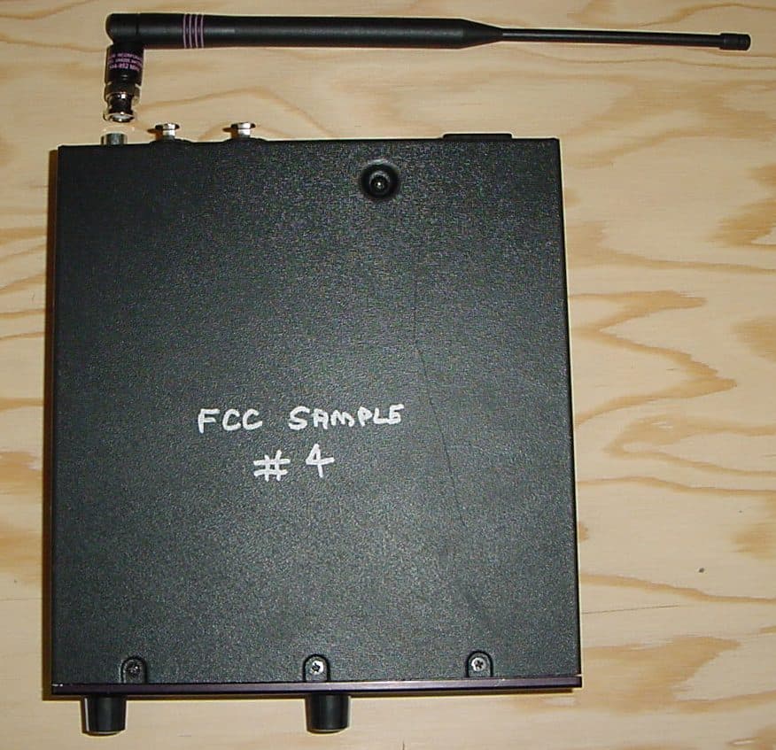
Click to zoom
Application Details
- Equipment Class
- TNB - Licensed Non-Broadcast Station Transmitter
- Date of Grant
- Mar 19, 2008
- Application Purpose
- Original Equipment
- Date of Application
- Mar 19, 2008
- Equipment Note
- Wireless Personal Monitor System
- Frequency Range
- 944.00000000 - 952.00000000
- Company
- Shure Incorporated
- Country
- United States
Documents & Files
Document Text
Text extracted from the exhibit documents filed with the FCC. Open a document above to read the original.
Users Manual
Model PSM ® 700 User Guide 27E8659 (Rev. 5) ©2007 Shure Incorporated Printed in U.S.A. Wireless Personal Monitor System User Guide Système de retour personnel sans fil Guide de l’utilisateur Drahtloses individuelles Monitorsystem Bedienungsanleitung Sistema de monitor personal inalámbrico Guía del usuario Radiosistema di controllo personale Guida all’uso PSM ® 700 ! IMPORTANT SAFETY INSTRUCTIONS ! 1.READ these instructions. 2.KEEP these instructions. 3.HEED all warnings. 4.FOLLOW all instructions. 5.DO NOT use this apparatus near water. 6.CLEAN ONLY with dry cloth. 7.DO NOT block any ventilation openings. Install in accordance with the manu- facturer's instructions. 8.DO NOT install near any heat sources such as radiators, heat registers, stoves, or other apparatus (including amplifiers) that produce heat. 9.DO NOT defeat the safety purpose of the polarized or grounding-type plug. A polarized plug has two blades with one wider than the other. A grounding type plug has two blades and a third grounding prong. The wider blade or the third prong are provided for your safety. If the provided plug does not fit into your out- let, consult an electrician for replacement of the obsolete outlet. 10.PROTECT the power cord from being walked on or pinched, particularly at plugs, convenience receptacles, and the point where they exit from the apparatus. 11.ONLY USE attachments/accessories specified by the manufacturer. 12. 13.UNPLUG this apparatus during lightning storms or when unused for long periods of time. 14.REFER all servicing to qualified service personnel. Servicing is required when the apparatus has been damaged in any way, such as power-supply cord or plug is dam- aged, liquid has been spilled or objects have fallen into the apparatus, the apparatus has been exposed to rain or moisture, does not operate normally, or has been dropped. 15.DO NOT expose the apparatus to dripping and splashing. DO NOT put objects filled with liquids, such as vases, on the apparatus. 16.The MAINS plug or an appliance coupler shall remain readily operable. 17.The airborne noise of the apparatus does not exceed 70dB (A). 18.Apparatus with CLASS I construction shall be connected to a MAINS socket outlet with a protective earthing connection. 19.To reduce the risk of fire or electric shock, do not expose this apparatus to rain or moisture. 20.Do not attempt to modify this product. Doing so could result in personal injury and/or product failure. This symbol indicates that dangerous voltage constituting a risk of electric shock is present within this unit. This symbol indicates that there are important operating and maintenance instructions in the literature accompanying this unit. WARNING! USING THIS SYSTEM AT EXCESSIVE VOLUMES CAN CAUSE PERMANENT HEARING DAMAGE. USE AS LOW A VOLUME AS POSSIBLE. In order to use this system safely, avoid prolonged listening at excessive sound pressure levels. Please use the following guidelines established by the Occupational Safety Health Administration (OSHA) on maximum time exposure to sound pressure levels before hearing damage occurs. 90 dB SPL at 8 hours 95 dB SPL at 4 hours 100 dB SPL at 2 hours 105 dB SPL at 1 hour 110 dB SPL at ½ hour 115 dB SPL at 15 minutes 120 dB SPL — avoid or damage may occur It is difficult to measure the exact Sound Pressure Levels (SPL) present at the eardrum in live applications. In addition to the volume setting on the PSM, the SPL in the ear is affected by ambient sound from floor wedges or other devices. The isolation provided by the fit of quality earpieces is also an important factor in determining the SPL. Here are some general tips to follow in the use of this product to protect your ears from damage. •Turn up the volume control only far enough to hear properly. •Ringing in the ears may indicate that the gain levels are too high. Try lowering the gain levels. Have your ears checked by an audiologist on a regular basis. If you experience wax buildup in your ears, stop using the system until an audiologist has examined your ears. •Wipe the ear molds with an antiseptic before and after use to avoid infections. Stop using the earphones if they are causing great discomfort or infection. USE only with a cart, stand, tripod, bracket, or table specified by the manufacturer, or sold with the apparatus. When a cart is used, use caution when moving the cart/apparatus combination to avoid injury from tip-over. English - 1 Quickstart P7T Transmitter Setup 1.Connect the transmitter to a power outlet using the supplied power cord. NOTE: Keep wall plug or rear power cord connection readily accessible. To completely remove power to the unit, unplug from wall or detachable rear power cord connection. 2.Attach the supplied antenna to the ANTENNA OUT BNC connector. 3.Connect an audio source, such as a mixer, to the audio inputs of the transmitter. You can use both input jacks or choose either one for a mono source. NOTE: All inputs are phantom power protected up to 60 VDC. 4.Set the PAD switch to either +4 dB or –10 dB depending on the signal level from the audio source. 5.Turn on the transmitter. 6.Set the SOURCE switch to MONO if you are using only one input. Otherwise set it to STEREO/MixMode. 7.Set the GROUP switch UP to group 1. 8.Set the CHANNEL dial to an unused channel. NOTE: See Selecting Channels. 9.Power on the audio source and adjust the level control until the LEDs are in the –3 dB to +3 dB range. P7R Receiver Setup 10.Attach the antenna to the ANTENNA connector. Use the red dot to align the threads. 11.Insert a 9V alkaline battery. 12.Set the DIP switches (See Dip Switches) 13.Set the channel to the same one as the transmitter. 14.Set the balance control to the center detent position. 15.Plug in the earphones and insert the earphones into your ears. 16.Turn the receiver on by rotating the volume dial clockwise past the click. NOTE: If you do not hear anything, check the RF LED on the transmitter to make sure it is receiving the radio signal from the…
Text truncated - open the document above for the full version.
Users Manual
©2007 Shure Incorporated Printed in USA 27A8899 (Rev. 1) PSM700 User Guide Supplement: X1 INTER-GROUP AVAILABILITY: PSM700 X1 944-952MHz The following table describes compatible Frequencies and Channels available within each group. Channel Group 1 Channel Group 2 0944.125 Full range, Robust, 6 channels 0951.875 Full range, Robust, 6 channels 1945.275 1950.725 2946.675 2949.325 3948.525 3947.475 4950.625 4945.375 5951.425 5944.575 6944.175 Full range, Maximum, 10 channels 6944.250 Full range, Maximum, 10 channels 7944.975 7945.050 8945.600 8945.675 9946.625 9946.700 A947.325 A947.400 B948.575 B948.650 C949.325 C949.400 D950.275 D950.350 E950.950 E951.025 F951.800 F951.875 ACCESSORIES Furnished: PA710X Receiver Antenna P7R-X1 (944-952Mhz) Furnished: UA400 Transmitter Antenna P7T-X1 (944-952MHz) COMPLIANCE INFORMATION Type accepted under FCC Part 74, FCC ID DD4P7TA.
Cover Letter(s)
FCC ID: DD4P7TA D.L.S. ELECTRONIC SYSTEMS, INC. 1250 Peterson Drive Wheeling, Illinois 60090 March 4, 2008 FCC Authorization & Evaluation Division 7435 Oakland Mills Road Columbia, Maryland 21045-0429 Gentlemen: We are submitting for Shure, Inc., an P7T Transmitter, Model Number P7TP-X1, with a FCC ID: DD4P7TA for certification. This unit has been tested and complies to Part 74 Subpart H. If there are any questions in regards to this application, please call D.L.S. Electronic Systems, Inc. at (847) 537 6400. Enclosed you will find a copy of our test report with the information and results of tests that is required under Part 74.886(d). Thank you for your assistance in this matter. Sincerely, Arnom C. Rowe EMC-001375-NE DLS/cp
Cover Letter(s)
Request for Confidentiality Date: March 4, 2008 American Telecommunications Certification Body, Inc. 6731 Whittier Avenue Suite C110 McLean, VA 22101 RE: Certification Application FCC ID: DD4P7TA Pursuant to 47 CFR Section 0.459 Shure, Inc. understands that requests for non disclosure and confidential treatment is being made for the following information as stated under the Code of Federal Regulations Chapter 47, Part 0.459 and behalf of APPLICANT NAME: • Block Diagram • Schematics • Technical Product Description • Parts Lists The above materials contain trade secrets, proprietary and technical information that would customarily be guarded from competitors under 47 CFR section 0.457(d)(2). Disclosure or publication of any portion of this company confidential material to other parties could cause substantial competitive harm and provide unjustified benefits for competitors. Shure, Inc. understands that pursuant to 47 CFR section 0.457(d)(1)(ii) disclosure of the applicant and all accompanying documentation will not be made before the date of the grant. Thank you for your attention to this matter. Signatory Arnom C. Rowe EMC ENGINEER EMC-001375-NE D.L.S. Electronic Systems, Inc.
Cover Letter(s)
Letter of Agency Date: March 4, 2008 American Telecommunications Certification Body, Inc. 6731 Whittier Avenue Suite C110 McLean, VA 22101 To Whom It May Concern: Please be advised that Shure, Inc. authorizes D.L.S. Electronic Systems, Inc. to act on our behalf, until otherwise notified, for applications submitted to American Telecommunications Certification Body, Inc. (ATCB). We certify that we are not subject to denial of federal benefits, that includes FCC benefits, pursuant to Section 5301 of the Anti-Drug Abuse ACT of 1988, U.S.C. 862. Further, no party, as defined in 47 CFR 1.2002(b), to the application is subject to denial of federal benefits, that includes FCC benefits. Thank you for your attention to this matter. Signatory, Arnom C. Rowe EMC ENGINEER EMC-001375-NE D.L.S. Electronic Systems, Inc. FCC Labeling Requirements and Information Date: March 4, 2008 American Telecommunications Certification Body, Inc. 6731 Whittier Avenue Suite C110 McLean, VA 22101 RE: FCC Labeling Requirements FCC ID: DD4P7TA The following label information is required by the FCC Rules and Regulations for certified devices. Also attached, please find marketing information required by the FCC Rules and Regulations. Thank you for your attention to these matters. Sincerely, Arnom C. Rowe EMC ENGINEER EMC-001375-NE D.L.S. Electronic Systems, Inc. Modification Letter Date: March 4, 2008 American Telecommunications Certification Body, Inc. 6731 Whittier Avenue Suite C110 McLean, VA 22101 RE: Certification Application FCC ID: DD4P7TA Please be advised that the following information is a list of modifications that will be included in the production process for the above-referenced equipment. Change 1: There were no modifications made during testing. Change 2: Change 3: Change 4: Change 5: Change 6: Change 7: Change 8: Change 9 Change 10: Thank you for your attention to this matter. Signatory Arnom C. Rowe EMC ENGINEER EMC-001375-NE D.L.S. Electronic Systems, Inc. Manufacturer’s Letter Date: March 4, 2008 American Telecommunications Certification Body, Inc. 6731 Whittier Avenue Suite C110 McLean, VA 22101 RE: Certification Application FCC ID: DD4P7TA To Whom It May Concern: Please be advised that the manufacturer will ensure that the above-referenced model will be manufactured in accordance with the FCC Rules and Regulations. Thank you for your attention to this matter. Signatory Arnom C. Rowe EMC ENGINEER EMC-001375-NE D.L.S. Electronic Systems, Inc.
External Photos
Company: Shure, Inc. Model: P7T-X1 Date: 01-29-2008 Photo Description: Top Company: Shure, Inc. Model: P7T-X1 Date: 01-29-2008 Photo Description: Bottom Company: Shure, Inc. Model: P7T-X1 Date: 01-29-2008 Photo Description: Front Company: Shure, Inc. Model: P7T-X1 Date: 01-29-2008 Photo Description: Back
ID Label/Location Info
Company: Shure, Inc. Model: P7T-X1 Date: 01-29-2008 Photo Description: Back
Internal Photos
Company: Shure, Inc. Model: P7T-X1 Date: 01-29-2008 Photo Description: Top cover removed Company: Shure, Inc. Model: P7T-X1 Date: 01-29-2008 Photo Description: Inside covers Company: Shure, Inc. Model: P7T-X1 Date: 01-29-2008 Photo Description: Circuit board - side 1 Company: Shure, Inc. Model: P7T-X1 Date: 01-29-2008 Photo Description: Circuit board - side 1 - shield removed Company: Shure, Inc. Model: P7T-X1 Date: 01-29-2008 Photo Description: Circuit board - side 2
Parts List/Tune Up Info
Description: P7T-NF TRANSMITTER (539-662, 944-952 Mhz) DRWG : P7T-NF-7-BX_PRELIM Refer To Drawing NOS. 90-10603, 90-11423 Page 10 of 30 ISS Record of Changes Made 1. Production Release 12/4/03 2 ECO 82979: Updated II Circuit Description, IV Alignment procedure, added XII IF Receiver Modification for P7R- NF. JMM 04/30/04 5/20/04 CJW 3. ECO 82960: Widened Regulator limits for 12V & 5V. JMM. 8/27/04 4. ECO 100150. On Refer Drwg. 90-10603 was 90-8963-11. Deleted 90-8963-3. AMS CONFIDENTIAL © 2003 – 2006 SHURE INCORPORATED SHURE INCORPORATED. 5800 TOUHY AVENUE NILES, IL 60714-4608 PHONE 847-600-2000 Microphones-Electronic Components Typed: C. Babarskas 11/25/03 S. Brumm, J. R. Haugland 2/11/08 Checked: Y. Tang 11/25/03 J. R. Haugland 2/11/08 Approved: SMG 12-2-03 T. Liao 2/ /08 III Test Equipment Required Test Equipment (or approved equivalent) 1. Digital Multimeter Fluke 77 or 87 2. Audio Oscillator Krohn Hite 4300A or HP8903 3. AC Meter HP8903, HP400GL, or Tektronix AA501 4. Distortion Analyzer HP8903,Tektronix AA501(4) 50Ω loads 5. Frequency Counter Phillips PM6666 or HP5386A 6. Spectrum Analyzer HP8591A with tracking generator 7. IF Receiver Shure Modified P6R Design 8. Two RF Signal Generators Hewlett Packard 8657A 9. 50 ohm cable(RG-58/U), 2ft or less,BNC to BNC connector 11. XLR-to-1/4in. cable Shure Part #: 90A8756/1 10. RF Mixer(ZAD-1) 11. Non-metallic slot-type screw driver. (Toray yellow adjuster #A-1810) 12. Non-metallic slot-type screw driver. (Toray red adjuster #A-0910) IV Alignment Procedure PREFACE: Connect a 50 ohm coaxial cable from antenna BNC jack J3 to a spectrum analyzer. If any part of the following alignment cannot be achieved, see Section X, “Service Evaluation and Troubleshooting”. Initial Transmitter Settings 1. Set Power Switch (SW2) to ON (in) when testing on the bench, OFF (out) when testing in the production fixture. 2. Set Stereo/Mono switch (SW1) to “Stereo” (down) 3. Set input level control (R202) full clockwise. 4. Set headphone volume control (R136) full clockwise. 5. Set voltage selector switch (SW4) for 115V(160mA fuse) when testing in the United States. Set (SW4) for 230V(80mA fuse) when testing in other countries, based on their AC power standard. 6. Apply AC power based on your country’s AC power standard. Use a power line cord when bench testing. In production, apply +20V to TP222, and -20VDC to TP224. 7. Set input pad (SW3) for -10dB. 8. Set audio analyzer with a 30kHz low pass filter. 9. Attach XLR-to-1/4in. cable (90A8756) from “Left Loop OUT” to “Right/CH2 IN”. Description: P7T-NF TRANSMITTER (539-662, 944-952 Mhz) DRWG : P7T-NF-7-BX_PRELIM Refer To Drawing NOS. 90-10603, 90-11423 Page 11 of 30 ISS Record of Changes Made 1. Production Release 12/4/03 2 ECO 82979: Updated II Circuit Description, IV Alignment procedure, added XII IF Receiver Modification for P7R- NF. JMM 04/30/04 5/20/04 CJW 3. ECO 82960: Widened Regulator limits for 12V & 5V. JMM. 8/27/04 4. ECO 100150. On Refer Drwg. 90-10603 was 90-8963-11. Deleted 90-8963-3. AMS CONFIDENTIAL © 2003 – 2006 SHURE INCORPORATED SHURE INCORPORATED. 5800 TOUHY AVENUE NILES, IL 60714-4608 PHONE 847-600-2000 Microphones-Electronic Components Typed: C. Babarskas 11/25/03 S. Brumm, J. R. Haugland 2/11/08 Checked: Y. Tang 11/25/03 J. R. Haugland 2/11/08 Approved: SMG 12-2-03 T. Liao 2/ /08 MODEL:P7T-H3 All frequencies listed below are in units of MHz. Model H3 ROTARY SWITCH SW8 POSITION. Group 1 SW7 UP Group 2 SW7 DOWN 0 524.200 553.800 1 525.150 552.850 2 526.825 551.175 3 530.375 547.625 4 531.000 547.000 5 533.300 544.700 6 538.150 539.850 7 545.625 532.375 8 546.925 531.075 9 550.150 527.850 A 551.625 535.025 B 553.575 541.65 C 537.325 536.350 D 527.975 543.250 E 540.675 551.125 F 542.725 553.375 TABLE 1 Description: P7T-NF TRANSMITTER (539-662, 944-952 Mhz) DRWG : P7T-NF-7-BX_PRELIM Refer To Drawing NOS. 90-10603, 90-11423 Page 12 of 30 ISS Record of Changes Made 1. Production Release 12/4/03 2 ECO 82979: Updated II Circuit Description, IV Alignment procedure, added XII IF Receiver Modification for P7R- NF. JMM 04/30/04 5/20/04 CJW 3. ECO 82960: Widened Regulator limits for 12V & 5V. JMM. 8/27/04 4. ECO 100150. On Refer Drwg. 90-10603 was 90-8963-11. Deleted 90-8963-3. AMS CONFIDENTIAL © 2003 – 2006 SHURE INCORPORATED SHURE INCORPORATED. 5800 TOUHY AVENUE NILES, IL 60714-4608 PHONE 847-600-2000 Microphones-Electronic Components Typed: C. Babarskas 11/25/03 S. Brumm, J. R. Haugland 2/11/08 Checked: Y. Tang 11/25/03 J. R. Haugland 2/11/08 Approved: SMG 12-2-03 T. Liao 2/ /08 MODEL:P7T-L2 All frequencies listed below are in units of MHz. Model L2 ROTARY SWITCH SW8 POSITION. Group 1 SW7 UP Group 2 SW7 DOWN 0 632.200 661.800 1 633.150 660.850 2 634.825 659.175 3 638.375 655.625 4 639.000 655.000 5 641.300 652.700 6 646.150 647.850 7 653.625 640.375 8 654.925 639.075 9 658.150 635.850 A 659.625 643.025 B 661.575 649.65 C 645.325 644.350 D 635.975 651.250 E 648.675 659.125 F 650.725 661.375 TABLE 2 Description: P7T-NF TRANSMITTER (539-662, 944-952 Mhz) DRWG : P7T-NF-7-BX_PRELIM Refer To Drawing NOS. 90-10603, 90-11423 Page 13 of 30 ISS Record of Changes Made 1. Production Release 12/4/03 2 ECO 82979: Updated II Circuit Description, IV Alignment procedure, added XII IF Receiver Modification for P7R- NF. JMM 04/30/04 5/20/04 CJW 3. ECO 82960: Widened Regulator limits for 12V & 5V. JMM. 8/27/04 4. ECO 100150. On Refer Drwg. 90-10603 was 90-8963-11. Deleted 90-8963-3. AMS CONFIDENTIAL © 2003 – 2006 SHURE INCORPORATED SHURE INCORPORATED. 5800 TOUHY AVENUE NILES, IL 60714-4608 PHONE 847-600-2000 Microphones-Electronic Components Typed: C. Babarskas 11/25/03 S. Brumm, J. R. Haugland 2/11/08 Checked: Y. Tang 11/25/03 J. R. Haugland 2/11/08 Approved: SMG 12-2-03 T. Liao 2/ /08 Model X1 Rotary Switch Group 1 SW7 UP Group 2 SW7 Down 0 944.125951.875 1 945.275950.725 2 946.675949.325 3 948.525947.475 4 950.625945.375 5 951.425944.575 6 944.175944.250 7 944.975945.050 8 945.600945.675 9 946.625946.700 A 947.325947.400 …
Text truncated - open the document above for the full version.
RF Exposure Info
RF Exposure Statement 1. Standard Applicable According to 1.1307 (b)(1), systems operating under the provisions of this section shall be operated in a manner that ensure that the public is not exposed to radio frequency energy level in excess of the Commission’s guideline. This is a mobile device. 2. Measurement Result: This is a mobile device and the max peak output power is 180.3 mW. S = PG 4πR 2 S = power density (units e.g. mW/cm 2 ) P = power into to the antenna (or power output) (units e.g. mW) G = power gain of the antenna (worst case = 1) R = distance to the center of antenna (units e.g. cm) S = 180.3 x 1 4x3.14x20 2 S = .036 mW Limit of General Population/uncontrolled Exposure = f/1500 MHz = (.635 mW) d<20 cm general population category. The SAR measurement is not necessary.
Test Report
1250 Peterson Dr., Wheeling, IL 60090 Page -1 of 81- Company: Shure Inc. Model Tested: P7T-X1 Report Number: 13885 FCC Rules and Regulations / Intentional Radiators Low Power Auxiliary Stations Part 74, Subpart H, Sections 74.801 - 74.882 Part 74.861 (d) Other than TV Broadcasting THE FOLLOWING MEETS THE ABOVE TEST SPECIFICATION Formal Name: P7T Transmitter Kind of Equipment: Wireless Personal Monitor Transmitter Test Configuration: Through shielded audio frequency cables (Tested at 120 vac, 60 Hz) Model Number(s): P7T-X1 Model(s) Tested: P7T-X1 Serial Number(s): # 4 & # 5 Emission Designator: 79.8KF3E Date of Tests: January 24, 25, 28 & 29, 2008 Test Conducted For: Shure Inc. 5800 Touhy Ave Niles, Illinois 60714 NOTICE: “This report must not be used by the client to claim product endorsement by NVLAP or any agency of the U.S. Government”. Please see the "Additional Description of Equipment Under Test" page listed inside of this report. © Copyright 1983-2007 D.L.S. Electronic Systems, Inc COPYRIGHT NOTICE This report or any portion their of, may not be reproduced or modified in any form without the expressed written consent of D.L.S. Electronic Systems, Inc. 1250 Peterson Dr., Wheeling, IL 60090 Page -2 of 81- Company: Shure Inc. Model Tested: P7T-X1 Report Number: 13885 SIGNATURE PAGE Report By: Arnom C. Rowe Test Engineer EMC-001375-NE Reviewed By: William Stumpf OATS Manager Approved By: Brian Mattson General Manager 1250 Peterson Dr., Wheeling, IL 60090 Page -3 of 81- Company: Shure Inc. Model Tested: P7T-X1 Report Number: 13885 TABLE OF CONTENTS i. Cover Page ....................................................................................................................................... 1 ii. Signature Page .................................................................................................................................2 iii. Table of Contents .............................................................................................................................3 iv. NVLAP Certificate of Accreditation ...............................................................................................5 1.0 Summary of Test Report ..................................................................................................................6 2.0 Introduction......................................................................................................................................6 3.0 Object ...............................................................................................................................................6 4.0 Test Set-Up ......................................................................................................................................7 5.0 Test Equipment ................................................................................................................................8 6.0 Ambient Measurements ................................................................................................................... 9 7.0 AC Power Line Conducted Emission Measurements ....................................................................10 8.0 Description of Test Sample............................................................................................................11 9.0 Additional Description of Test Sample.......................................................................................... 11 10.0 Photo Information and Test Set-Up ...............................................................................................12 11.0 Radiated Photos Taken During Testing .........................................................................................13 11.0 RF Conducted Photos Taken During Testing ................................................................................ 15 11.0 AC Power Line Conducted Photos Taken During Testing ............................................................ 16 12.0 Results of Tests .............................................................................................................................. 17 13.0 Conclusion ..................................................................................................................................... 17 TABLE 1 – EQUIPMENT LIST ............................................................................................................... 18 1250 Peterson Dr., Wheeling, IL 60090 Page -4 of 81- Company: Shure Inc. Model Tested: P7T-X1 Report Number: 13885 Appendix A – Transmitter Emissions Tests ..............................................................................................23 1.0 Test Set-Up .................................................................................................................................... 24 2.0 RF Power Output ........................................................................................................................... 24 2.0 Data taken of the RF Power Output ...............................................................................................25 3.0 RF Output Power Photos Taken During Testing ........................................................................... 28 4.0 Modulation Characteristics ............................................................................................................ 29 4.0 Graph(s) taken of the Modulation Characteristics .........................................................................30 5.0 Occupied Bandwidth......................................................................................................................33 5.0 Data and Graph(s) taken of the 99% Occupied Bandwidth ...........................................................34 6.0 Spurious Emissions At Antenna Terminals ................................................................................... 37 6.0 Conducted Emission Data and Charts made at the Antenna Terminals ..........................…
Text truncated - open the document above for the full version.
Test Setup Photos
Company: Shure, Inc. Model: P7T-X1 Photo Description: Frequency Stability - Band Edge Company: Shure, Inc. Model: P7T-X1 Photo Description: Output Power Company: Shure, Inc. Model: P7T-X1 Photo Description: Radiated - Back Company: Shure, Inc. Model: P7T-X1 Photo Description: Radiated – Front Company: Shure, Inc. Model: P7T-X1 Photo Description: RF Conducted - Spurious Company: Shure, Inc. Model: P7T-X1 Photo Description: Line Conducted
Contact Information
Applicant
Craig Kozokar(EMC Project Engineer)
Technical Contact
D. L. S. Electronic Systems, Inc.Arnom (Arnie) Rowe
[email protected]847-537-6400
1250 Peterson Drive · Wheeling, Illinois · United States
Test Firm
DLS Electronic Systems, Inc.William Stumpf
Technical Specifications
| # | Rule Parts | Frequency Range | Power Output | Emission | Tolerance |
|---|---|---|---|---|---|
| 1 | 74 | 944 MHz - 952 MHz | 100.00 mW | 79K8F3E | 0.0050000000 % |
Other Applications from Shure Incorporated
DD4IMXBP
Dec 24, 2025UC Wall
Equipment Class
NII - Unlicensed National Information Infrastructure TXDD4SLXD3EG57
Jul 25, 2025Plug-on Wireless Transmitter
Equipment Class
DTS - Digital Transmission System
DD4ULXD8G50
Sep 18, 2024Wireless Gooseneck Transmitter
Equipment Class
DWM - Part 15 Wireless Microphone
DD4ULXD8H50
Sep 18, 2024Wireless Gooseneck Transmitter
Equipment Class
DWM - Part 15 Wireless Microphone
DD4ULXD6G50
Sep 08, 2024Wireless Boundary Transmitter
Equipment Class
TLD - Licensed LPAS Device