DD4PGXD2900 MHz ISM BAND TRANSMITTER
Shure Incorporated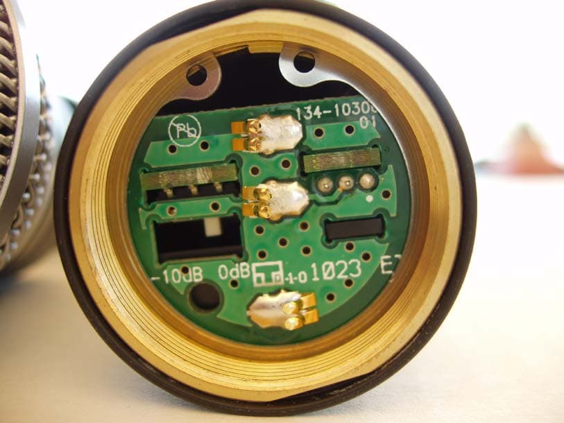
Click to zoom
Application Details
- Equipment Class
- DTS - Digital Transmission System
- Date of Grant
- Aug 29, 2010
- Application Purpose
- Original Equipment
- Date of Application
- Aug 29, 2010
- Equipment Note
- 900 MHz ISM BAND TRANSMITTER
- Frequency Range
- 902.75000000 - 927.25000000
- Company
- Shure Incorporated
- Country
- United States
Documents & Files
Document Text
Text extracted from the exhibit documents filed with the FCC. Open a document above to read the original.
Users Manual
Shure PGXD Wireless PGXD Wireless System PGXD sans fil de Shure Shure PGXD Sem Fio ©2010 Shure Incorporated 27A14513 (Rev. 1) Printed in U.S.A. PGX Digital Wireless Systems Offering uniquely tailored wireless solutions for vocalists, guitarists, and presenters, PGX-Digital combines the trusted legacy of Shure wired microphones with state-of-the-art, 24-bit digital wireless technology to deliver strong, clean RF performance. The result is wireless audio that sounds like wired, rock-steady RF signal even at extended distances, and plug-and-play setup and operation. • Professional quality 24-bit digital audio • Digital RF technology for rock-solid performance • Wide variety of rugged and dependable Shure microphones • One-touch setup and operation • Up to 10 hours of battery life (9 hours, PGXD2) • Up to 200 foot range (line-of-sight) • 900 MHz operation—free from white spaces or DTV interference System Components All systems include • PGXD4 receiver • 2 AA alkaline batteries • Power supply • User guide Vocalist systems include • PGXD2 handheld transmitter • Microphone head (choice of PG58, SM58 ® , SM86, Beta 58A ® or Beta 87A*) • Microphone clip * Available only in select markets Lavalier, Headworn, and Instrument systems include • PGXD1 bodypack transmitter • Microphone (choice of WL93, WL185, PG30 or Beta 98H/C) Receiver Controls and Connectors ① audio LED Indicates strength of incoming audio signal: green for normal, amber for strong and red for clipping. ② LED Screen Displays group and channel setting. See “Single System Setup” for details. ③ channel button Changes group and channel setting. See “Single System Setup” for details. ④ ready LED Indicates system ready and receiving an RF signal from the transmitter. Also indicates battery level of the transmitter: • Green = transmitter battery level normal • Red = low battery (typically less than 60 minutes with alkaline batteries) Note: with NiMH rechargeable batter- ies, when the indicator turns red there will be little to no remaining life. ⑤ Infrared (IR) port Sends IR signal to transmitter for sync. ⑥ sync button Press to synchronize transmitter with receiver group and channel settings. PGXD PGXD4 Guitar systems include • PGXD1 bodypack transmitter • 1/4” to mini 4-pin guitar cable (WA302) ⑦ AC adapter jack ⑧ Adapter cord tie-off ⑨ XLR microphone output jack ⑩ 6.35 mm (1/4”) instrument level output jack Transmitter Controls and Connectors ① Indicator LED Displays battery level, mute, and IR transmission status (see table). ② Power / Mute Switch Press to mute or unmute. Press and hold to power on or off. ③ Infrared (IR) port Receives infrared beam to synchronize frequencies. When using multiple systems, only one transmitter IR port should be exposed at a time. ④ 4-Pin Microphone Input Jack ⑤ Audio Gain Adjustment PGXD2 PGXD1 PGXD BIAS AUDIO 0dB -10dB PGXD LED IndicatorStatus GreenReady Flashing greenControls locked AmberMute on Solid redBattery power low Flashing redBatteries dead (change batteries to power on transmitter) Rapidly flashing redIR transmission in process Flashing amber and red Battery power low and mute on Transmitter Indicator LED INSTRUMENT MIC BIAS AUDIO 0dB -10dB AUDIO 0dB -10dB Wearing the Bodypack Transmitter Clip the transmitter to a belt or slide a guitar strap through the transmitter clip as shown. For best results, slide the transmitter until the belt is pressed against the base of the clip. Adjusting Gain Handheld Transmitter Access the gain switch by unscrewing the head of the microphone. Use the tip of a pen or a small screwdriver to move the switch. • 0dB: For quiet to normal vocal performance. • –10dB: Use only if audio is distorted due to high vocal levels. PGXD Batteries • A fresh set of alkaline batteries lasts up to 10 hours (9 hours, PGXD2). • The transmitter LED and the receiver ready LED glow red to indicate low battery (typically less than 60 minutes remaining). • NiMH rechargeable batteries may be used. However, the low battery indicator functions differently. When it turns red, there may be little to no remaining life. • When the LED flashes red, the batteries must be replaced to power on the transmitter. PGXD Bodypack Transmitter The bodypack has 26 dB of audio gain adjustment. • Increase gain (clockwise +) for microphones • Decrease gain (counterclockwise –) for guitars or high-output instruments For best audio quality, set transmitter gain so the audio LED on the receiver flickers green and amber during the performance. Decrease gain if the signal clips (LED turns red). Note: The amber LED may appear to be red when viewed at an angle. For best results, monitor the LED from directly in front. channel Single System Setup Scan Use the scan feature on the receiver to find a clear channel. LED screen displays current channel press channel button to scan for a clear channel system scans for the channel with the least interference Synchronize Synchronize the transmitter to the receiver by aligning the infrared (IR) ports and pressing the sync button. Make sure the IR ports are closely aligned. After a successful sync, the transmitter LED momentarily flashes red and the receiver ready light illuminates. Multiple System Setup NOTE: This wireless system may be affected by RF inter- ference when used in proximity to other wireless devices such as cordless phones, baby monitors, and two-way ra- dios. For best results, use the scan and sync feature before each use or if you experience problems. Use the following steps to ensure the best performance when installing multiple wire- less systems at the same location. 1. Turn all receivers on and all transmitters off. Note: Turn on any other digital equipment that could cause interference during the performance so it will be detected during the frequency scans in the following steps. 2. Make sure the group number is the same for all receivers (see Manual Group Selection). 3. Perform a scan using the first receiver. 4. Turn on the first transmitter and sync it …
Text truncated - open the document above for the full version.
Cover Letter(s)
August 20, 2010 Elite Electronic Engineering, Inc. 1516 Centre Circle Downers Grove, Illinois 60515-1082 SUBJECT: REQUEST FOR NON-DISCLOSURE FOR FCC ID: DD4PGXD2 To Whom It May Concern: Pursuant to 47 CFR Section 0.459, Shure Incorporated hereby requests non-disclosure and confidential treatment of the following materials submitted in support of FCC certification application for FCC ID # DD4PGXD2: a. Schematic Diagrams b. Operational Description c. Block Diagram d. Parts List e. Tune Up Procedure Above materials contain trade secrets, proprietary and technical information which would customarily be guarded from competitors under 47 CFR section 0.457(d)(2). Disclosure or publication of any portion of this company confidential material to other parties could cause substantial competitive harm and provide unjustified benefits for competitors. Shure Incorporated understands that pursuant to 47 CFR section 0.457(d)(1)(ii) disclosure of the applicant and all accompanying documentation will not be made before the date of the grant. Sincerely yours, Juan M. Castrejon Senior Engineer, Global Compliance Shure Incorporated
External Photos
Shure PGXD2 Handheld Wireless Microphone External Photographs PGXD2 Front PGXD2 Parts – Front PGXD2 – Back w/o Battery Cover PGXD2 Top PGXD2 Top with Microphone Head Removed PGXD2 Bottom w/ Battery Cover PGXD2 – Bottom w/o Battery Cover
Internal Photos
Shure PGXD2 Handheld Wireless Microphone Internal Photographs PGXD2 PCB Removed PGXD2 PCB Topside PGXD2 PCB Bottom Side PGXD2 MIC PCB
RF Exposure Info
RF SAFETY STATEMENT Date: 08/20/2010 To: Elite Electronics, Inc. 1516 Centre Circle Downers Grove, IL 60515-1082 From: Juan Castrejon Phone: 847-600-8651 Senior Engineer, Global Compliance Fax: 847-660-8555 Applicant: Shure Incorporated E-Mail: [email protected] ______________________________________________________________________ Dear Ladies and/or Gentlemen: The Shure Model PGXD2 Wireless Handheld Transmitter is intended to be held next to the face. The Effective Radiated Power of this device is under 50 mW. Dated this 20th day of August, 2010. By: Juan M. Castrejon Title: Senior Engineer, Global Compliance Phone: 847-600-8651 FAX: 847-600-8555
Test Report
Elite Electronic Engineering Inc. 1516 Centre Circle Downers Grove, IL 60515 Tel : (630) 495-9770 Fax: (630) 495-9785 www.elitetest.com For : Shure Incorporated : 5800 West Touhy Avenue : Niles, IL P.O. No. : 4500175587 Date Received : May 12, 2010 Date Tested : May 12, 2010 through May 13, 2010 Test Personnel : Mark E. Longinotti Specification : FCC "Code of Federal Regulations" Title 47, Part 15, Subpart C, Section 15.247 for Digital Modulation Intentional Radiators Operating within the band 902-928MHz : Industry Canada RSS-210 Industry Canada RSS-GEN Test Report By : Mark E. Longinotti Witnessed By : Juan Castrejon Shure Incorporated Approved By : Raymond J. Klouda Registered Professional Engineer of Illinois - 44894 Engineering Test Report No. 0901794-01 Measurement of RF Interference from an PGXD2 Wireless Microphone Transmitter Engineering Test Report No. 0901794-01 THIS REPORT SHALL NOT BE REPRODUCED, EXCEPT IN FULL, WITHOUT THE WRITTEN APPROVAL OF ELITE ELECTRONIC ENGINEERING INCORPORATED. Page 2 of 42 TABLE OF CONTENTS PARAGRAPH DESCRIPTION OF CONTENTS PAGE NO. 1 ............................................................................................................................................... 5 INTRODUCTION 1.1 .......................................................................................................................................... 5 Scope of Tests 1.2 .................................................................................................................................................... 5 Purpose 1.3 ....................................................................................................... 5 Deviations, Additions and Exclusions 1.4 .................................................................................................................. 5 EMC Laboratory Identification 1.5 .............................................................................................................................. 5 Laboratory Conditions 2 ............................................................................................................................ 5 APPLICABLE DOCUMENTS 3 .......................................................................................................... 6 TEST ITEM SET-UP AND OPERATION 3.1 .................................................................................................................................. 6 General Description 3.1.1 .......................................................................................................................................... 6 Power Input 3.1.2 ........................................................................................................................... 6 Peripheral Equipment 3.1.3 ............................................................................................................................. 6 Interconnect Cables 3.1.4 ............................................................................................................................................. 6 Grounding 3.2 ..................................................................................................................................... 6 Operational Mode 3.3 ............................................................................................................................. 6 Test Item Modifications 4 .......................................................................................... 6 TEST FACILITY AND TEST INSTRUMENTATION 4.1 ................................................................................................................................... 6 Shielded Enclosure 4.2 ................................................................................................................................. 6 Test Instrumentation 4.3 ............................................................................................................................. 6 Calibration Traceability 4.4 ........................................................................................................................ 6 Measurement Uncertainty 5 ....................................................................................................................................... 7 TEST PROCEDURES 5.1 .............................................................................................................. 7 Powerline Conducted Emissions 5.1.1 ....................................................................................................................................... 7 Requirements 5.2 .......................................................................................................................................... 7 6dB Bandwidth 5.2.1 ......................................................................................................................................... 7 Requirement 5.2.2 ........................................................................................................................................... 7 Procedures 5.2.3 .................................................................................................................................................. 7 Results 5.3 ................................................................................................................................... 7 Peak Output Power 5.3.1 ....................................................................................................................................... 7 Requirements 5.3.2 ........................................................................................................................................... 7 Procedures 5.3.3 .................................................................................................................................................. 8 Results 5.4 ..............................................................................................…
Text truncated - open the document above for the full version.
Test Setup Photos
Engineering Test Report No. 0901794-01 Figure 2 Test Setup for Radiated Emissions – 902MHz to 928MHz, Horizontal Polarization Test Setup for Radiated Emissions – 902MHz to 928MHz, Vertical Polarization Page 15 of 42 Engineering Test Report No. 0901794-01 Page 16 of 42 Engineering Test Report No. 0901794-01 Figure 3 Test Setup for Radiated Emissions – 1GHz to 10GHz, Horizontal Polarization Test Setup for Radiated Emissions – 1GHz to 18GHz, Vertical Polarization Page 17 of 42
Contact Information
Applicant
Craig Kozokar(EMC Project Engineer)
Technical Contact
SHURE IncorporatedJuan Castrejon
[email protected]847-600-8651
5800 W. Touhy Ave · Niles, Illinois · United States
Non-Technical Contact
SHURE IncorporatedThomas Braxton
[email protected]847-600-8582
Test Firm
Elite Electronic Engineering Inc.Kevin Halpin
Technical Specifications
| # | Rule Parts | Frequency Range | Power Output |
|---|---|---|---|
| 1 | 15C | 902.75 MHz - 927.25 MHz | 10.00 mW |
Other Applications from Shure Incorporated
DD4IMXBP
Dec 24, 2025UC Wall
Equipment Class
NII - Unlicensed National Information Infrastructure TXDD4SLXD3EG57
Jul 25, 2025Plug-on Wireless Transmitter
Equipment Class
DTS - Digital Transmission System
DD4ULXD8G50
Sep 18, 2024Wireless Gooseneck Transmitter
Equipment Class
DWM - Part 15 Wireless Microphone
DD4ULXD8H50
Sep 18, 2024Wireless Gooseneck Transmitter
Equipment Class
DWM - Part 15 Wireless Microphone
DD4ULXD6G50
Sep 08, 2024Wireless Boundary Transmitter
Equipment Class
TLD - Licensed LPAS Device