DD4UC2B
Shure Incorporated
Click to zoom
Application Details
- Equipment Class
- TNF - Licensed Non-Broadcast Transmitter Held to Face
- Date of Grant
- Nov 09, 1999
- Application Purpose
- Original Equipment
- Date of Application
- Jul 12, 1999
- Frequency Range
- 692.00000000 - 716.00000000
- Company
- Shure Incorporated
- Country
- United States
Documents & Files
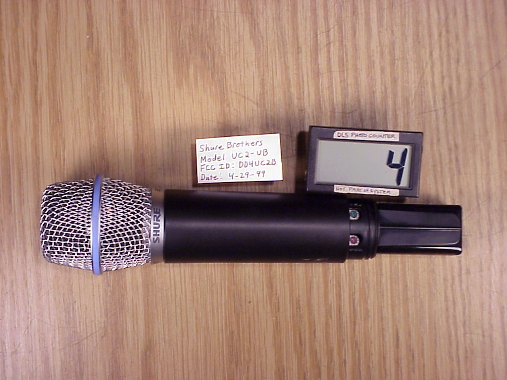
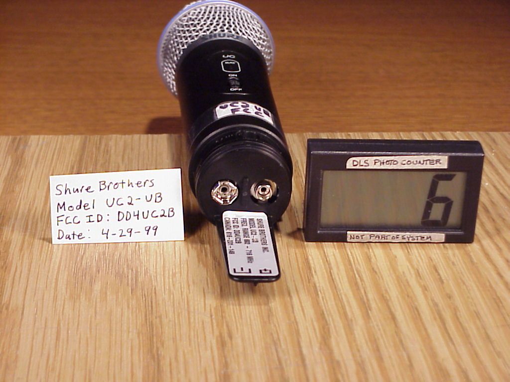
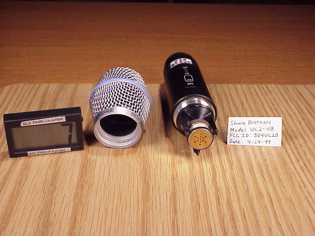
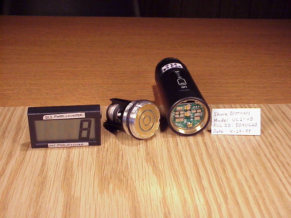
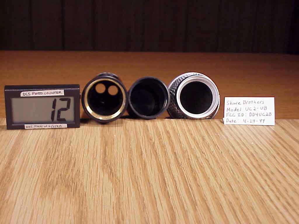
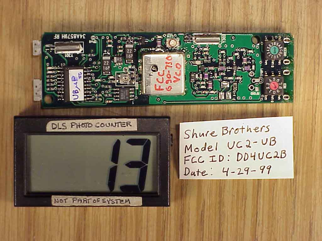
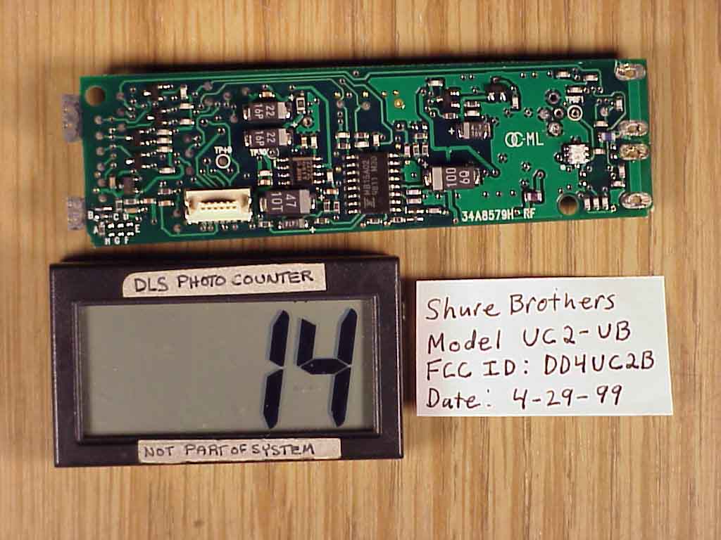
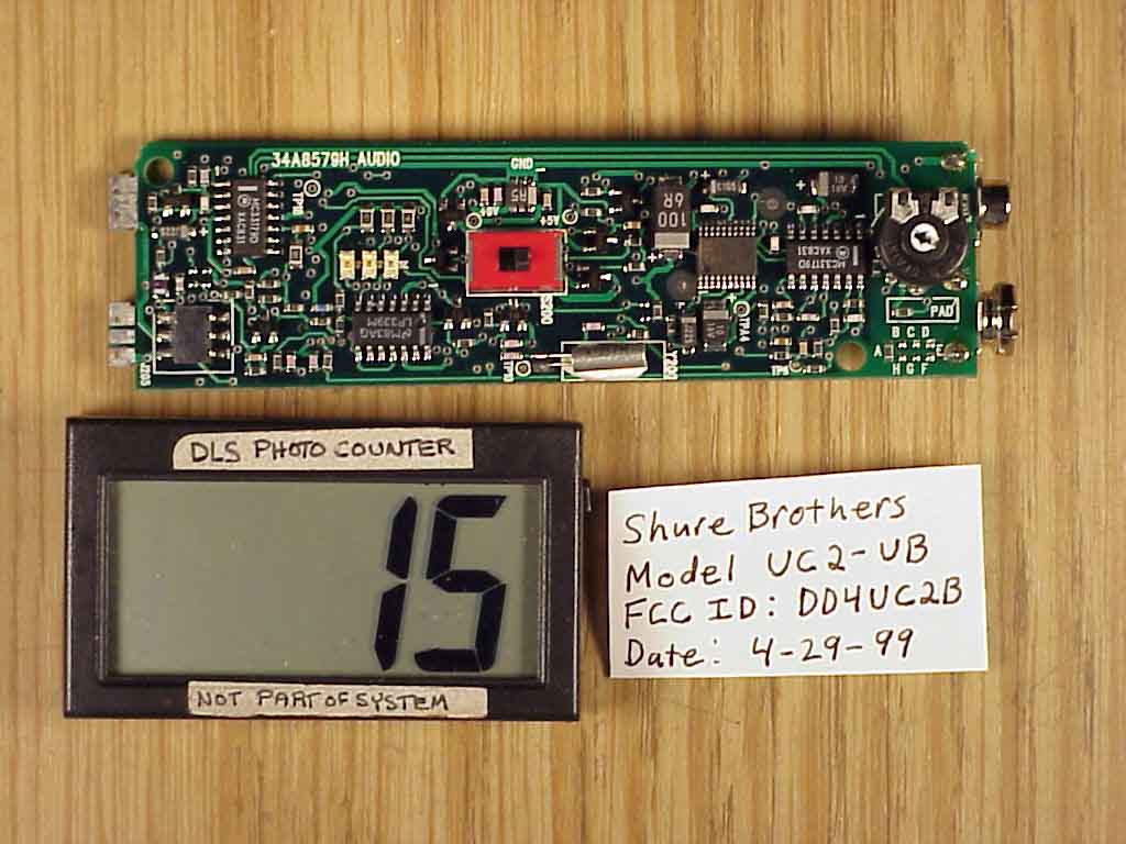
Document Text
Text extracted from the exhibit documents filed with the FCC. Open a document above to read the original.
Users Manual
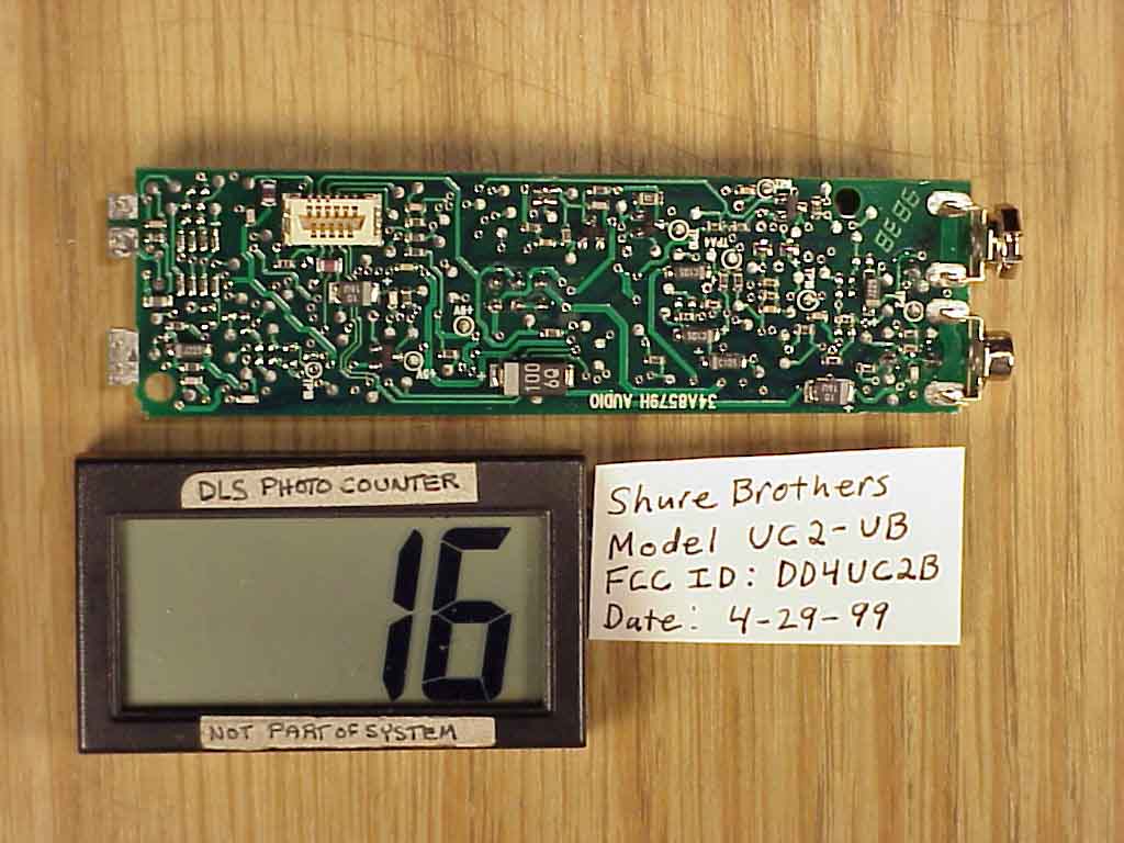
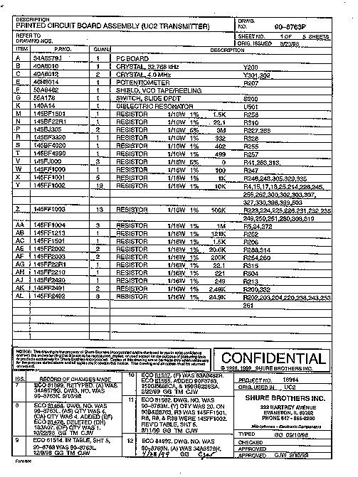
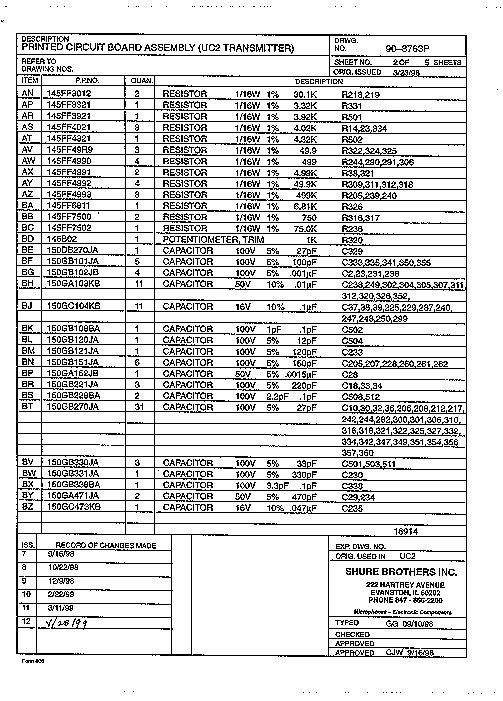
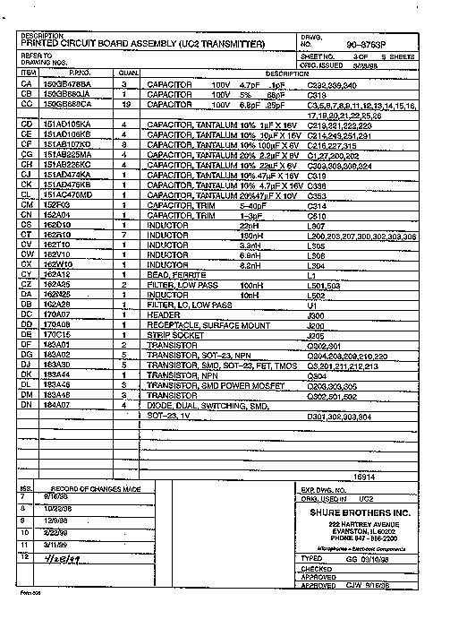
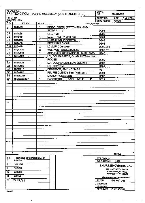
E1998, Shure Brothers Inc.Printed in U.S.A. 25A1044 (RI) Service Manual UC2 Hand-Held UHF Transmitter Characteristics General The Shure UC2 Hand-Held UHF Transmitter is a microprocessor- controlled microphone transmitter, operating in the 774 to 862 MHz frequency range. The UC2 hand-held transmitter is used in mid-level installed sound, rental, and concert sound applications. Six frequency range variations are available. Controls and Connectors 1. Mic Cartridge Grille (87 shown) 2. Battery Fuel Gauge LEDs 3. Power ON/OFF Switch 4. Audio Gain Control 5. 9 V Battery 6. Battery Cup 7. Group Selection Rotary Switch 8. Channel Selection Rotary Switch Figure 1.UC2 Controls and Connectors 1 2 3 48 7 5 6 Service Note: Shure recommends that all service procedures be performed by a Factory-Authorized Service Center or that the product be returned directly to Shure Brothers Inc. Shure UC2 Hand-Held UHF Transmitter 2 Characteristics 25A1044 (RI) Circuit Description CONTROL PLL CONTROL MCU EEPROM (MEM) PWR. OFF DETECT +5V REG. GROUPCHANNEL SYNTH. RF POWER RF MUTERF MUTE VCO FROM BATT. UNREG. PWR. +5v AUDIO IN PWR. HOLD CIRCUIT ON / OFF SWITCH FET BYPASS TONE KEY CIRCUIT Σ TONE CONTROL TONE KEY CALL ID BATTERY MGMT. & FUEL GAUGE AUDIO OUT LIMITER CONTROL OUTPUT LIMITER CONTROL INPUT MIC Figure 2.UC2 Hand-Held Transmitter Circuit Block Diagram 32.768 kHz 4 MHz 4 MHz MB15A02 MC68HC705 Audio Section FCC-Approved Audio enters L200, an inductor used as an rf choke. The signal is ac coupled through capacitor C200 into a user adjustable gain stage. Resistors R202 and R203 set up a half-supply bias, and R204 sets the input impedance for the stage. The back-to-back diodes, D201, are used to keep the op-amp from snapping to the rail and reverse phasing when the maximum input volt- age range is exceeded. The 30 dB adjustable gain stage is built around U200A. The user externally controls the gain of this stage. C206, C207, and C208 protect Shure UC2 Hand-Held UHF Transmitter Characteristics325A1044 (RI) the amplifier and bias circuits from rf interference. Due to its topology, this stage is unique because it is non-inverting and allows for a gain less than unity. Audio then enters a buffer to the pre-emphasis network and the compression stage. R213, R214, and C211 set up two corners for the pre-emphasis network. The pre-emphasis boosts the high frequencies before transmission. This network feeds an NE575 compander, U202, that utilizes an external amplifier, U201B. The compander performs a 2:1 logarithmic compression of the audio signal. The pre-emphasis network also plays a role in setting the hinge point (0 dB gain) of the compander. From the compressor, the processed audio enters a low-pass filter, U201D, and then a summing amplifier, U201C. The tone key (and for J frequencies, the call ID signal) is added here to the processed audio signal. Transistors Q208 and Q209, with crystal Y200, form the tone key oscillator circuit to provide a stable, continuous 32.768 kHz sine wave. Transistor Q210 buffers the tone key signal before it is added to the audio signal. The tone key signal is used in the receiver to provide audio output only when the tone key signal is present with the transmitted signal. If the tone key or the transmitter is turned off, the receiver will be muted. The tone key squelch eliminates receiver noise associated with loss of a carrier. Q211 acts as a switch for toggling the tone key MUTE/ UNMUTE ; it is controlled via the microprocessor. The tone key signal, along with the processed audio signal, is then fed to a summing amplifier, U201C. R244, at the output of the summing amplifier, helps prevent spurious oscillations from the op-amp. After passing the ac coupling capacitor, C243, the signal is fed to the rf module via the rf choke, L207. The battery meter circuit is comprised of U205; LEDs D203, D204, D205; and various resistors. The meter works by comparing a divided down version of the battery voltage (R250, R251) to two thresholds (set by R252, R253, and R254), and lighting the appropriate LED. A 9 Vdc battery provides power to the audio printed circuit board (pcb), via switch S200. FET Q203 provides electrical reverse battery protection by connecting the negative battery terminal to the pcb ground only when the battery is connected with the correct polarity. The 9 Vdc then enters U203, a low dropout 5 V regulator, which gives a clean, regulated 5 V supply to run the audio circuitry. The regulator has appropriate bypass capacitors on its input and output. Q201, Q202, Q212, Q213, and their respective resistors, provide power management and timing. Shure UC2 Hand-Held UHF Transmitter 4 Characteristics 25A1044 (RI) ETSI-Approved This transmitter uses the same pcb as the domestic system, but it requires a different topology and different parts. A limiter is inserted between the pre-emphasis and the compressor to limit the occupied bandwidth. The buffer after the gain stage, U201A, is now an inverter with pre-emphasis and 20 dB of attenuation. Previously bypassed, the expander side of the NE575 (U202) is now activated and used as a limiter. A sample of the audio is taken from the limiter output, U202, pin 6, and sent to a control circuit that detects signals above a limiting threshold. The comparator then sends a control signal to U202, pin 5, which clamps the signal. Rf Section Processed audio enters R320, an internal potentiometer that is adjusted for 45 kHz deviation (40 kHz for England), 100% modulation, with a 6.8 dBu 1 kHz tone at the output of the compressor. For J fre- quencies, R320 is adjusted for 5 kHz deviation with 1 kHz tone injected into the mic input, to give –23.47 dBu at U201, pin 7 (TPA4). The audio is then fed to the tuning voltage pin of the voltage con- trolled oscillator ( VCO), which modulates the carrier directly. A phase locked-loop ( PLL) frequency-synthesized system eliminates the need for multiplier stages and results in a much higher degree of spectral purity. The VC…
Text truncated - open the document above for the full version.
Block Diagram
CONTROL PLL CONTROL MCU EEPROM (MEM) PWR. OFF DETECT +5V REG. GROUPCHANNEL SYNTH. RF POWER RF MUTERF MUTE VCO FROM BATT. UNREG. PWR. +5v AUDIO IN PWR. HOLD CIRCUIT ON / OFF SWITCH FET BYPASS TONE KEY CIRCUIT Σ TONE CONTROL TONE KEY CALL ID BATTERY MGMT. & FUEL GAUGE AUDIO OUT LIMITER CONTROL OUTPUT LIMITER CONTROL INPUT MIC Fig. 1 Block Diagram of the Hand Held Transmitter
Operational Description
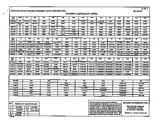
Description: UC2 Hand-Held UHF Transmitter with SM58, Beta 58 , SM87, or Beta 87. DRWG. UC2-7 (97-480, 97-481, 98-415, 98-416) Refer To Drawing NOS. 6A250, 90-8763-11, 90-8763-3, 34-8579, 900G000 Page 1 of 19 ISS RECORD OF CHANGES MADE 1. Production Release 2ECO 81440: Revised thru-out for typos. No spec changes 3ECO 81498: Added MC and MD specifications EXP. DWG. NO. 16914 SHURE BROTHERS INC. 222 HARTREY AVENUE EVANSTON, IL 60202 PHONE 847-866-2200 Microphones-Electronic Components TYPED S. Grad, D.Cerra, I. Singh CHECKED APPROVED K. Mikes APPROVED Shure Model UC2B (58, 87, B58, B87) UHF Handheld Transmitter Specification Outline General Product Description I Special Features II Circuit Description III Test Equipment IV Alignment Procedure V Test for Product Acceptance VI Agency Approvals VII Additional Product Specifications VIII Mechanical Specification IX Environmental Specification X Service Evaluation General Product Description The Shure Model UC2 is a UHF,μP (microprocessor) controlled, transmitter operating over the Domestic frequency range of 692 to 716 MHz (With four different models). The transmitter features adjustable groups/channels, a battery status indicator, a plastic enclosure, and utilizes an internal antenna to provide optimum range. This product is intended for use in installed sound, music instrument,audio/video, audio rental, and touring sound markets. ISpecial Features 1. Frequency agility, microprocessor controlled. User capable of selecting 10 groups of 16 compatible channels each, within the 782-806 MHz frequency band. This allows for a maximum of 160 selectable frequencies. There are 6 different models available from 692-716 MHz. 2. A minimum of 12 compatible systems (Country dependent). 3. Tone-key squelch. 4. Electrical reverse battery protection. 5. Supports SM58, SM87, BETA58A, and BETA87 cartridges. 6. 8 hour minimum battery life for a new 9V alkaline battery. 7. Rugged, plastic construction. 8. Power On/Off two position miniature switch located on the handle bezel. 9. Group/Channel rotary switches located on handle under the cup. 10. Three LED battery fuel gauge. Description: UC2 Hand-Held UHF Transmitter with SM58, Beta 58 , SM87, or Beta 87. DRWG. UC2-7 (97-480, 97-481, 98-415, 98-416) Refer To Drawing NOS. 6A250, 90-8763-11, 90-8763-3, 34-8579, 900G000 Page 2 of 19 ISS RECORD OF CHANGES MADE 1. Production Release 2ECO 81440: Revised thru-out for typos. No spec changes 3ECO 81498: Added MC and MD specifications EXP. DWG. NO. 16914 SHURE BROTHERS INC. 222 HARTREY AVENUE EVANSTON, IL 60202 PHONE 847-866-2200 Microphones-Electronic Components TYPED S. Grad, D.Cerra, I. Singh CHECKED APPROVED K. Mikes APPROVED 11. “Greenie” screwdriver adjustable audio gain. IICircuit Description Audio Section Audio enters L200, an inductor used as an RF choke. The signal is ac coupled through C200 into a user adjustable gain stage. R202 and R203 set up a half- supply bias and R204 sets the input impedance for the stage. The back to back diodes, D201, are used to keep the op amp from snapping to the rail and reverse phasing, when the maximum input voltage range is exceeded. The 32dB adjustable gain stage is built around U200A. The gain of this stage is externally controlled by the user. C206, C207, and C208 protect the amplifier and bias circuits from RF interference. This is a unique stage in that it is non-inverting, and allows for a gain less than unity. Audio then enters a buffer to the premphasis network and the compression stage. R213, R214, and C211 set up two corners for the premphasis network. The purpose of pre-emphasis is to boost the high frequencies before transmission. This network feeds an NE575 compandor, U202, which utilizes an external amplifier U201B. The compandor performs 2:1 logarithmic compression of the audio signal. Additionally, the pre-emphasis network plays a role in setting the hinge point (0dB gain) of the compandor. From the compressor, the processed audio enters a summing amplifier U201C. Here, tone key (and the call ID signal for the JB Group) is added to the processed audio signal. Transistors Q208 and Q209 with crystal Y200 form the tone key oscillator circuit which provides a stable continuous 32.768 kHz sine wave. Transistor Q210 buffers the tone key signal before it is added to the audio signal. The tone key signal is used in the receiver to provide audio output only when the tone key signal is present with the transmitted signal; therefore, if the tone key or the transmitter is turned off, the receiver will be muted. The tone key squelch will eliminate receiver noise associated with loss of a carrier. Q211 acts as a switch for toggling the tone key MUTE/UNMUTE and is controlled by the μP. The tone key signal along with the processed audio signal is then fed to a summing amplifier U201C. R244, at the output of the summing amplifier, is used to help prevent spurious oscillations from the opamp. After passing the ac coupling capacitor, C243, the signal is then fed to the RF module through an RF choke, L207. The battery meter circuit is made up of comparator U205, LED’s D203, D204, D205, and various resistors. The meter works by comparing a divided down version of the battery voltage (R250, R251) to two thresholds (set by R252, R253, and R254), and lighting the appropriate LED. Description: UC2 Hand-Held UHF Transmitter with SM58, Beta 58 , SM87, or Beta 87. DRWG. UC2-7 (97-480, 97-481, 98-415, 98-416) Refer To Drawing NOS. 6A250, 90-8763-11, 90-8763-3, 34-8579, 900G000 Page 3 of 19 ISS RECORD OF CHANGES MADE 1. Production Release 2ECO 81440: Revised thru-out for typos. No spec changes 3ECO 81498: Added MC and MD specifications EXP. DWG. NO. 16914 SHURE BROTHERS INC. 222 HARTREY AVENUE EVANSTON, IL 60202 PHONE 847-866-2200 Microphones-Electronic Components TYPED S. Grad, D.Cerra, I. Singh CHECKED APPROVED K. Mikes APPROVED Power to the audio pcb comes from a 9V battery, via switch S200. FET Q203 is used for electrical reverse battery pro…
Text truncated - open the document above for the full version.
Operational Description
CONTENTS SPECIFICATIONS2. . . . . . . . . . . . . . . . . . . . . . . . . . . . . . . . . . . . . . . . . . . . . . . . Furnished Accessories4. . . . . . . . . . . . . . . . . . . . . . . . . . . . . . . . . . . . . . . . . Optional Accessories5. . . . . . . . . . . . . . . . . . . . . . . . . . . . . . . . . . . . . . . . . . . Replacement Parts5. . . . . . . . . . . . . . . . . . . . . . . . . . . . . . . . . . . . . . . . . . . . . FREQUENCY SELECTION GUIDE6. . . . . . . . . . . . . . . . . . . . . . . . . . . . . . . . . . Compatibility Groups6. . . . . . . . . . . . . . . . . . . . . . . . . . . . . . . . . . . . . . . . . . . Shure Brothers Incorporated 222 Hartrey Avenue Evanston IL 60202-3696 U.S.A. UHF Wireless System USER GUIDE SUPPLEMENTUB (692–716 MHz) 27A8694 (SE) E1999, Shure Brothers Incorporated Printed in U.S.A. 2 SPECIFICATIONS RF Carrier Frequency Range 692–716 MHz Working Range 152.4 m (500 ft), minimum, under typical conditions; 487.6 m (1600 ft ) line of sight NOTE: Actual working range depends on RF signal absorption, reflection and interference Audio Frequency Response 45 to 15,000 Hz, ±2 dB. NOTE: Overall system frequency response depends on the microphone element Gain Adjustment Range UC1B: –6 to 34 dB UC2B: –6 to 26 dB Modulation ±45kHz deviation compressor-expander system with pre-and de-emphasis RF Power Output UC1B: 50 mW effective radiated power, typical UC2B: 20 mW effective radiated power, typical Dynamic Range >100 dB, A-weighted Receiver Audio Output Level (Maximum) +5 dBu typical, unbalanced output +14 dBu typical, balanced output RF Sensitivity UC4B: –108 dBm at 12 dB SINAD Image Rejection 90 dB typical Spurious Rejection 70 dB typical Ultimate Quieting (ref. 45 kHz deviation) >100 dB, A-weighted Audio Polarity Positive pressure on microphone diaphragm (or positive voltage applied to tip of WA302 phone plug) produces positive voltage on pin 2 with respect to pin 3 of low impedance output and the tip of the high impedance 1 / 4 -inch output System Distortion (ref. ±45 kHz deviation, 1 kHz modulation) 0.4% Total Harmonic Distortion typical Power Requirements UC1B, UC2B: 9V alkaline battery (Duracell MN1604 recommended); Nicad optional UC4B: 15 Vdc , 600 mA 50/60 Hz Power Consumption: 600 mA x 15 V, maximum Transmitter Battery Life (Typical) 8 hours (with Duracell MN1604 9V alkaline battery) Operating Temperature Range -7° to 49° C (20° to 120° F) NOTE: Battery characteristics may limit this range Overall Dimensions UC1B: 99.06 mm L x 63.50 mm W x 22.86 mm D (3–29/32 L x 2–1/2 W x 29/32 in. D) UC2B/58:247.30 mm L x 50.8 mm Dia. (9–1/2 L x 2 in. Dia.) UC2B/BETA 58: 241.30 mm L x 50.80 mm Dia. (9–1/2 L x 2 in. Dia.) UC2B/87:215.90 mm x 50.80 mm Dia. (8–1/2 L x 2 in. Dia.) UC2B/BETA 87: 215.90 mm L x 50.8 mm Dia. (8–1/2 L x 2 in. Dia.) UC4B: 44.50 mm H x 197.40 mm W x 214.30 mm D (1–3/4 L x 7.77 W x 8.44 in. D) 3 Net Weight UC1B: 73.50 g (2.59 oz.) without battery UC2B/58, U2/BETA 58: 311.9 g (11 oz.) without battery UC2B/87, U2/BETA 87: 198.5 g (7 oz.) without battery UC4B: 1.22 kg (2 lbs, 11 oz.) Certification UC1B, UC2B: Type Accepted under FCC Parts 74. Certified by IC in Canada under TRC-78. FCC ID for UC1B: DD4UC1B. FCC ID for UC2B: DD4UC2B. UC4B: UL and cUL Listed to UL 813 and CSA C22.2 No. 1. VDE Certified to EN 60 950. Approved under the Notification provision of FCC Part 15; Certified by IC in Canada under TRC-78. FCC ID: DD4UC4B. UC1B Transmitter Input (Figure 1) Connector: Switchcraft TA4F Tini Q.G. or LEMO connector (optional) Input Configuration: Unbalanced, active Actual Impedance: 18 kΩ with lavalier microphone 1 MΩ with instrument cable Maximum Input Level: 9 Vp–p (10 dBV) for 1% THD at minimum gain setting using 1 kHz signal. TA4F Tini Q.G. Connector Pin Assignments: Pin 1: Tied to Ground Pin 2: Tied to +5 V Pin 3: Tied to Audio Pin 4: Tied thru 20kΩ Resistor to Ground. (On instrument adapter cable, Pin 4 floats) LEMO Connector Pin Assignments: Pin 1: Tied to Pin 3 and 10 kΩ to Ground Pin 2: +5V Pin 3: Tied to Pin 1 Pin 4: Tied to Shield (Ground for Positive Bias) Voltage for Remote Power: +5 V supplied to microphone cartridge 27 pF 20K Ω 27 pF +5 V AUDIO GROUND UC1B MIC JACK BOARD 2 1 4 500 Ω 500 Ω MICROPHONE ELEMENT 3 2 1 3 4 NOTE: LAVALIER MIC TIES PINS 3 AND 4 TOGETHER; GUITAR CABLE DOES NOT. 27 pF 499 Ω 499 Ω 3 27 pF 10K Ω AUDIO SHIELD 1 4 2 BIAS UC1B UC1BL (LEMO 4 PIN) MIC JACK BOARD FIGURE 1 4 UC1B Transmitter Output Antenna: Flexible 1/4 wave wire Actual Impedance: 50 Ω Nominal Output Level: +16 dBm Maximum Output Level: +17 dBm UC2B Transmitter Input Input Configuration:Unbalanced, active Actual Impedance: 25 kΩ Maximum Input Level:9 Vp–p (10 dBV) for 1% THD at minimum gain setting using 1 kHz signal. UC2B Transmitter Output Antenna: Internal dipole Actual Impedance: 50 Ω Nominal Output Level: +12 dBm, radiated Maximum Output Level: +12 dBm, conducted UC4B Receiver Input Connector:AntennaPower Input Connector Type:BNCdc style Actual Impedance:50 Ω–– Nominal Input Level:–95 to –30 dBm15 Vdc Maximum Input Level:+6 dBm (–20 dBm recommended) 17 Vdc Pin Assignments:Shell = Ground Center = Signal Center pin positive UC4B Receiver Output Connector:High Z AudioLow Z Audio Output Configuration: UnbalancedBalanced Actual Impedance: 1 kΩ44Ω Nominal Input Level: –––– Output Level: 5 dBu maximum14 dBu maximum Pin Assignments: Tip = Hot Ring/ Sleeve = Gnd 1 = Ground 2 = Hot 3 = Hot FURNISHED ACCESSORIES Microphone Stand Adapter (UC2B)WA370A. . . . . . . . . . . . . . . . . . . . . . . . . . . . . . . . . . . . Zipper Bag (UC1B)26A13. . . . . . . . . . . . . . . . . . . . . . . . . . . . . . . . . . . . . . . . . . . . . . . . . . . Zipper Bag (UC2B)26A14. . . . . . . . . . . . . . . . . . . . . . . . . . . . . . . . . . . . . . . . . . . . . . . . . . . Screwdriver 80A498. . . . . . . . . . . . . . . . . . . . . . . . . . . . . . . . . . . . . . . . . . . . . . . . . . . . . . . . 1/4 Wave AntennaUA400. . . . . . . . . . . . . . . . . . . . . …
Text truncated - open the document above for the full version.
Test Report
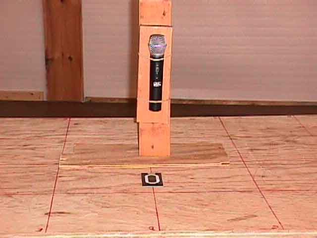
EMC Test ServicesReport No. 7354 1250 Peterson Drive, Wheeling, Illinois 60090, USA07/27/99 Page 1 TEST SPECIFICATION: FCC "Rules and Regulations", Part 74, Experimental Radio, Auxiliary, Special Broadcast and Other Program Distribution Services for Operation in the 614 to 806 MHz Band Subpart H, Low Power Auxiliary Stations Sections 74.801 to 74.882 THE FOLLOWING MEETS THE ABOVE TEST SPECIFICATION Formal Name:UC Wireless Series Transmitter Kind of Equipment:Wireless Microphone (Hand-held) Test Configuration:Transmitting (modulated carrier) Emission Designator: 120KF3B Transmitter FCC ID: DD4UC2B Model Number: UC2B Serial Number: NA Dates of Test:April 28, 29 & May 4, 1999 Test Conducted for:Shure Brothers, Inc. 222 Hartrey Avenue Evanston, Illinois 60202 NOTICE:Please see change information listed inside of this report. This report must not be used by the customer to claim product endorsement by NVLAP or any agency of the United States Government, and it cannot be reproduced (except in full), without the approval of D.L.S. Electronic Systems Inc. EMC Test ServicesReport No. 7354 1250 Peterson Drive, Wheeling, Illinois 60090, USA07/27/99 Page 2 SIGNATURE PAGE Report Written By: Arnom C. Rowe Test Engineer EMC-001375-NE Report Reviewed by: Jack Prawica Lab Manager Report Approved by: Brian J. Mattson General Manager Company Official: Shure Brothers, Inc. Page 3 NVLAP Certificate of Accreditation (Available upon request) Page 4 NVLAP Scope of Accreditation (Available upon request) EMC Test ServicesReport No. 7354 1250 Peterson Drive, Wheeling, Illinois 60090, USA07/27/99 Page 5 1.Cover Pagei 2.Signature Pageii 3.NBS Certificate of Accreditationiii 5.Table of Contentsiv 7.Summary of Test Report1.0 7.Introduction2.0 7.Object3.0 7.Test Set-up4.0 8.Test Equipment (Bandwidths and Detector Function)5.0 8.RF Power Output6.0 9.Graphs taken of the RF Power Output Measurements6.0 12Modulation Characteristics7.0 13.Graphs taken of the Modulation Characteristics7.0 14.Occupied Bandwidth8.0 15.Graphs taken of the Occupied Bandwidth8.0 25.Frequency Deviation9.0 26.Graphs taken of the Frequency Deviation9.0 27.Spurious Emission Measurements at Antenna Terminals10.0 28.Conducted Emission Data taken10.0 29.Conducted Emission Graphs Taken10.0 EMC Test ServicesReport No. 7354 1250 Peterson Drive, Wheeling, Illinois 60090, USA07/27/99 Page 6 30.Field Strength of Spurious Emission Measurements11.0 32.Radiated Data taken for Field Strength Measurements11.0 37.Radiated Graphs taken for Field Strength Measurements11.0 44.Frequency Stability (Temperature)12.0 45.Graphs taken of Frequency Stability (Temperature)12.0 51.Frequency Stability (Voltage Variation)13.0 52.Photo Information and Test Set-Up14.0 53.Photos Taken During Testing15.0 55.Change Information16.0 57.Results of Tests17.0 57.Conclusion18.0 58.Equipment ListTABLE 1 EMC Test ServicesReport No. 7354 1250 Peterson Drive, Wheeling, Illinois 60090, USA07/27/99 Page 7 1.0SUMMARY OF TEST REPORT It was found that the UC Wireless Series Transmitter S/N NA meets the radio interference emission requirements of the FCC "Rules and Regulations", Part 74, Subpart H, Sections 74.801 to 74.882 for Low Power Auxiliary Stations operating in the 692 to 716 MHz Frequency Band. 2.0INTRODUCTION On April 28, 29 & May 4, 1999, a series of radio frequency interference measurements were performed on Wireless Microphone (Hand-held), S/N NA. The tests were performed according to the procedures of FCC as stated in Part 2 Subpart J, Equipment Authorization Procedures of the Code of Federal Regulations 47, by personnel of D.L.S. Electronic Systems, Inc. who are responsible to Donald L. Sweeney, Senior EMC Engineer. 3.0OBJECT The purpose of this series of tests was to determine if the test sample could meet the radio frequency emission requirements of the FCC "Rules and Regulations", Part 74, Subpart H, Sections 74.801 to 74.882 for Low Power Auxiliary Stations operating in the 692 to 716 MHz Frequency Band. 4.0TEST SET-UP All radiated emission tests were performed at D.L.S. Electronic Systems, Inc. The radiated tests were made with the test item placed on a wooden turntable located in the Test Room with the receive antenna placed at one or three meters from the device under test. EMC Test ServicesReport No. 7354 1250 Peterson Drive, Wheeling, Illinois 60090, USA07/27/99 Page 8 5.0TEST EQUIPMENT (Bandwidths and Detector Function) All data was automatically plotted using peak detector function. This information was then used to determine the frequencies of maximum emissions. Manual measurements were perform on those frequencies using a peak detector function of the Analyzer with the bandwidths specified by the FCC. From 200 MHz to 1000 MHz a bandwidth of 100 kHz was used (except for Occupied Bandwidth), and above 1000 MHz, wide enough bandwidths were used, depending upon the test being made, to ensure proper measurement of the narrowband signal. A list of the equipment used can be found in Table 1. All equipment was calibrated per the instruction manuals supplied by the manufacturer. 6.0RF POWER OUTPUT - PART 2.1046 As stated in PART 74.861 (e-1), the output power should not exceed 250 milliwatts (24 dBm). The UC Wireless Series Transmitter was tuned according to the tune-up procedures specified in Part 2.1033 (c-8), and adjusted for its maximum output power. The RF output power was measured in the open field, using the following test method: Substitution Method: The radiated signal from the EUT was measured. The EUT was then substituted with a signal generator and a tuned dipole antenna. The output of the signal generator was increased until the level received by the tuned dipole equaled that of the previous measurement from the EUT. Measurement made: 119 dBuV which equals 0.0159 watts MARGIN: 0.25 watts - 0.0159 watts = 0.234 watts NOTE: See the following pages for the graphs of the actual measurements made: EMC Test ServicesReport No. 7354 1250 Peterson Drive, Wheeling, Illinois 600…
Text truncated - open the document above for the full version.
Test Report
October 4, 1999 Mr. George Tannahill FCC Application Processing Branch Re: FCC ID DD4UC2B Correspondence Reference Number: 9870 731 Confirmation Number: EA94794 Date of Original E-mail: 09/29/1999 Dear Mr. Tannahill, With respect to the questions you raised in your E-mail message of the above date: 1. The occupied bandwidth plots were obtained by following the procedure detailed below, which was previously recommended by your office: First, the modulation frequency of maximum response was established by supplying an audio signal to the transmitter input, at a level well below the onset of limiting, and varying its frequency over the entire audio range until the point was found where maximum deviation occurs. Then, the audio signal was adjusted so as to produce 50% modulation (22.5 kHz deviation, in the case of the UC2B) on a Boonton Model 8200 modulation analyzer, and the audio input level was recorded. Next the audio frequency was changed to 2500 Hz, and the input level was increased by 16 dB over that which was recorded at the frequency of maximum response. A plot was then made of the resulting emission. In addition, several other plots were made at other representative modulation frequencies, using the same input level, so as to demonstrate the transmitter’s modulation characteristics. A reference plot was also made with no audio modulation applied. Note that this transmitter incorporates a 32.768 kHz continuous pilot (control) signal (referred to by Shure as “Tone Key”). Note also, that the Boonton modulation analyzer employs a broadband demodulator. Thus, the deviation of the pilot signal affects the setting of the 50% modulation point. This is probably why the modulation plots appear to be undermodulated. A percentage of the deviation is due to the pilot signal. It is possible to perform the procedure in such a way that the modulation due to the pilot signal is ignored in determining the audio input level for 22.5 kHz deviation. To demonstrate this, the above procedure was repeated with the pilot signal temporarily disabled while the audio input level for 22.5 kHz deviation was being determined. A second series of plots showing the resulting emissions have been provided with this attachment. All occupied bandwidth plots were made with the pilot signal re-enabled, with the exception of one reference plot which was made with the pilot signal disabled and no audio input. You will observe that although larger than in the previous set of plots which were included in the original submission, in no case does the occupied bandwidth of the MICROPHONES AND ELECTRONIC COMPONENTS Shure Brothers Incorporated 222 Hartrey Avenue Evanston, IL 60202-3696 • U.S.A. emission exceed the specified limits. Again, the difference is due to the inclusion or exclusion of the pilot signal in setting up the reference audio input level for 50% modulation (22.5 kHz deviation). 2. The modulation limiting plot was intended to demonstrate the transmitter’s modulation characteristics at input levels up to, and beyond input levels for normal operation. From the occupied bandwidth plots, you will note that the audio input level for 16 dB above 50% modulation at the frequency of peak response is –60 dBV, (or –55.5 dBV if deviation due to the pilot signal is disregarded). The peak deviation is dependent upon the modulation frequency due to pre-emphasis; however it would be close to 40 kHz at the frequency of maximum response if the pilot signal is included in determining the input level for the occupied bandwidth. Shure uses 45 kHz as the nominal 100% modulation point. 3. There was a typographical error in the specification of the emission designator. According to Section 2.201 of the Commission’s Rules, F3E would designate Frequency Modulation, a single channel containing analogue information, and telephony or sound broadcasting. You have indicated that you feel this may be the most appropriate. Another possible designator would be FXW, due to the inclusion of the continuous 32.768 pilot signal which is used by the receiver for telemetry and control. The designator FXW indicates Frequency Modulation, cases not covered, and a combination of modulation types (in this case, telephony or sound broadcasting and telemetry). We will accept whatever designator you would prefer. We trust that the above information will be helpful to you. If you have any further questions, please do not hesitate to contact us. Sincerely, Edgar C. Reihl, P.E. Principal Engineer Shure Brothers Incorporated Telephone: (847) 866-2289 E-mail: [email protected] UC2B Modulation vs Frequency for 10mV RMS Input 0 5 10 15 20 25 30 35 40 45 50 55 60 65 70 75 50Hz 100Hz 250Hz 500Hz 1kHz2kHz4kHz6kHz8kHz 10kHz 15kHz 20kHz Frequency Deviation kHz UC2B Input Level Vs Deviation 0 5 10 15 20 25 30 35 40 45 50 55 60 65 70 75 80 -80-70-60-50-40 Input Level dBV +/-kHz Deviation 80Hz 500Hz 2.5kHz 10kHz 15kHz Mr. George Tannahill FCC Application Processing Branch FCC ID DD4UC1B Correspondence Reference Number: 9790 731 Confirmation Number: EA94793 Date of Original E-mail: 9/23/99 Dear Mr. Tannahill, With respect to the questions you raised in your E-mail message of the above date: Please provide an ERP relative to a dipole power output measurement and show all measured values and calculations. Page 31 (field strength) is updated and included with this letter. The emission designator requested is F3B. Based on the rest of the report it appears F3E is more appropriate. Please justify the requested designator. The correct emission designator is F3E. This was an error made when doing the data entry. Arnom…
Text truncated - open the document above for the full version.
Contact Information
Applicant
Craig Kozokar(EMC Project Engineer)
Technical Contact
DLS Electronic Systems, Inc.Arnom (Arnie) C Rowe
[email protected]847-537-6400
1250 Peterson Drive · Wheeling, Illinois · United States
Test Firm
DLS Electronic Systems, Inc.Donald Sweeney
847-537-6400
Technical Specifications
| # | Rule Parts | Frequency Range | Power Output | Emission | Tolerance |
|---|---|---|---|---|---|
| 1 | 74.861 | 692 MHz - 716 MHz | 20.00 mW | 130KF3E | 0.0050000000 % |
Other Applications from Shure Incorporated
DD4IMXBP
Dec 24, 2025UC Wall
Equipment Class
NII - Unlicensed National Information Infrastructure TXDD4SLXD3EG57
Jul 25, 2025Plug-on Wireless Transmitter
Equipment Class
DTS - Digital Transmission System
DD4ULXD8G50
Sep 18, 2024Wireless Gooseneck Transmitter
Equipment Class
DWM - Part 15 Wireless Microphone
DD4ULXD8H50
Sep 18, 2024Wireless Gooseneck Transmitter
Equipment Class
DWM - Part 15 Wireless Microphone
DD4ULXD6G50
Sep 08, 2024Wireless Boundary Transmitter
Equipment Class
TLD - Licensed LPAS Device