DD4ULXD1L50Wireless Microphone Transmitter
Shure Incorporated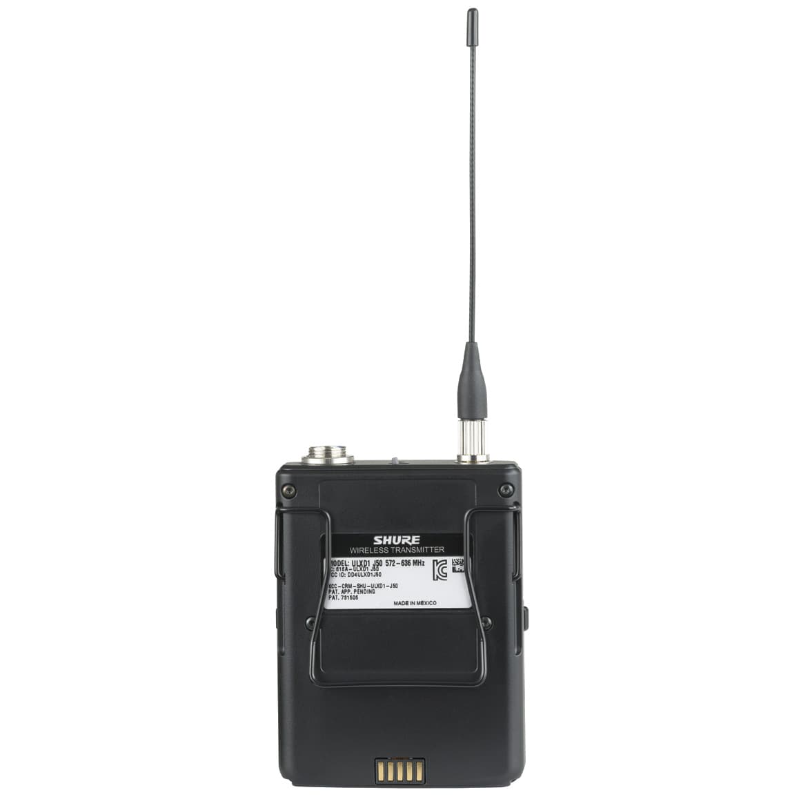
Click to zoom
Application Details
- Equipment Class
- TNT - Licensed Non-Broadcast Transmitter Worn on Body
- Date of Grant
- Dec 07, 2011
- Application Purpose
- Original Equipment
- Date of Application
- Dec 07, 2011
- Equipment Note
- Wireless Microphone Transmitter
- Frequency Range
- 632.00000000 - 696.00000000
- Company
- Shure Incorporated
- Country
- United States
Documents & Files
Document Text
Text extracted from the exhibit documents filed with the FCC. Open a document above to read the original.
Users Manual
1 ©2011 Shure Incorporated xxxxxxx (Rev. 1) ULXD Digital Wireless System Draft 9/14/11 3 READ these instructions.1. KEEP these instructions.2. HEED all warnings.3. FOLLOW all instructions.4. DO NOT use this apparatus near water.5. CLEAN ONLY with dry cloth.6. DO NOT block any ventilation openings. Install in accordance with 7. the manufacturer’s instructions. DO NOT install near any heat sources such as radiators, heat 8. registers, stoves, or other apparatus (including amplifiers) that produce heat. DO NOT defeat the safety purpose of the polarized or grounding-9. type plug. A polarized plug has two blades with one wider than the other. A grounding type plug has two blades and a third grounding prong. The wider blade or the third prong are provided for your safety. If the provided plug does not fit into your outlet, consult an electrician for replacement of the obsolete outlet. PROTECT the power cord from being walked on or pinched, 10. particularly at plugs, convenience receptacles, and the point where they exit from the apparatus. ONLY USE attachments/accessories specified by the 11. manufacturer. 12. UNPLUG this apparatus during lightning storms or when unused 13. for long periods of time. REFER all servicing to qualified service personnel. Servicing is 14. required when the apparatus has been damaged in any way, such as power supply cord or plug is damaged, liquid has been spilled or objects have fallen into the apparatus, the apparatus has been exposed to rain or moisture, does not operate normally, or has been dropped. DO NOT expose the apparatus to dripping and splashing. DO 15. NOT put objects filled with liquids, such as vases, on the appara- tus. The MAINS plug or an appliance coupler shall remain readily oper-16. able. The airborne noise of the Apparatus does not exceed 70dB (A).17. Apparatus with CLASS I construction shall be connected to a 18. MAINS socket outlet with a protective earthing connection. To reduce the risk of fire or electric shock, do not expose this ap-19. paratus to rain or moisture. Do not attempt to modify this product. Doing so could result in 20. personal injury and/or product failure. IMPORTANT SAFETY INSTRUCTIONS USE only with a cart, stand, tripod, bracket, or table speci- fied by the manufacturer, or sold with the apparatus. When a cart is used, use caution when moving the cart/apparatus combination to avoid injury from tip-over. This symbol indicates that dangerous voltage constituting a risk of electric shock is present within this unit. This symbol indicates that there are important operating and maintenance instructions in the literature accompanying this unit. WARNING: This product contains a chemical known to the State of California to cause cancer and birth defects or other reproductive harm. WARNING • Battery packs may explode or release toxic materials. Risk of fire or burns. Do not open, crush, modify, disassemble, heat above 212°F (100°C), or incinerate • Follow instructions from manufacturer • Never put batteries in mouth. If swallowed, contact your physician or local poison control center • Do not short circuit; may cause burns or catch fire • Do not charge or use battery packs with other than specified Shure products • Dispose of battery packs properly. Check with local vendor for proper disposal of used battery packs WARNING: No user-serviceable parts inside. Refer all servicing to qualified service personnel. Draft 9/14/11 4 General Description Features Digital Audio Receiver-controlled gain Frequency Band Selection More bands Transmitter Presets Send presets to the transmitter over a sync Rechargeability Shure’s lithium ion batteries offer unparalleled reliability and longevity in rechargeable technology. Transmitters offer accurate and instantaneous monitoring of bat- tery life. Networking Each receiver has an RJ-45 port on the back for connecting to other receivers over an Ethernet network. Networking receivers allows you to automatically set channels for all the receivers with a single group scan command. You can also control and monitor all networked receivers through the Shure Wireless Workbench PC software. PLACEHOLDER - COMING FROM MIKE J Furnished Accessories Handheld SystemsBodypack System ULXD4 Digital Wireless Receiver sync push control ENTER EXIT SCAN RF A B OL OL gainpoweraudio All Systems ULXD4S ReceiverPS41 Power Supply 1/2 Wave Antenna (2)2’ BNC Cable (2)BNC Bulkead Adapters (2) Rackmount Kit (1)5’ Ethernet Cable (1) AA Alkaline batteries (2) ULXD2 Handheld Transmitter Microphone Cartridge Microphone ClipULXD1 Bodypack Transmitter • One of the following:WA302 instrument cable • Beta 98H/C instrument microphone • Lavalier microphone (MX150, MX153, WL183, WL184, WL185) • WH30 headworn microphone Draft 9/14/11 6 ULXD4 Digital Wireless Receiver sync push control ENTER EXIT SCAN RF A B OL OL gainpoweraudio 12VOUT 150 mA 12VOUT 150 mA ULXD2ULXD2 mic / linemic / linepowerpowerantenna . Bantenna . Bantenna . Aantenna . A 15V 0.6A inst / auxinst / aux line mic www.shure.com 25 L5 644-800 MHz 2 3 3 4 4 5 5 1 1 1 8 8 9 10 11 6 6 7 7 Front Panel ① Sync Button Press the sync button while the receiver and transmitter IR windows are aligned to transfer settings from the receiver to the transmitter ② Infrared (IR) Sync Window Sends IR signal to the transmitter for sync ③ Network Icon Illuminates when the receiver is connected with other Shure devices on the network. IP Address must be valid to enable networked control ④ Encryption Icon Illuminates when AES-256 encryption is activated: Utilities > Encryption ⑤ LCD Display Displays settings and parameters ⑥ Scan Button Press to find the best channel or group ⑦ Menu Navigation Buttons Use to select and navigate through parameter menus Back Panel ① RF Antenna Diversity Input Jack (2) For antenna A and antenna B. ② Power Supply Jack Connect the supplied 15 V DC external power supply ③ Network Speed LED (Amber) • Off = 10 Mbps • On = 100 Mbps ④ Ethernet Port Connect to an Ethernet network…
Text truncated - open the document above for the full version.
Cover Letter(s)
November 22, 2011 Elite Electronic Engineering, Inc. 1516 Centre Circle Downers Grove, Illinois 60515-1082 SUBJECT: REQUEST FOR NON-DISCLOSURE FOR FCC ID: DD4ULXD1L50 To Whom It May Concern: Pursuant to 47 CFR Section 0.459, Shure Incorporated hereby requests non-disclosure and confidential treatment of the following materials submitted in support of FCC certification application for FCC ID # DD4ULXD1L50: a. Schematic Diagrams b. Operational Description c. Block Diagram d. Parts List e. Tune Up Procedure Above materials contain trade secrets, proprietary and technical information which would customarily be guarded from competitors under 47 CFR section 0.457(d)(2). Disclosure or publication of any portion of this company confidential material to other parties could cause substantial competitive harm and provide unjustified benefits for competitors. Shure Incorporated understands that pursuant to 47 CFR section 0.457(d)(1)(ii) disclosure of the applicant and all accompanying documentation will not be made before the date of the grant. Sincerely yours, Craig Kozokar EMC Project Engineer, Global Compliance Shure Incorporated
Cover Letter(s)
November 23, 2011 Elite Electronic Engineering, Inc. 1516 Centre Circle Downers Grove, Illinois 60515-1082 SUBJECT: REQUEST FOR SHORT TERM CONFIDENTIALITY FOR FCC ID: DD4ULXD1L50 To Whom It May Concern: Pursuant to DA 04-1705 of the Commission’s public notice, in order to comply with the marketing regulations in 47CFR §2.803 and the importation rules in 47 CFR §2.1204, while ensuring that business sensitive information remains confidential until the actual marketing of newly authorized devices, Shure Incorporated is hereby requesting the commission to grant short-term confidentiality request on the following attachments until January 18, 2012 for FCC ID # DD4ULXD1L50: 1. Internal Photographs 2. External Photographs 3. Test Setup Photographs 4. User’s Manual Sincerely yours, Craig Kozokar EMC Project Engineer, Global Compliance Shure Incorporated
Test Report
Engineering Test Report No. 1003527-01 Rev. A Electromagnetic Compatibility Tests on a Bodypack Transmitter, Model No. ULXD1 For : Shure Incorporated 5800 West Touhy Avenue Niles, IL 60714 P.O. No. : 4500207310 Date Received : September 5, 2011 Dates Tested : September 6, 2011 through October 24, 2011 Test Personnel : Craig M. Dinsmore, Mark E. Longinotti Specification : FCC "Code of Federal Regulations” Title 47 Part 74 Industry Canada RSS-123 Industry Canada RSS-Gen Test Report By : Mark E. Longinotti EMC Engineer Approved By : Raymond J. Klouda Registered Professional Engineer of Illinois - 44894 Elite Electronic Engineering Inc. 1516 Centre Circle Downers Grove, IL 60515 Tel : (630) 495-9770 Fax: (630) 495-9785 www.elitetest.com Engineering Test Report No. 1003527-01 Rev. A THIS REPORT SHALL NOT BE REPRODUCED, EXCEPT IN FULL, WITHOUT THE WRITTEN APPROVAL OF ELITE ELECTRONIC ENGINEERING INCORPORATED. Page 2 of 128 TABLE OF CONTENTS PARAGRAPH DESCRIPTION OF CONTENTS PAGE NO. 1. Introduction ........................................................................................................................................................ 5 1.1 Scope of Tests .......................................................................................................................................... 5 1.2 Purpose .................................................................................................................................................... 5 1.3 Deviations, Additions, and Exclusions ...................................................................................................... 5 1.4 EMC Laboratory Identification .................................................................................................................. 5 1.5 Laboratory Conditions .............................................................................................................................. 5 2. Applicable Documents ....................................................................................................................................... 5 3. EUT Setup and Operation ................................................................................................................................. 6 3.1 General Description .................................................................................................................................. 6 3.1.1 Power Input .......................................................................................................................................... 6 3.1.2 Peripheral Equipment ........................................................................................................................... 6 3.1.3 Signal Input/Output Leads .................................................................................................................... 6 3.1.4 Grounding ............................................................................................................................................. 6 The EUT was not grounded during testing........................................................................................................ 6 3.1.5 Frequency of EUT ................................................................................................................................ 6 3.2 Operational Mode ..................................................................................................................................... 6 3.3 EUT Modifications ..................................................................................................................................... 7 4. Test Facility and Test Instrumentation .............................................................................................................. 7 4.1 Shielded Enclosure ................................................................................................................................... 7 4.2 Test Instrumentation ................................................................................................................................. 7 4.3 Calibration Traceability ............................................................................................................................. 7 4.4 Measurement Uncertainty ........................................................................................................................ 7 5. Test Procedures ................................................................................................................................................ 7 5.1 RF POWER OUTPUT MEASUREMENTS ............................................................................................... 7 5.1.1 Requirements ....................................................................................................................................... 7 5.1.2 Procedures ........................................................................................................................................... 7 5.1.3 Results .................................................................................................................................................. 8 5.2 MODULATION CHARACTERISTICS ....................................................................................................... 8 5.2.1 Requirements ....................................................................................................................................... 8 5.2.2 Procedures ........................................................................................................................................... 8 5.3 FREQUENCY STABILITY ........................................................................................................................ 8 5.3.1 Requirements ....................................................................................................................................... 8 5.3.2 Procedures ..................…
Text truncated - open the document above for the full version.
Test Setup Photos
Engineering Test Report No. 1003527-01 Rev. A Page 14 of 128 Figure 2 Test Setup for Frequency Stability Test Test Setup for Frequency Stability Test Engineering Test Report No. 1003527-01 Rev. A Page 15 of 128 Figure 3 Test Setup for Radiated Emissions, 30MHz to 1GHz – Horizontal Polarization Test Setup for Radiated Emissions, 30MHz to 1GHz – Vertical Polarization Engineering Test Report No. 1003527-01 Rev. A Page 16 of 128 Figure 4 Test Setup for Radiated Emissions, Above 1GHz – Horizontal Polarization Test Setup for Radiated Emissions, Above 1GHz – Vertical Polarization
Contact Information
Applicant
Craig Kozokar(EMC Project Engineer)
Test Firm
Elite Electronic Engineering Inc.Kevin Halpin
Technical Specifications
| # | Rule Parts | Frequency Range | Power Output | Emission | Tolerance |
|---|---|---|---|---|---|
| 1 | 74 | 632 MHz - 696 MHz | 20.00 mW | 165KD1E | 0.0050000000 % |
Other Applications from Shure Incorporated
DD4IMXBP
Dec 24, 2025UC Wall
Equipment Class
NII - Unlicensed National Information Infrastructure TXDD4SLXD3EG57
Jul 25, 2025Plug-on Wireless Transmitter
Equipment Class
DTS - Digital Transmission System
DD4ULXD8G50
Sep 18, 2024Wireless Gooseneck Transmitter
Equipment Class
DWM - Part 15 Wireless Microphone
DD4ULXD8H50
Sep 18, 2024Wireless Gooseneck Transmitter
Equipment Class
DWM - Part 15 Wireless Microphone
DD4ULXD6G50
Sep 08, 2024Wireless Boundary Transmitter
Equipment Class
TLD - Licensed LPAS Device