DD4ULXD1X52Wireless Microphone Transmitter
Shure Incorporated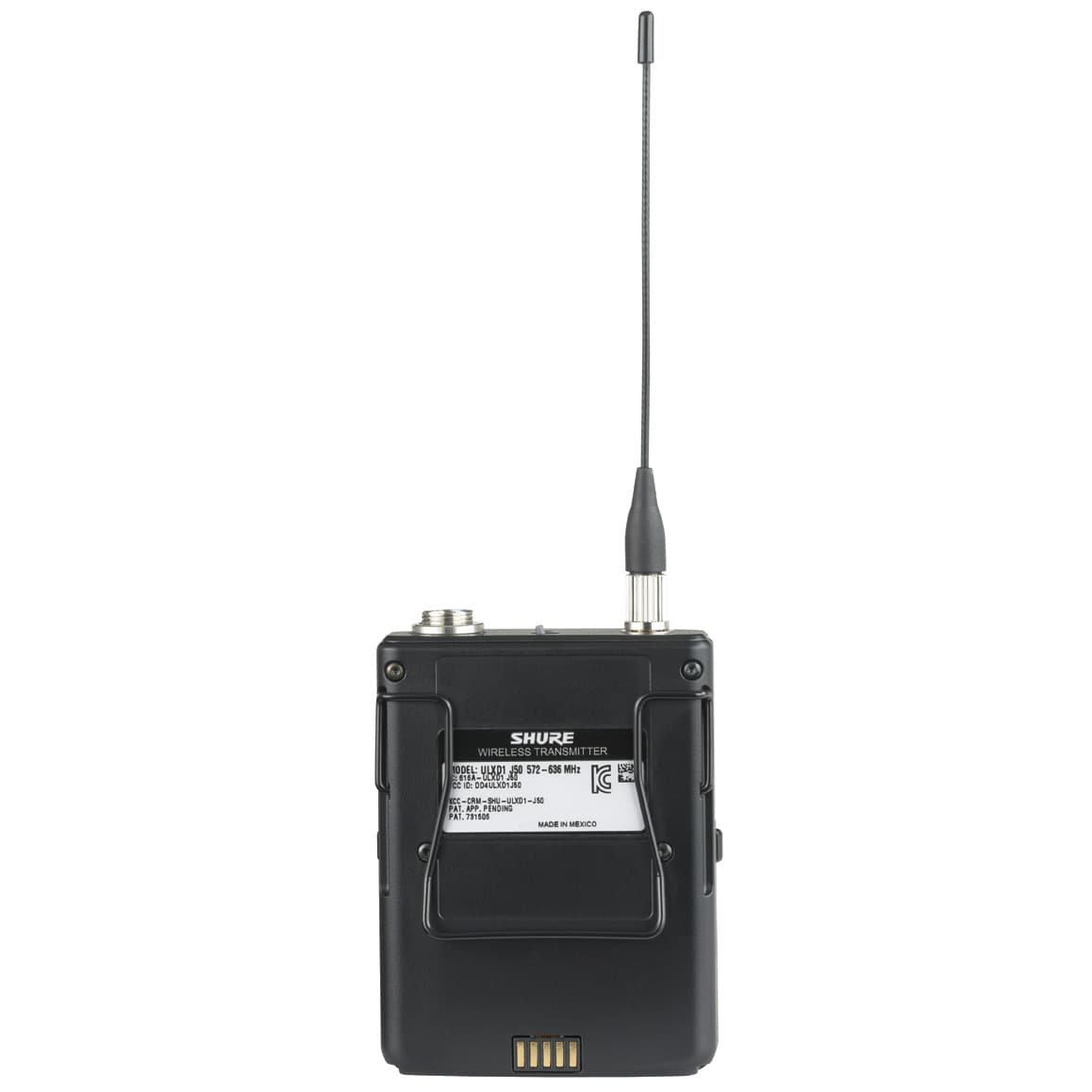
Click to zoom
Application Details
- Equipment Class
- DTS - Digital Transmission System
- Date of Grant
- Dec 30, 2014
- Application Purpose
- Original Equipment
- Date of Application
- Dec 17, 2014
- Equipment Note
- Wireless Microphone Transmitter
- Frequency Range
- 902.40000000 - 927.60000000
- Company
- Shure Incorporated
- Country
- United States
Documents & Files
Document Text
Text extracted from the exhibit documents filed with the FCC. Open a document above to read the original.
Users Manual
©2014 Shure Incorporated 27A 27230 (Rev. 1) ULX-D Digital Wireless Microphone System WIRELESS SYSTEM ULX-D USER GUIDE Sistem Mikrofon Nirkabel Digital ULX-D ULX-D 数字式无线话筒系统 ULX-D 디지털 무선 마이크 시스템 ULX-Dデジタルワイヤレスマイクロホンシステム Цифровая беспроводная микрофонная система ULX-D Sistema radiomicrofonico digitale ULX-D Sistema de micrófonos inalámbricos digitales ULX-D Digitales drahtloses Mikrofonsystem ULX-D Système de microphone sans fil numérique ULX-D ULX-D 數位式無線話筒系統 ULX-D Digital Wireless-systemen Sistema de Microfone Sem Fio Digital ULX-D ULX-D Digital Wireless-systemen IMPORTANT SAFETY INSTRUCTIONS 1. READ these instructions. 2. KEEP these instructions. 3. HEED all warnings. 4. FOLLOW all instructions. 5. DO NOT use this apparatus near water. 6. CLEAN ONLY with dry cloth. 7. DO NOT block any ventilation openings. Allow sufficient distances for adequate ventila- tion and install in accordance with the manufacturer’s instructions. 8. DO NOT install near any heat sources such as open flames, radiators, heat registers, stoves, or other apparatus (including amplifiers) that produce heat. Do not place any open flame sources on the product. 9. DO NOT defeat the safety purpose of the polarized or groundingtype plug. A polarized plug has two blades with one wider than the other. A grounding type plug has two blades and a third grounding prong. The wider blade or the third prong are provided for your safety. If the provided plug does not fit into your outlet, consult an electrician for replace- ment of the obsolete outlet. 10. PROTECT the power cord from being walked on or pinched, particularly at plugs, conve- nience receptacles, and the point where they exit from the apparatus. 11. ONLY USE attachments/accessories specified by the manufacturer. 12. USE only with a cart, stand, tripod, bracket, or table specified by the manu- facturer, or sold with the apparatus. When a cart is used, use caution when moving the cart/apparatus combination to avoid injury from tip-over. 13. UNPLUG this apparatus during lightning storms or when unused for long periods of time. 14. REFER all servicing to qualified service personnel. Servicing is required when the ap- paratus has been damaged in any way, such as power supply cord or plug is damaged, liquid has been spilled or objects have fallen into the apparatus, the apparatus has been exposed to rain or moisture, does not operate normally, or has been dropped. 15. DO NOT expose the apparatus to dripping and splashing. DO NOT put objects filled with liquids, such as vases, on the apparatus. 16. The MAINS plug or an appliance coupler shall remain readily operable. 17. The airborne noise of the Apparatus does not exceed 70dB (A). 18. Apparatus with CLASS I construction shall be connected to a MAINS socket outlet with a protective earthing connection. 19. To reduce the risk of fire or electric shock, do not expose this apparatus to rain or moisture. 20. Do not attempt to modify this product. Doing so could result in personal injury and/or product failure. 21. Operate this product within its specified operating temperature range. This symbol indicates that dangerous voltage constituting a risk of electric shock is present within this unit. This symbol indicates that there are important operating and mainte- nance instructions in the literature accompanying this unit. WARNING: This product contains a chemical known to the State of California to cause cancer and birth defects or other reproductive harm. CONSIGNES DE SÉCURITÉ IMPORTANTES 1. LIRE ces consignes. 2. CONSERVER ces consignes. 3. OBSERVER tous les avertissements. 4. SUIVRE toutes les consignes. 5. NE PAS utiliser cet appareil à proximité de l'eau. 6. NETTOYER UNIQUEMENT avec un chiffon sec. 7. NE PAS obstruer les ouvertures de ventilation. Laisser des distances suffisantes pour permettre une ventilation adéquate et effectuer l'installation en respectant les instructions du fabricant. 8. NE PAS installer à proximité d'une source de chaleur telle qu'une flamme nue, un radiateur, une bouche de chaleur, un poêle ou d'autres appareils (dont les amplificateurs) produisant de la chaleur. Ne placer aucune source à flamme nue sur le produit. 9. NE PAS détériorer la sécurité de la fiche polarisée ou de la fiche de terre. Une fiche polarisée comporte deux lames dont l'une est plus large que l'autre. Une fiche de terre comporte deux lames et une troisième broche de mise à la terre. La lame la plus large ou la troisième broche assure la sécurité de l'utilisateur. Si la fiche fournie ne s'adapte pas à la prise électrique, demander à un électricien de remplacer la prise hors normes. 10. PROTÉGER le cordon d'alimentation afin que personne ne marche dessus et que rien ne le pince, en particulier au niveau des fiches, des prises de courant et du point de sortie de l'appareil. 11. UTILISER UNIQUEMENT les accessoires spécifiés par le fabricant. 12. UTILISER uniquement avec un chariot, un pied, un trépied, un support ou une table spécifié par le fabricant ou vendu avec l'appareil. Si un chariot est utilisé, déplacer l'ensemble chariot-appareil avec précaution afin de ne pas le renverser, ce qui pourrait entraîner des blessures. 13. DÉBRANCHER l'appareil pendant les orages ou quand il ne sera pas utilisé pendant longtemps. 14. CONFIER toute réparation à du personnel qualifié. Des réparations sont nécessaires si l'appareil est endommagé d'une façon quelconque, par exemple : cordon ou prise d'alimentation endommagé, liquide renversé ou objet tombé à l'intérieur de l'appareil, exposition de l'appareil à la pluie ou à l'humidité, appareil qui ne marche pas normale- ment ou que l'on a fait tomber. 15. NE PAS exposer cet appareil aux égouttures et aux éclaboussements. NE PAS poser des objets contenant de l'eau, comme des vases, sur l'appareil. 16. La prise SECTEUR ou un coupleur d’appareil électrique doit rester facilement utilisable. 17. Le bruit aérien de l'appareil ne dépasse pas 70 dB (A). 18. L'appareil de construction de CLASSE I doit être…
Text truncated - open the document above for the full version.
Cover Letter(s)
November 05, 2014 Elite Electronic Engineering, Inc. 1516 Centre Circle Downers Grove, Illinois 60515-1082 SUBJECT: Request for Non-disclosure for FCC ID: DD4ULXD1X52 To Whom It May Concern: Pursuant to 47 CFR Section 0.459, Shure Incorporated hereby requests non-disclosure and confidential treatment of the following materials submitted in support of FCC certification application for FCC ID # DD4ULXD1X52: a. Schematic Diagrams b. Operational Description c. Block Diagram d. Parts List e. Tune Up Procedure Above materials contain trade secrets, proprietary and technical information which would customarily be guarded from competitors under 47 CFR section 0.457(d)(2). Disclosure or publication of any portion of this company confidential material to other parties could cause substantial competitive harm and provide unjustified benefits for competitors. Shure Incorporated understands that pursuant to 47 CFR section 0.457(d)(1)(ii) disclosure of the applicant and all accompanying documentation will not be made before the date of the grant. Sincerely yours, Craig Kozokar EMC Project Engineer, Global Compliance Shure Incorporated
RF Exposure Info
802 N. Twin Oaks Valley Road, Suite 105 • San Marcos, CA 92069 • U.S.A. TEL (760) 471-2100 • FAX (760) 471-2121 http://www.rfexposurelab.com CERTIFICATE OF COMPLIANCE SAR EVALUATION Shure Incorporated Dates of Test: September 25, 2014 5800 W. Touhy Avenue Test Report Number: SAR.20140905 Niles, IL 60714 This wireless mobile and/or portable device has been shown to be compliant for localized specific absorption rate (SAR) for uncontrolled environment/general exposure limits specified in ANSI/IEEE Std. C95.1-1992 and had been tested in accordance with the measurement procedures specified in IEEE 1528-2013 and IEC 62209-2:2010 (See test report). I attest to the accuracy of the data. All measurements were performed by myself or were made under my supervision and are correct to the best of my knowledge and belief. I assume full responsibility for the completeness of these measurements and vouch for the qualifications of all persons taking them. RF Exposure Lab, LLC certifies that no party to this application is subject to a denial of Federal benefits that includes FCC benefits pursuant to Section 5301 of the Anti-Drug Abuse Act of 1988, 21 U.S.C. 853(a). Jay M. Moulton Vice President Testing Cert. # 2387.01 FCC ID: DD4ULXD1X52 IC Certificate: 616A-ULXD1 X52 Model(s): ULXD1 X52 Test Sample: Engineering Unit Same as Production Serial No.: Eng 1 Equipment Type: Wireless Body Worn Microphone Transceiver Classification: Portable Transmitter Next to Body TX Frequency Range: 902 – 928 MHz Frequency Tolerance: ± 2.5 ppm Maximum RF Output: 915 MHz – 13.01 dB Conducted Signal Modulation: 8PSK Complex Modulation (156.25 kbps) Battery Types: Standard (AA); Li-Ion Antenna Type (Length): Delta Electronics Manuf. Corp. Application Type: Certification FCC Rule Parts: Part 2, 15 KDB Test Methodology: KDB 447498 D01 v05r02 Industry Canada: RSS-102, Safety Code 6 Maximum SAR Value: 0.35 W/kg Separation Distance: 0 mm © 2014 RF Exposure Lab, LLC This report shall not be reproduced except in full without the written approval of RF Exposure Lab, LLC. Report Number: SAR.20140905 Table of Contents 1. Introduction ........................................................................................................................ 3 SAR Definition [5] ................................................................................................................... 4 2. SAR Measurement Setup ................................................................................................... 5 Robotic System ...................................................................................................................... 5 System Hardware ................................................................................................................... 5 System Electronics ................................................................................................................. 6 Probe Measurement System .................................................................................................. 6 3. Probe and Dipole Calibration .............................................................................................14 4. Phantom & Simulating Tissue Specifications .....................................................................15 Head & Body Simulating Mixture Characterization ................................................................15 5. ANSI/IEEE C95.1 – 1999 RF Exposure Limits [2] ..............................................................16 Uncontrolled Environment .....................................................................................................16 Controlled Environment .........................................................................................................16 6. Measurement Uncertainty .................................................................................................17 7. System Validation..............................................................................................................18 Tissue Verification .................................................................................................................18 Test System Verification ........................................................................................................18 8. SAR Test Data Summary ..................................................................................................20 Procedures Used To Establish Test Signal ...........................................................................20 Device Test Condition ...........................................................................................................20 SAR Data Summary – 915 MHz Body ...................................................................................21 9. Test Equipment List ...........................................................................................................22 10. Conclusion ....................................................................................................................23 11. References ....................................................................................................................24 Appendix A – System Validation Plots and Data .......................................................................25 Appendix B – SAR Test Data Plots ...........................................................................................28 Appendix C – SAR Test Setup Photos ......................................................................................30 Appendix D – Probe Calibration Data Sheets ............................................................................34 Appendix E – Dipole Calibration Data Sheets ...........................................................................46 Appendix F – Phantom Calibration Data Sheets .......................................................................55 © 2014 RF Exposure Lab, LLC Page 2 of 56 This report shall not be r…
Text truncated - open the document above for the full version.
Test Report
Engineering Test Report No. 1402869-01 Measurement of RF Emissions from a Bodypack Transmitter , Model No. ULXD1 For Shure Incorporated 5800 West Touhy Avenue Niles, IL 60714 P.O. Number 4500275203 Date Tested September 2, 2014 through September 12, 2014 Test Personnel Mark Longinotti Test Specification FCC "Code of Federal Regulations" Title 47, Part 15, Subpart C, Section 15.247 for Digital Modulation Intentional Radiators Operating within The band 902-928MHz Industry Canada RSS-GEN Industry Canada RSS-210 Test Report By: Mark Longinotti EMC Engineer Requested By: Alex Stelmaszczyk Shure Incorporated Approved By: Raymond J. Klouda Registered Professional Engineer of Illinois - 44894 Engineering Test Report No. 1402869-01 TABLE OF CONTENTS PARAGRAPH DESCRIPTION OF CONTENTS PAGE NO. THIS REPORT SHALL NOT BE REPRODUCED, EXCEPT IN FULL, WITHOUT THE WRITTEN APPROVAL OF ELITE ELECTRONIC ENGINEERING INCORPORATED. Page 2 of 51 1. Introduction ................................................................................................................................................... 5 1.1. Scope of Tests ..................................................................................................................................... 5 1.2. Purpose ............................................................................................................................................... 5 1.3. Deviations, Additions and Exclusions .................................................................................................. 5 1.4. EMC Laboratory Identification ............................................................................................................. 5 1.5. Laboratory Conditions.......................................................................................................................... 5 2. Applicable Documents .................................................................................................................................. 5 3. EUT Setup and Operation ............................................................................................................................ 6 3.1. General Description ............................................................................................................................. 6 3.1.1. Power Input ................................................................................................................................. 6 3.1.2. Peripheral Equipment ................................................................................................................. 6 3.1.3. Signal Input/Output Leads .......................................................................................................... 6 3.1.4. Grounding ................................................................................................................................... 6 3.2. Software ............................................................................................................................................... 6 3.3. Operational Mode ................................................................................................................................ 6 3.4. EUT Modifications ................................................................................................................................ 6 4. Test Facility and Test Instrumentation ......................................................................................................... 6 4.1. Shielded Enclosure .............................................................................................................................. 6 4.2. Test Instrumentation ............................................................................................................................ 6 4.3. Calibration Traceability ........................................................................................................................ 6 4.4. Measurement Uncertainty ................................................................................................................... 7 5. Test Procedures ........................................................................................................................................... 7 5.1. Powerline Conducted Emissions ......................................................................................................... 7 5.1.1. Requirements .............................................................................................................................. 7 5.2. 6dB Bandwidth ..................................................................................................................................... 7 5.2.1. Requirement................................................................................................................................ 7 5.2.2. Procedures .................................................................................................................................. 7 5.2.3. Results ........................................................................................................................................ 7 5.3. Peak Conducted Output Power ........................................................................................................... 8 5.3.1. Requirements .............................................................................................................................. 8 5.3.2. Procedures .................................................................................................................................. 8 5.3.3. Results ........................................................................................................................................ 8 5.4. Effective Isotropic Radiated Power (EIRP) .......................................................................................... 8 5.4.1. Requirements .................................................…
Text truncated - open the document above for the full version.
Test Setup Photos
Engineering Test Report No. 1402869-01 Page 15 of 51 Figure 2 Test Setup for Radiated Emissions, 30MHz to 1GHz – Horizontal Polarization Test Setup for Radiated Emissions, 30MHz to 1GHz – Vertical Polarization Engineering Test Report No. 1402869-01 Page 16 of 51 Figure 3 Test Setup for Radiated Emissions, 1GHz to 10GHz – Horizontal Polarization Test Setup for Radiated Emissions, 1GHz to 10GHz – Vertical Polarization
Contact Information
Applicant
Craig Kozokar(EMC Project Engineer)
Test Firm
Elite Electronic Engineering Inc.Kevin Halpin
Technical Specifications
| # | Rule Parts | Frequency Range | Power Output |
|---|---|---|---|
| 1 | 15C | 902.4 MHz - 927.6 MHz | 45.00 mW |
Other Applications from Shure Incorporated
DD4IMXBP
Dec 24, 2025UC Wall
Equipment Class
NII - Unlicensed National Information Infrastructure TXDD4SLXD3EG57
Jul 25, 2025Plug-on Wireless Transmitter
Equipment Class
DTS - Digital Transmission System
DD4ULXD8G50
Sep 18, 2024Wireless Gooseneck Transmitter
Equipment Class
DWM - Part 15 Wireless Microphone
DD4ULXD8H50
Sep 18, 2024Wireless Gooseneck Transmitter
Equipment Class
DWM - Part 15 Wireless Microphone
DD4ULXD6G50
Sep 08, 2024Wireless Boundary Transmitter
Equipment Class
TLD - Licensed LPAS Device