DD4ULXD2H50Wireless Microphone Transmitter
Shure Incorporated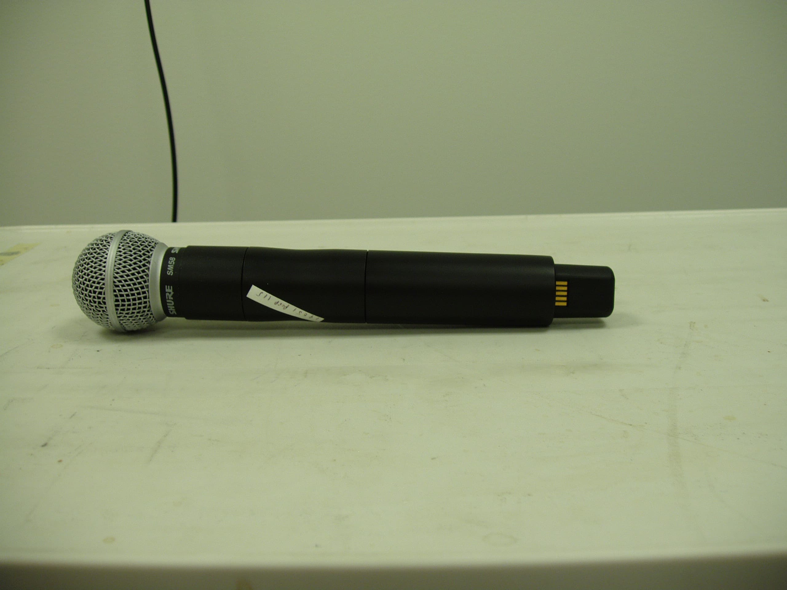
Click to zoom
Application Details
- Equipment Class
- TNF - Licensed Non-Broadcast Transmitter Held to Face
- Date of Grant
- Sep 10, 2013
- Application Purpose
- Original Equipment
- Date of Application
- Sep 10, 2013
- Equipment Note
- Wireless Microphone Transmitter
- Frequency Range
- 534.00000000 - 598.00000000
- Company
- Shure Incorporated
- Country
- United States
Documents & Files
Document Text
Text extracted from the exhibit documents filed with the FCC. Open a document above to read the original.
Users Manual
©2012 Shure Incorporated 27A20228 (Rev. 1) ULX-D ULX-D Digital Wireless Microphone System ULXD4D Dual Receiver ULXD4Q Quad Receiver 3 General Description Shure ULX-D™ Digital Wireless offers uncompromising 24-bit audio quality and RF performance, with intelligent, encryption-enabled hardware, flexible receiver options, and advanced rechargeability options for professional sound reinforcement. A breakthrough in wireless audio quality, Shure digital processing enables ULX-D to deliver the purest reproduction of source material ever available in a wireless system, with a wide selection of trusted Shure microphones to choose from. Extended 20 Hz – 20 kHz frequency range and flat response captures every detail with clarity, presence, and incredibly accurate low end and transient response. With greater than 120 dB, ULX-D delivers wide dynamic range for excellent signal-to-noise performance. Optimized for any input source, ULX-D eliminates the need for transmitter gain adjustments. ULX-D sets a new and unprecedented standard for spectral efficiency and signal stability. The intermodulation performance of ULX-D is an incredible advancement in wireless performance, enabling a dramatic increase in the number of simultaneous active transmitters on one TV channel. Rock-solid RF signal with zero audio artifacts extends over the entire range. For applications where secure wireless transmission is required, ULX-D offers Advanced Encryption Standard (AES) 256-bit encrypted signal for unbreakable privacy. For scalability and modular flexibility, ULX-D receivers come in single, dual, and even quad channel versions. The dual and quad channel receivers offer conveniences such as RF cascade, internal power supply, bodypack frequency diversity, audio output channel summing, and Dante™ digital networking for multi-channel audio over Ethernet. All receivers offer High-Density mode for applications where high channel counts are needed, greatly increasing the amount of simultaneous channels possible over one frequency band. Advanced Lithium-ion rechargeability provides extended transmitter battery life over alkaline batteries, battery life metering in hours and minutes accurate to within 15 minutes, and detailed tracking of battery health status. Generations ahead of any other available system in its class, ULX-D brings a new level of performance to professional sound reinforcement. Features Uncompromising Digital Wireless Audio • 24-bit/48 kHz digital audio that delivers incredibly clear and accurate reproduction of the source material • 20 Hz – 20 kHz frequency range with flat response • Greater than 120 dB dynamic range through the analog outputs • Built-in limiter circuitry prevents digital audio clipping from excessive signal levels. • 130 dB dynamic range (typical) using Dante™ digital networked audio • 60 dB of adjustable system gain easily accessible from the receiver front panel • No transmitter gain adjustments needed - optimized for any input source • Wide selection of trusted Shure Microphones Extremely Efficient and Reliable RF Performance • Up to 72 MHz overall tuning range (region dependent) • Up to 17 active transmitters in one 6 MHz TV channel (22 on an 8 MHz TV channel) • High Density mode enables up to 47 active transmitters in one 6 MHz TV channel (63 in one 8 MHz TV channel), with no audio quality degradation • Rock-solid signal stability with no audio artifacts over the entire 100 meter line-of-sight range using standard supplied ½ wave antennas • Selectable 1, 10, and 20 mW transmitter RF output power • Optimized scanning automatically finds, prioritizes, and selects the cleanest frequencies available Scalable, Intelligent Hardware • Single (half-rack), Dual and Quad (full-rack) receiver form factors for any size installation • AES 256-bit encryption on all channels • Ethernet networking for streamlined setup across multiple receivers • Wireless Workbench ® 6 software compatible for advanced frequency coordination, monitoring, and control • AMX/Crestron control • AXT600 Axient™ Spectrum Manager compatibility • Rugged metal housing on both transmitters and receiver • Dual and Quad receivers additionally feature: • RF cascade ports, internal power supply, and dual Ethernet ports • Dante™ digital networked audio over Ethernet • Bodypack Frequency Diversity ensures uninterrupted audio for mission-critical applications • Audio summing routes audio signal to multiple outputs Shure Advanced Power Management • Adapted from industry-leading Axient™ rechargeable technology • Lithium-Ion chemistry and intelligent Shure battery circuitry results in rechargeable batteries with zero memory effect and precision metering • Provides ULX-D transmitters with unmatched 11+ hours of performance time • Transmitters and receivers display remaining battery life in hours and minutes accurate to within 15 minutes • AA backwards compatibility Dual and Quad Receiver Models The ULXD4 receiver is available in dual channel and quad channel models. Both models share the same feature set and functionality, but differ in the number of channels available and the number of audio outputs. The descriptions and procedures in this guide are applicable to either the dual or the quad receiver. 4 power on n o 2 D X L U on ULXD1 ULXD1 sync push control ENTER EXIT SCAN RF AB OL OL gainaudio sync push control ENTER EXIT SCAN RF AB OL OL gainaudio a a b b b c 4 ULXD4 Digital Wireless Receiver sync 3 12 AASB900 b a c on ULXD2 on ULXD2 A 150 mA 45° line mic line mic line mic line mic line mic line mic line mic line mic line mic line mic line mic line mic a ULXD4Q Digital Wireless Receiver push control ENTER EXIT SCAN power RF AB OL OL gainaudio RF AB OL OL gainaudio RF AB OL OL gainaudio RF AB OL OL gainaudio RX1RX2RX3RX4 o n U L X D 2 <15 cm (6 in.) RF AB OL OL gainaudio RX1 sync 1-G: 01CH:03 TxOn 2-G: 01CH:06 TxOn 3-G: 01CH:08 TxOn 4-G: 01CH:12 TxOn Select RX TO SCAN 1 Receiver 2 Receiver 3 Receiver CHANNEL SCAN CROUP SCAN GROUP SCAN SC…
Text truncated - open the document above for the full version.
Cover Letter(s)
August 06, 2013 Elite Electronic Engineering, Inc. 1516 Centre Circle Downers Grove, Illinois 60515-1082 SUBJECT: REQUEST FOR NON-DISCLOSURE FOR FCC ID: DD4ULXD2H50 To Whom It May Concern: Pursuant to 47 CFR Section 0.459, Shure Incorporated hereby requests non-disclosure and confidential treatment of the following materials submitted in support of FCC certification application for FCC ID # DD4ULXD2H50: a. Schematic Diagrams b. Operational Description c. Parts List d. Tune Up Procedure Above materials contain trade secrets, proprietary and technical information which would customarily be guarded from competitors under 47 CFR section 0.457(d)(2). Disclosure or publication of any portion of this company confidential material to other parties could cause substantial competitive harm and provide unjustified benefits for competitors. Shure Incorporated understands that pursuant to 47 CFR section 0.457(d)(1)(ii) disclosure of the applicant and all accompanying documentation will not be made before the date of the grant. Sincerely yours, Craig Kozokar EMC Project Engineer, Global Compliance Shure Incorporated
Test Report
Engineering Test Report No. SEL-014B SHURE ELECTROMAGNETIC COMPATIBILITY LABORATORY TEST REPORT TEST REPORT TITLE: Electromagnetic Compatibility t ests for a Shure ULXD2 Handheld Microphone Trans mitter TEST ITEM DESCRIPTION: ULXD2 is a digital wireless handheld microphone transmitter intended for use in mid-tier presentation, installed, and performance markets. The system operates in the UHF TV band (470 to 932 MHz). Regionally dependent ImW, lOmW and 20mW out put power modes are available. The ULXD2 transmitter is capable of operating with AA alkaline batteries or Shure rechargeabl e battery packs. For: Shu re In corporated 5 800 W est Touhy Avenue Niles, IL 60714 Project ID Number: SEL-014 Date Tested: June 17, 2013 September 3, 2013 Test Pers onn el: Lovel l Cueto, Craig Kozokar, Alex Stelm aszczyk, Shaun Syas, Juan Castrejon Test Specif ic ation: FCC "Code of Federal Regulations" Title 47 Part 74 Industry Canada RSS-123 Industry Canada RSS-Gen TEST REPORT BY: POSITION APPROVED BY: 7h~rt.eL~ • SIG NATURE SEL-F-11 Ma in Body Test Form Page 1 of 52 Form RevIsion: 1 Engineering Test Report No. SEL-014B SEL-F-11 Main Body Test Form Page 2 of 52 Form Revision: 1 O:\Quality\Product Conformance-Lab Services\Global Compliance\Shure EMC Lab\ Controlled Documents\Forms and Templates\SEL-F-11 Main Body Test Form.docx TABLE OF CONTENTS PARAGRAPH DESCRIPTION OF CONTENTS PAGE NO. 0. Report Revision History ...................................................................................................................................... 4 1. Introduction ......................................................................................................................................................... 5 1.1. Scope of Tests ............................................................................................................................................ 5 1.2. Purpose ..................................................................................................................................................... 5 1.3. Deviation, Additions and Exclusions .......................................................................................................... 5 1.4. EMC Laboratory Identification ................................................................................................................... 5 1.5. Summary of Tests Performed .................................................................................................................... 5 2. Applicable Documents ......................................................................................................................................... 6 3. EUT Setup and Operation .................................................................................................................................... 6 3.1. General Description ................................................................................................................................... 6 3.1.1. Power Input ....................................................................................................................................... 6 3.1.2. Signal Input/Output Leads ................................................................................................................. 6 3.1.3. Grounding Considerations ................................................................................................................. 6 3.2. Operational Mode ..................................................................................................................................... 6 3.3. Test Setup .................................................................................................................................................. 7 3.3.1. Power Input ....................................................................................................................................... 7 3.3.2. Signal Input/Output Leads ................................................................................................................. 7 3.3.3. Test Frequency Range....................................................................................................................................7 3.3.4. Grounding Considerations ................................................................................................................. 7 3.4. Operational Mode ..................................................................................................................................... 7 3.4.1. Frequency and power output........................................................................................................................7 4. Test Instrumentation ........................................................................................................................................... 7 5. Test Procedures ................................................................................................................................................... 7 6. Other Test Conditions .......................................................................................................................................... 7 6.1. Test Personnel and Witnesses ................................................................................................................... 7 6.2. Disposition of the EUT ............................................................................................................................... 7 7. Results of Tests .................................................................................................................................................... 7 8. Conclusions .......................................................................................................................................................... 8 9. Certification ..............................................................................................................................…
Text truncated - open the document above for the full version.
Contact Information
Applicant
Craig Kozokar(EMC Project Engineer)
Technical Specifications
| # | Rule Parts | Frequency Range | Power Output | Emission | Tolerance |
|---|---|---|---|---|---|
| 1 | 74 | 534 MHz - 598 MHz | 20.00 mW | 165KD1E | 10.0000000000 ppm |
Other Applications from Shure Incorporated
DD4IMXBP
Dec 24, 2025UC Wall
Equipment Class
NII - Unlicensed National Information Infrastructure TXDD4SLXD3EG57
Jul 25, 2025Plug-on Wireless Transmitter
Equipment Class
DTS - Digital Transmission System
DD4ULXD8G50
Sep 18, 2024Wireless Gooseneck Transmitter
Equipment Class
DWM - Part 15 Wireless Microphone
DD4ULXD8H50
Sep 18, 2024Wireless Gooseneck Transmitter
Equipment Class
DWM - Part 15 Wireless Microphone
DD4ULXD6G50
Sep 08, 2024Wireless Boundary Transmitter
Equipment Class
TLD - Licensed LPAS Device