DD4UR3PWireless Microphone Transmitter
Shure Incorporated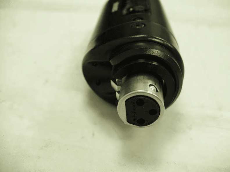
Click to zoom
Application Details
- Equipment Class
- TNF - Licensed Non-Broadcast Transmitter Held to Face
- Date of Grant
- Nov 28, 2011
- Application Purpose
- Original Equipment
- Date of Application
- Nov 28, 2011
- Equipment Note
- Wireless Microphone Transmitter
- Frequency Range
- 944.00000000 - 952.00000000
- Company
- Shure Incorporated
- Country
- United States
Documents & Files
Document Text
Text extracted from the exhibit documents filed with the FCC. Open a document above to read the original.
Users Manual
©2011 Shure Incorporated 27A16156 (Rev. 1) Printed in U.S.A. UR3 Plug-on Transmitter 3 General Description The UR3 is compatible with any wired XLR microphone and is an essential component for professional field and media production applications. It is comfortable to hold, features a back-lit display, and the audio level and power indicator LEDs are discreetly hidden. UR3 Plug-on Transmitter Features ① Joystick Enter, exit and scroll using the joystick ② XLR Connection Connects to any XLR wired microphone or device output ③ Power LED Tri-color LED, green, amber and red ④ Audio LED Tri-color LED for audio settings, red is peak ⑤ IR Window For transmitting settings from receiver to transmitter ⑥ Battery Compartment and Battery Cap Retainer Requires 2 AA batteries. Turn cover counterclockwise to open ⑦ Power Switch Press on, press and hold to turn off • UHF-R Audio Reference Companding • Wide-band tuning (region specific) • Smart, ergonomic industrial design • Selectable +12V/+48V phantom power • Sweepable high-pass filter • Programmable preset list with copy/paste to other UR3s • Selectable mic/line input • 10/50 mW RF power • Discreetly located audio and battery life indicators • IR sync ② ③④⑤ ⑥⑦ ① 4 Setup 1. Install batteries and turn power on. 2. Select the appropriate level, mic or line, to match the audio signal source: AUDIO > SENS/GAIN > SENS 3. Plug into an XLR microphone or the output of an audio device. 4. Perform a sound check: Adjust the gain until the audio LED peaks red and flickers amber: AUDIO > SENS/GAIN > GAIN Joystick Controls Use the joystick for navigating and set- ting values. Push Right (Enter) Access a menu or apply the selected value Push Left (Exit) Exit without saving changes Push Up/Down (Scroll) Scroll through menus or change a value Enter: Access a menu or save the selected value Scroll Up/Down: Scroll through menus or change a value SHURE 606.125MHz MIC Exit: Return to previous screen Joystick 5 sens/gain phantom radio utilities HPF sens/gain mic PRESET SaVED exit entersyncscan exit enter sync scan AudioABJ779-810 MHzNavigateRF OLOL AudioABJ779-810 MHzNavigateRF ® UR4D+ Wireless Receiver with Audio Reference Companding sync Control Monitor Power sync Monitor Clip ENTER EXIT push 1 2 AudioABJRF OL ® Wireless Receiver with Audio Reference Companding sync radio audio UTILITIES radio audio UTILITIES ABJ779-810 MHzNavigate OL AudioABJ779-810 MHzNavigateRF UR4D+ Wireless Receiver with Audio Reference Companding sync Control Monitor Power sync Monitor Clip ENTER EXIT push 1 2 AudioABJRF OL ® AudioRF OL Syncing with a UHF-R Receiver Align IR windows with a UHF-R receiver and press sync on the receiver. The transmitter displays SYNC SUCCESS. radio audio UTILITIES radio audio UTILITIES 6 Audio Settings AUDIO Menu SENS/GAIN > SENS Adjusts input level to match audio signal source. MIC: For microphones or mic- level outputs LINE: For line-level outputs. SENS/GAIN > GAIN Adjusts audio output to the receiver incrementally from −10 db to +20 db. PHANTOM Adds phantom power for condenser microphones. Select 12V or 48V as required for the microphone. HPF (ROLLOFF) High-pass filter. Scroll up to turn on the filter and set the low-frequency rolloff in Hz. (Scroll all the way down to turn off.) RF Settings Use the RADIO menu to adjust the following RF settings: RADIO Menu SET FREQ Adjusts group, channel or frequency. RF PWR LVL Selects 10 mW or 50 mW power level DISABLE RF Disables RF transmission. RF OFF appears on home screen. ENABLE RF (if disabled) Enables RF transmission 7 Locking and Unlocking the Transmitter To lock the transmitter, select UTILITIES > LOCK. To unlock the transmitter: 1. From the home screen, hold the joystick to the right for 5 seconds or until UN- LOCK? appears. 2. Push right again. An on-screen key appears showing the joystick sequence to unlock the transmit- ter. 3. Follow the pattern to unlock the transmitter (up, down, left, right). Utility Menu UTILITIES Menu LOCK Locks the transmitter to prevent changes to settings. MIC PRESET Acesses the preset list. DISPLAY Changes the home screen display format. BATTERY Sets battery type for more accurate battery life metering. CONTRAST Adjusts display contrast (press up/down). RESTORE Restores the factory default settings. SHURE 606.125MHz MIC 8 Preset Submenu Use the preset submenu to add, modify, or delete presets, or to clear the preset list. The submenu is not available until the first preset has been entered. Note: The UR3 is shipped with an empty preset list. 1. Access the preset list: UTILITIES > MIC PRESET 2. Scroll down to select a preset. 3. Push right to access the menu for the selected preset. SELECT Activates the selected preset. MODIFY Modify the selected preset. ADD Add a new preset after the selected preset. DELETE Deletes the selected preset. DELETEALL Deletes all presets. COPY/PASTE Copy and paste the entire preset list to another UR3. Microphone Preset The transmitter holds up to 10 microphone presets. To change or modify the presets, you must enter the microphone preset submenu: UTILITIES > MIC PRESET. From the sub-menu you can select, modify, add or delete and copy/paste settings. Accessing Presets Adding a preset: UTILITIES > MIC PRESET>ADD Use EXIT and ENTER to scroll between parameters. Use UP/DOWN to change parameter values. Note: ENTER through all parameter to save values. 9 Copy and Paste Preset List 1. On the destination UR3: select UTILITIES > MIC PRESET Highlight MIC PRESET. 2. From the source UR3: select UTILITIES > MIC PRESET > COPY/PASTE. 3. Align the IR windows and press enter on the source UR3. SUCCESS appears on the LCD of the destination UR3. Modify Microphone Presets Choose a preset from the preset list, enter the submenu, and choose MODIFY. Use the joystick to edit values: Right: move to the next value. Down: edit the selected value. Left: exit the preset without saving changes. To exit and save: Continue to scroll right, through all fields, until PRESET SAVED appears. To ed…
Text truncated - open the document above for the full version.
Cover Letter(s)
November 7, 2011 Elite Electronic Engineering, Inc. 1516 Centre Circle Downers Grove, Illinois 60515-1082 SUBJECT: REQUEST FOR NON-DISCLOSURE FOR FCC ID: DD4UR3P To Whom It May Concern: Pursuant to 47 CFR Section 0.459, Shure Incorporated hereby requests non-disclosure and confidential treatment of the following materials submitted in support of FCC certification application for FCC ID # DD4UR3P: a. Schematic Diagrams b. Operational Description c. Block Diagram d. Parts List e. Tune Up Procedure Above materials contain trade secrets, proprietary and technical information which would customarily be guarded from competitors under 47 CFR section 0.457(d)(2). Disclosure or publication of any portion of this company confidential material to other parties could cause substantial competitive harm and provide unjustified benefits for competitors. Shure Incorporated understands that pursuant to 47 CFR section 0.457(d)(1)(ii) disclosure of the applicant and all accompanying documentation will not be made before the date of the grant. Sincerely yours, Craig Kozokar EMC Project Engineer, Global Compliance Shure Incorporated
External Photos
Shure UR3 External Photographs Shure UR3 Front View Shure UR3 Back View Shure UR3 Left Side View Shure UR3 Right Side View Shure UR3 Top View (XLR) Shure UR3 Bottom View
ID Label/Location Info
Shure UR3 Label Location Shure UR3 Back View
ID Label/Location Info
Model: UR3 X1 944-952 MHz MADE IN CHINA X1-US FCC ID: DD4UR3P CR-3027 Label, Product, UR3 UR3 65AB16121 Note: Dotted red line is die cut
Internal Photos
Shure UR3 Internal Photographs UR3 PCB Top UR3 PCB Back UR3 PCB – Audio Connector Top UR3 PCB – Audio Connector Bottom
RF Exposure Info
Maximum Permissible Exposure calculations The MPE distance will be calculated for the worst case of a 100% transmitter duty cycle. For an isotropic radiator the surface area of a sphere can be used to determine the area over which the transceiver energy is radiated. Surface area of a sphere = 4 * π * radius2 In the case where there is an antenna gain, the worst case energy density is increased by the antenna gain. In this case, the exposure level for a controlled environment can be calculated as follows: MPE distance =((output power*duty cycle*10*(antenna gain/10))/(4* π*Exposure Limit [mW/cm2]))1/2 In the case of Shotgun Microphone antenna MPE distance = ((50 mW * 1 * 1.38) /( 4 * 3.14 * 1)) 1/2 = 2.9 cm
Test Report
Engineering Test Report No. 1102368-01 Rev. A Electromagnetic Compatibility Tests on a Plug-On Transmitter, Model No. UR3 For : Shure Incorporated 5800 West Touhy Avenue Niles, IL 60714 P.O. No. : 4500201046 and 4500206044 Date Received : June 2, 2011 Dates Tested : June 2, 2011 through October 14, 2011 Test Personnel : Craig M. Dinsmore, Mark E. Longinotti Specification : FCC "Code of Federal Regulations” Title 47 Part 74 Industry Canada RSS-123 Industry Canada RSS-Gen Test Report By : Mark E. Longinotti EMC Engineer Approved By : Raymond J. Klouda Registered Professional Engineer of Illinois - 44894 Elite Electronic Engineering Inc. 1516 Centre Circle Downers Grove, IL 60515 Tel : (630) 495-9770 Fax: (630) 495-9785 www.elitetest.com Engineering Test Report No. 1102368-01 Rev. A THIS REPORT SHALL NOT BE REPRODUCED, EXCEPT IN FULL, WITHOUT THE WRITTEN APPROVAL OF ELITE ELECTRONIC ENGINEERING INCORPORATED. Page 2 of 197 TABLE OF CONTENTS PARAGRAPH DESCRIPTION OF CONTENTS PAGE NO. 1. Introduction ........................................................................................................................................................ 4 1.1 Scope of Tests .......................................................................................................................................... 4 1.2 Purpose .................................................................................................................................................... 4 1.3 Deviations, Additions, and Exclusions ...................................................................................................... 4 1.4 EMC Laboratory Identification .................................................................................................................. 4 1.5 Laboratory Conditions .............................................................................................................................. 4 2. Applicable Documents ....................................................................................................................................... 4 3. EUT Setup and Operation ................................................................................................................................. 5 3.1 General Description .................................................................................................................................. 5 3.1.1 Power Input .......................................................................................................................................... 5 3.1.2 Peripheral Equipment ........................................................................................................................... 5 3.1.3 Signal Input/Output Leads .................................................................................................................... 5 3.1.4 Grounding ............................................................................................................................................. 5 The EUT was not grounded during testing........................................................................................................ 5 3.1.5 Frequency of EUT ................................................................................................................................ 5 3.2 Operational Mode ..................................................................................................................................... 5 3.3 EUT Modifications ..................................................................................................................................... 6 4. Test Facility and Test Instrumentation .............................................................................................................. 6 4.1 Shielded Enclosure ................................................................................................................................... 6 4.2 Test Instrumentation ................................................................................................................................. 6 4.3 Calibration Traceability ............................................................................................................................. 6 4.4 Measurement Uncertainty ........................................................................................................................ 6 5. Test Procedures ................................................................................................................................................ 6 5.1 RF POWER OUTPUT MEASUREMENTS ............................................................................................... 6 5.1.1 Requirements ....................................................................................................................................... 6 5.1.2 Procedures ........................................................................................................................................... 7 5.1.3 Results .................................................................................................................................................. 7 5.2 MODULATION CHARACTERISTICS ....................................................................................................... 7 5.2.1 Requirements ....................................................................................................................................... 7 5.2.2 Procedures ........................................................................................................................................... 7 5.2.3 Results .................................................................................................................................................. 7 5.3 FREQUENCY STABILITY ........................................................................................................................ 7 5.3.1 Requirements ........…
Text truncated - open the document above for the full version.
Contact Information
Applicant
Craig Kozokar(EMC Project Engineer)
Technical Specifications
| # | Rule Parts | Frequency Range | Power Output | Emission | Tolerance |
|---|---|---|---|---|---|
| 1 | 74 | 944 MHz - 952 MHz | 50.00 mW | 123KF3E | 2.5000000000 ppm |
Other Applications from Shure Incorporated
DD4IMXBP
Dec 24, 2025UC Wall
Equipment Class
NII - Unlicensed National Information Infrastructure TXDD4SLXD3EG57
Jul 25, 2025Plug-on Wireless Transmitter
Equipment Class
DTS - Digital Transmission System
DD4ULXD8G50
Sep 18, 2024Wireless Gooseneck Transmitter
Equipment Class
DWM - Part 15 Wireless Microphone
DD4ULXD8H50
Sep 18, 2024Wireless Gooseneck Transmitter
Equipment Class
DWM - Part 15 Wireless Microphone
DD4ULXD6G50
Sep 08, 2024Wireless Boundary Transmitter
Equipment Class
TLD - Licensed LPAS Device